relay RENAULT SCENIC 2011 J95 / 3.G Engine And Peripherals EDC16C36 Workshop Manual
[x] Cancel search | Manufacturer: RENAULT, Model Year: 2011, Model line: SCENIC, Model: RENAULT SCENIC 2011 J95 / 3.GPages: 431, PDF Size: 2.03 MB
Page 11 of 431

13B-11V9 MR-372-J84-13B450$030.mif
DIESEL INJECTION
Fault finding – List and location of components13B
EDC16 C36
Program No.: 91
Vdiag No.: 44, 4C, 48,
50, 54, 58
Refrigerant pressure sensor:
This sensor is located on the coolant circuit.
Engine coolant temperature sensor:
This sensor is located on the cylinder head near the engine water chamber.
Air temperature sensor:
The air temperature sensor is located at the air circuit inlet, integrated into the air flowmeter.
Turbocharging pressure sensor solenoid valve:
This solenoid valve is located on the turbocharger.
Catalytic converter:
The catalytic converter is located downstream of the turbocharger.
Fuel temperature sensor:
This sensor is located near the injection pump and injector return.
Cruise control/speed limiter on/off switch:
This switch is located in the passenger compartment to the left of the steering wheel near the lighting dimmer.
Fan unit relay:
The relay is located on the cooling radiator.
Accelerator potentiometer:
The potentiometer is located on the accelerator pedal.
Clutch pedal switch:
The switch is located on the clutch pedal.
Heater plugs:
The heater plugs are located on the cylinder head.
The richness ratio sensor:
The richness ratio sensor is mounted in the turbo outlet.
The turbocharger cooling pump:
This pump is located next to the turbocharger.
Particle filter downstream temperature sensor:
The sensor is located after the particle filter (only on certain F9Q816 engines in Vdiag 48).
Particle filter upstream temperature sensor:
The sensor is located before the particle filter (only on engine type F9Q816).
Particle filter differential pressure sensor:
The sensor is located on the particle filter (only on engine type F9Q816).
Page 13 of 431

13B-13V9 MR-372-J84-13B450$040.mif
DIESEL INJECTION
Fault finding – Role of components13B
EDC16 C36
Program No.: 91
Vdiag No.: 44, 4C, 48,
50, 54, 58
Particle filter:
The particle filter retains the particles for destruction during regeneration, preventing these particles from being
discharged into the atmosphere (engine type F9Q816 only).
TDC sensor:
The angular position is measured using a magneto-inductive sensor triggered by the machined teeth on the engine
flywheel. This sensor gives the engine speed as well as the position of the crankshaft for injection.
Camshaft sensor:
This sensor provides a signal to perform the injection cycle.
When the piston for cylinder 1 is at top dead centre (TDC), it may be either at the end of the compression stroke or
at the end of the exhaust stroke. The camshaft sensor makes the distinction between these two states.
Electric coolant pump:
The electric water pump is activated if the coolant temperature has reached a significant temperature threshold
when the engine has stopped.
Role: to cool the turbocharger when the engine is stopped.
Refrigerant pressure sensor:
Its role is to measure the refrigerant pressure in the air conditioning circuit.
Heating elements:
The heating elements heat the engine coolant to improve user comfort (only on certain types of F9Q816 engine
in Vdiag 48).
Engine coolant temperature sensor:
The engine coolant temperature sensor informs the computer of the engine coolant temperature.
Air temperature sensor:
The air temperature sensor is fitted inside the inlet manifold and informs the computer of the temperature of the air
taken in by the engine.
Turbocharging pressure sensor solenoid valve:
This solenoid valve operates the turbocharger wastegate pneumatic circuit to lower the turbocharging pressure.
Catalytic converter:
The role of the catalytic converter is to convert pollutant gases into harmless gases.
Fan unit relay:
This relay controls the activation of the engine cooling fan assembly when a temperature threshold has been
exceeded.
Accelerator potentiometer:
The accelerator potentiometer informs the computer of the position of the accelerator pedal (engine load).
Page 35 of 431

13B-35V9 MR-372-J84-13B450$090.mif
DIESEL INJECTION
Fault finding – Fault summary table13B
EDC16 C36
Program No.: 91
Vdiag No.: 44, 4C, 48,
50, 54, 58
Management of instrument panel warning lights according to the faults notified.
FaultDTC code in
hexadecimalLevel 1 fault
warning light
(orange
SERVICE
warning light)Level 2 fault
warning light
(red STOP
warning light)No fault
warning
light litOBD
warning
light lit
DF032 Thermoplunger 1 relay
control circuit1641 - - CC.1/1.DEF -
DF033 Thermoplunger 2 relay
control circuit1642 - - CC.1/1.DEF -
DF034 Thermoplunger 3 relay
control circuit1643 - - CC.1/1.DEF -
DF038 Computer 606 1.DEF/ 3.DEF 1.DEF/2.DEF 1.DEF -
DF046 Battery voltage 560 - -1.DEF/
2.DEF/
3.DEF
DF047 Computer feed voltage 2505 - - 1.DEF -
DF051 Cruise control/speed
limiter function575 - - 1.DEF -
DF053 Rail pressure
regulation function89 3.DEF/2.DEF1.DEF/4.DEF/
3.DEF--
DF054Turbocharging
solenoid valve control circuit45CC.1/CC.0/
CO/ 1.DEF--CC.1/
CC.0/CO/
1.DEF
D F055 Turbocharging
pressure regulation circuit2263 1.DEF/2.DEF - -1.DEF/
2.DEF
DF056 Air flow sensor circuit 100CO.0/CC.1/
1.DEF--CO.0/
CC.1/
1.DEF
DF059 Misfiring on cylinder 1 301 - - 1.DEF -
Page 36 of 431

13B-36V9 MR-372-J84-13B450$090.mif
DIESEL INJECTION
Fault finding – Fault summary table13B
EDC16 C36
Program No.: 91
Vdiag No.: 44, 4C, 48,
50, 54, 58
FaultDTC code in
hexadecimalLevel 1 fault
warning light
(orange
SERVICE
warning light)Level 2 fault
warning light
(red STOP
warning light)No fault
warning
light litOBD
warning
light lit
DF060 Misfiring on cylinder 2 302 - - 1.DEF -
DF061 Misfiring on cylinder 3 303 - - 1.DEF -
DF062 Misfiring on cylinder 4 304 - - 1.DEF -
DF065 Combustion misfire 300 - - 1.DEF -
DF069 Impact detected signal 1620 - 1.DEF - -
DF086 Coolant pump relay
control circuit2600CC.1/CC.0/
CO/ 1.DEF---
DF091 Vehicle speed signal 500 - - 1.DEF -
DF098 Fuel temperature
sensor circuit180 - - CC.0/CO.1 -
DF107 Computer memory 62F 1.DEF - - 1.DEF
DF119 Camshaft sensor
signal340 1.DEF/2.DEF - - -
DF120 Engine speed sensor
signal335 - 1.DEF/2.DEF - -
DF151 Main relay circuit 685 1.DEF/2.DEF - - -
DF165 Accelerator pedal
position sensor circuit2299 - 1.DEF/2.DEF 3.DEF -
DF195 Camshaft/engine
speed sensor consistency16 - - 1.DEF -
DF196 Pedal sensor circuit
gang 1225CO.0/CC.1/
1.DEF---
DF198 Pedal sensor circuit
gang 22120CO.0/CC.1/
1.DEF---
Page 61 of 431

13B-61V9 MR-372-J84-13B450$101.mif
DIESEL INJECTION
Fault finding – Interpretation of faults13B
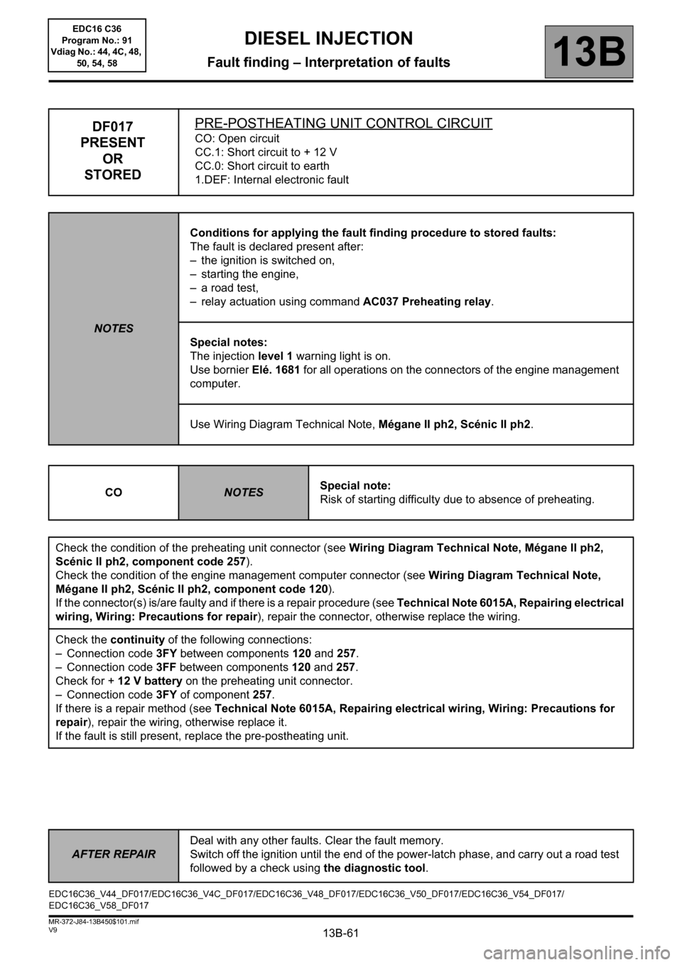
DF017
PRESENT
OR
STOREDPRE-POSTHEATING UNIT CONTROL CIRCUITCO: Open circuit
CC.1: Short circuit to + 12 V
CC.0: Short circuit to earth
1.DEF: Internal electronic fault
NOTESConditions for applying the fault finding procedure to stored faults:
The fault is declared present after:
– the ignition is switched on,
– starting the engine,
– a road test,
– relay actuation using command AC037 Preheating relay.
Special notes:
The injection level 1 warning light is on.
Use bornier Elé. 1681 for all operations on the connectors of the engine management
computer.
Use Wiring Diagram Technical Note, Mégane II ph2, Scénic II ph2.
CO
NOTESSpecial note:
Risk of starting difficulty due to absence of preheating.
Check the condition of the preheating unit connector (see Wiring Diagram Technical Note, Mégane II ph2,
Scénic II ph2, component code 257).
Check the condition of the engine management computer connector (see Wiring Diagram Technical Note,
Mégane II ph2, Scénic II ph2, component code 120).
If the connector(s) is/are faulty and if there is a repair procedure (see Technical Note 6015A, Repairing electrical
wiring, Wiring: Precautions for repair), repair the connector, otherwise replace the wiring.
Check the continuity of the following connections:
– Connection code 3FY between components 120 and 257.
– Connection code 3FF between components 120 and 257.
Check for + 12 V battery on the preheating unit connector.
– Connection code 3FY of component 257.
If there is a repair method (see Technical Note 6015A, Repairing electrical wiring, Wiring: Precautions for
repair), repair the wiring, otherwise replace it.
If the fault is still present, replace the pre-postheating unit.
EDC16C36_V44_DF017/EDC16C36_V4C_DF017/EDC16C36_V48_DF017/EDC16C36_V50_DF017/EDC16C36_V54_DF017/
EDC16C36_V58_DF017
AFTER REPAIRDeal with any other faults. Clear the fault memory.
Switch off the ignition until the end of the power-latch phase, and carry out a road test
followed by a check using the diagnostic tool.
EDC16 C36
Program No.: 91
Vdiag No.: 44, 4C, 48,
50, 54, 58
Page 63 of 431

13B-63V9 MR-372-J84-13B450$101.mif
DIESEL INJECTION
Fault finding – Interpretation of faults13B
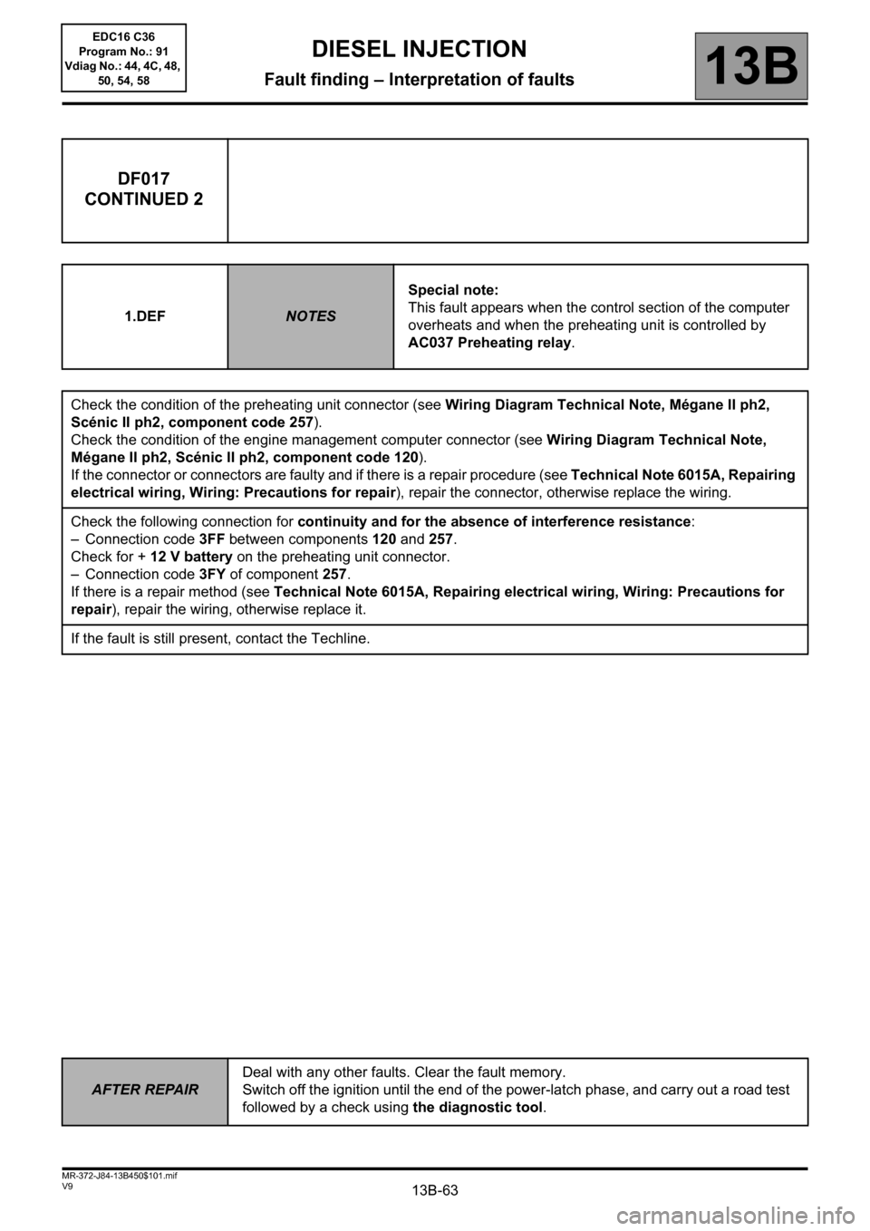
DF017
CONTINUED 2
1.DEFNOTESSpecial note:
This fault appears when the control section of the computer
overheats and when the preheating unit is controlled by
AC037 Preheating relay.
Check the condition of the preheating unit connector (see Wiring Diagram Technical Note, Mégane II ph2,
Scénic II ph2, component code 257).
Check the condition of the engine management computer connector (see Wiring Diagram Technical Note,
Mégane II ph2, Scénic II ph2, component code 120).
If the connector or connectors are faulty and if there is a repair procedure (see Technical Note 6015A, Repairing
electrical wiring, Wiring: Precautions for repair), repair the connector, otherwise replace the wiring.
Check the following connection for continuity and for the absence of interference resistance:
– Connection code 3FF between components 120 and 257.
Check for + 12 V battery on the preheating unit connector.
– Connection code 3FY of component 257.
If there is a repair method (see Technical Note 6015A, Repairing electrical wiring, Wiring: Precautions for
repair), repair the wiring, otherwise replace it.
If the fault is still present, contact the Techline.
AFTER REPAIRDeal with any other faults. Clear the fault memory.
Switch off the ignition until the end of the power-latch phase, and carry out a road test
followed by a check using the diagnostic tool.
EDC16 C36
Program No.: 91
Vdiag No.: 44, 4C, 48,
50, 54, 58
Page 64 of 431

13B-64V9 MR-372-J84-13B450$101.mif
DIESEL INJECTION
Fault finding – Interpretation of faults13B
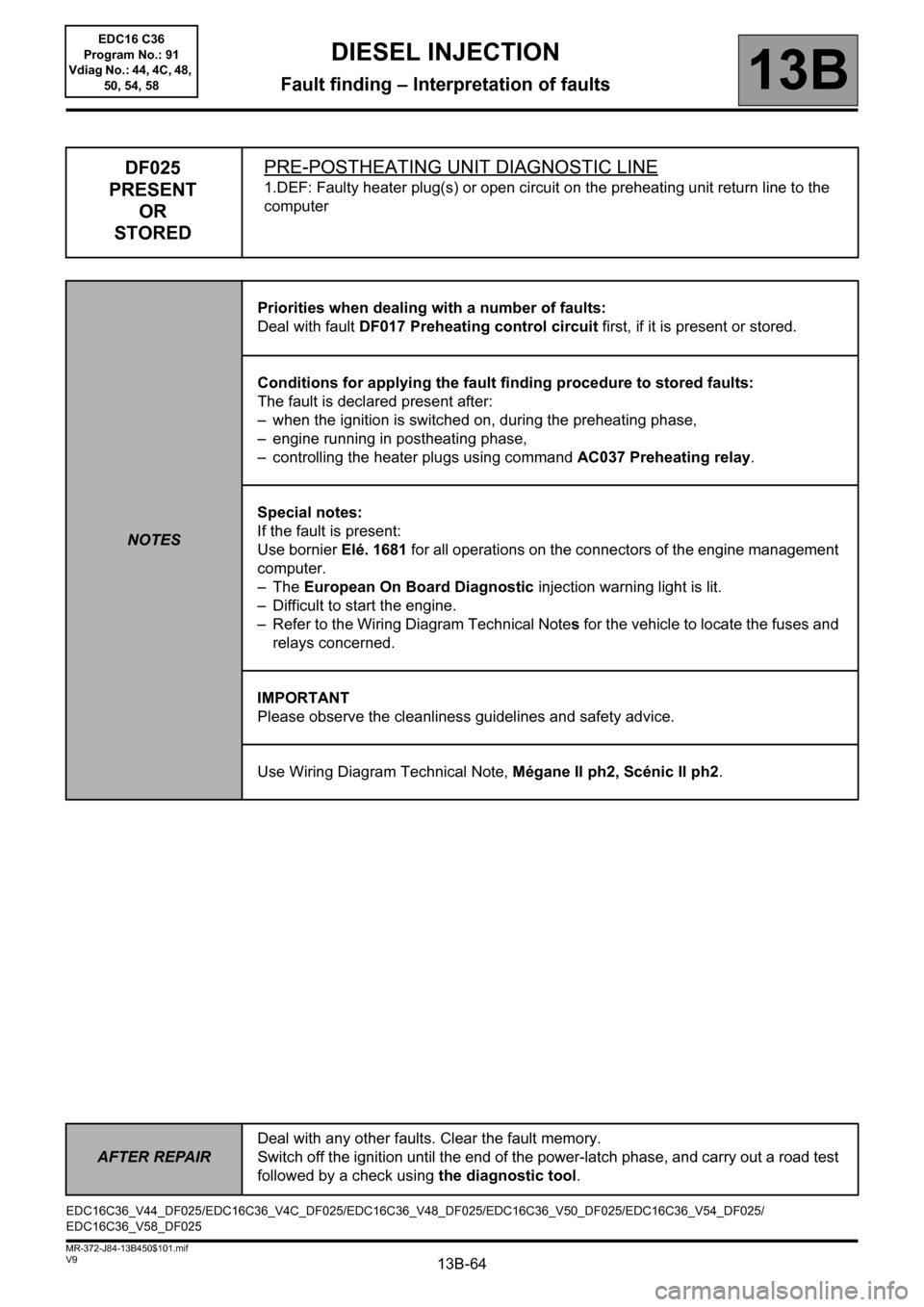
DF025
PRESENT
OR
STOREDPRE-POSTHEATING UNIT DIAGNOSTIC LINE
1.DEF: Faulty heater plug(s) or open circuit on the preheating unit return line to the
computer
NOTESPriorities when dealing with a number of faults:
Deal with fault DF017 Preheating control circuit first, if it is present or stored.
Conditions for applying the fault finding procedure to stored faults:
The fault is declared present after:
– when the ignition is switched on, during the preheating phase,
– engine running in postheating phase,
– controlling the heater plugs using command AC037 Preheating relay.
Special notes:
If the fault is present:
Use bornier Elé. 1681 for all operations on the connectors of the engine management
computer.
–The European On Board Diagnostic injection warning light is lit.
– Difficult to start the engine.
– Refer to the Wiring Diagram Technical Notes for the vehicle to locate the fuses and
relays concerned.
IMPORTANT
Please observe the cleanliness guidelines and safety advice.
Use Wiring Diagram Technical Note, Mégane II ph2, Scénic II ph2.
EDC16C36_V44_DF025/EDC16C36_V4C_DF025/EDC16C36_V48_DF025/EDC16C36_V50_DF025/EDC16C36_V54_DF025/
EDC16C36_V58_DF025
AFTER REPAIRDeal with any other faults. Clear the fault memory.
Switch off the ignition until the end of the power-latch phase, and carry out a road test
followed by a check using the diagnostic tool.
EDC16 C36
Program No.: 91
Vdiag No.: 44, 4C, 48,
50, 54, 58
Page 65 of 431

13B-65V9 MR-372-J84-13B450$101.mif
DIESEL INJECTION
Fault finding – Interpretation of faults13B
DF025
CONTINUED
Check the condition of the preheating unit connector (see Wiring Diagram Technical Note, Mégane II ph2,
Scénic II ph2, component code 257).
Check the connections on all the heater plugs.
Check the condition of the engine management computer connector (see Wiring Diagram Technical Note,
Mégane II ph2, Scénic II ph2, component code 120).
If the connector or connectors are faulty and if there is a repair procedure (see Technical Note 6015A, Repairing
electrical wiring, Wiring: Precautions for repair), repair the connector, otherwise replace the wiring.
Check the resistance of the heater plugs:
Replace any plug whose resistance is not greater than 2Ω at + 20°C.
Check the continuity of the following connections:
– Connection code 37Z between components 257 and 680.
– Connection code 37AA between components 257 and 681.
– Connection code 37AB between components 257 and 682.
– Connection code 37AC between components 257 and 683.
Check for + 12 V battery feed on the preheating unit connector (supplied by fuse FM12 70A located in the engine
relay and fuse box).
– Connection code 3FY of component 257.
If there is a repair method (see Technical Note 6015A, Repairing electrical wiring, Wiring: Precautions for
repair), repair the wiring, otherwise replace it.
– Check the engine earthing.
– Interpret command AC037 Preheating relay.
Check the condition of the engine management computer connector (see Wiring Diagram Technical Note,
Mégane II ph2, Scénic II ph2, component code 120).
If the connector(s) is/are faulty and if there is a repair procedure (see Technical Note 6015A, Repairing electrical
wiring, Wiring: Precautions for repair), repair the connector, otherwise replace the wiring.
Check the continuity, insulation and absence of interference resistance on the following connections:
– Connection code 3FY between components 120 and 257.
– Connection code 3FF between components 120 and 257.
If there is a repair method (see Technical Note 6015A, Repairing electrical wiring, Wiring: Precautions for
repair
), repair the wiring, otherwise replace it.
If the fault is still present, replace the pre-postheating unit.
AFTER REPAIRDeal with any other faults. Clear the fault memory.
Switch off the ignition until the end of the power-latch phase, and carry out a road test
followed by a check using the diagnostic tool.
EDC16 C36
Program No.: 91
Vdiag No.: 44, 4C, 48,
50, 54, 58
Page 74 of 431

13B-74V9 MR-372-J84-13B450$101.mif
DIESEL INJECTION
Fault finding – Interpretation of faults13B
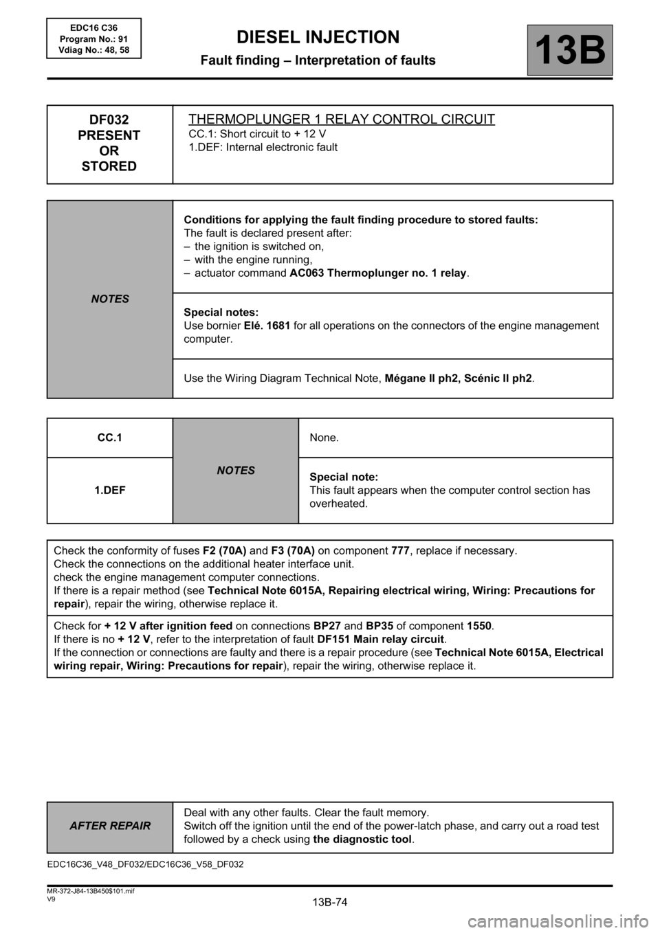
DF032
PRESENT
OR
STOREDTHERMOPLUNGER 1 RELAY CONTROL CIRCUIT
CC.1: Short circuit to + 12 V
1.DEF: Internal electronic fault
NOTESConditions for applying the fault finding procedure to stored faults:
The fault is declared present after:
– the ignition is switched on,
– with the engine running,
– actuator command AC063 Thermoplunger no. 1 relay.
Special notes:
Use bornier Elé. 1681 for all operations on the connectors of the engine management
computer.
Use the Wiring Diagram Technical Note, Mégane II ph2, Scénic II ph2.
CC.1
NOTESNone.
1.DEFSpecial note:
This fault appears when the computer control section has
overheated.
Check the conformity of fuses F2 (70A) and F3 (70A) on component 777, replace if necessary.
Check the connections on the additional heater interface unit.
check the engine management computer connections.
If there is a repair method (see Technical Note 6015A, Repairing electrical wiring, Wiring: Precautions for
repair), repair the wiring, otherwise replace it.
Check for + 12 V after ignition feed on connections BP27 and BP35 of component 1550.
If there is no + 12 V, refer to the interpretation of fault DF151 Main relay circuit.
If the connection or connections are faulty and there is a repair procedure (see Technical Note 6015A, Electrical
wiring repair, Wiring: Precautions for repair), repair the wiring, otherwise replace it.
EDC16C36_V48_DF032/EDC16C36_V58_DF032
AFTER REPAIRDeal with any other faults. Clear the fault memory.
Switch off the ignition until the end of the power-latch phase, and carry out a road test
followed by a check using the diagnostic tool.
EDC16 C36
Program No.: 91
Vdiag No.: 48, 58
Page 75 of 431

13B-75V9 MR-372-J84-13B450$101.mif
DIESEL INJECTION
Fault finding – Interpretation of faults13B
DF032
CONTINUED
Check the supply to thermoplunger 1:
– Disconnect the connector of component 898.
– Connect a test light between connection 3JB of component 898 and a chassis earth.
– Run command AC063 Thermoplunger no. 1 relay.
If the test light comes on correctly, measure the thermoplunger resistance between the connection 3JA of
component 898 and a chassis earth.
If the resistance is greater than 2Ω, replace thermoplunger 1.
If the test light does not come on, check the continuity and insulation of the following connection:
– Connection code 3JB between components 1550 and 898.
If the connection is faulty and there is a repair procedure (see Technical Note 6015A, Electrical wiring repair,
Wiring: Precautions for repair), repair the wiring, otherwise replace it.
Check the earthing on the additional heater interface unit:
– Disconnect the connector of component 1550.
– Connect a test light between connections 3JA and BP27 of component 1550.
– Run command AC063 Thermoplunger no. 1 relay.
If the test light comes on correctly, replace the additional heater interface unit.
If the test light does not come on, check the continuity and insulation from + 12 V of the following connection:
– Connection code 3JA between components 120 and 1550.
If the connection is faulty and there is a repair procedure (see Technical Note 6015A, Electrical wiring repair,
Wiring: Precautions for repair), repair the wiring, otherwise replace it.
If the fault is still present, contact the Techline.
AFTER REPAIRDeal with any other faults. Clear the fault memory.
Switch off the ignition until the end of the power-latch phase, and carry out a road test
followed by a check using the diagnostic tool.
EDC16 C36
Program No.: 91
Vdiag No.: 48, 58