ESP RENAULT SCENIC 2011 J95 / 3.G Engine And Peripherals Siemens Injection Workshop Manual
[x] Cancel search | Manufacturer: RENAULT, Model Year: 2011, Model line: SCENIC, Model: RENAULT SCENIC 2011 J95 / 3.GPages: 329, PDF Size: 1.71 MB
Page 239 of 329
13B-239
MR-372-J84-13B050$780.mif
V17
DIESEL INJECTION
Fault finding – Interpretation of parameters
Siemens Injection
SID301 and 304
Vdiag No.: 44-45-48-49-4D-4C
Program No.: B1 and B2
13B
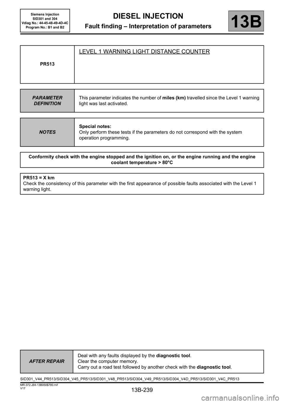
PR513
LEVEL 1 WARNING LIGHT DISTANCE COUNTER
PARAMETER
DEFINITIONThis parameter indicates the number of miles (km) travelled since the Level 1 warning
light was last activated.
NOTESSpecial notes:
Only perform these tests if the parameters do not correspond with the system
operation programming.
Conformity check with the engine stopped and the ignition on, or the engine running and the engine
coolant temperature > 80°C
PR513 = X km
Check the consistency of this parameter with the first appearance of possible faults associated with the Level 1
warning light.
AFTER REPAIRDeal with any faults displayed by the diagnostic tool.
Clear the computer memory.
Carry out a road test followed by another check with the diagnostic tool.
SID301_V44_PR513/SID304_V45_PR513/SID301_V48_PR513/SID304_V49_PR513/SID304_V4D_PR513/SID301_V4C_PR513
Page 240 of 329
13B-240
MR-372-J84-13B050$780.mif
V17
DIESEL INJECTION
Fault finding – Interpretation of parameters
Siemens Injection
SID301 and 304
Vdiag No.: 44-45-48-49-4D-4C
Program No.: B1 and B2
13B
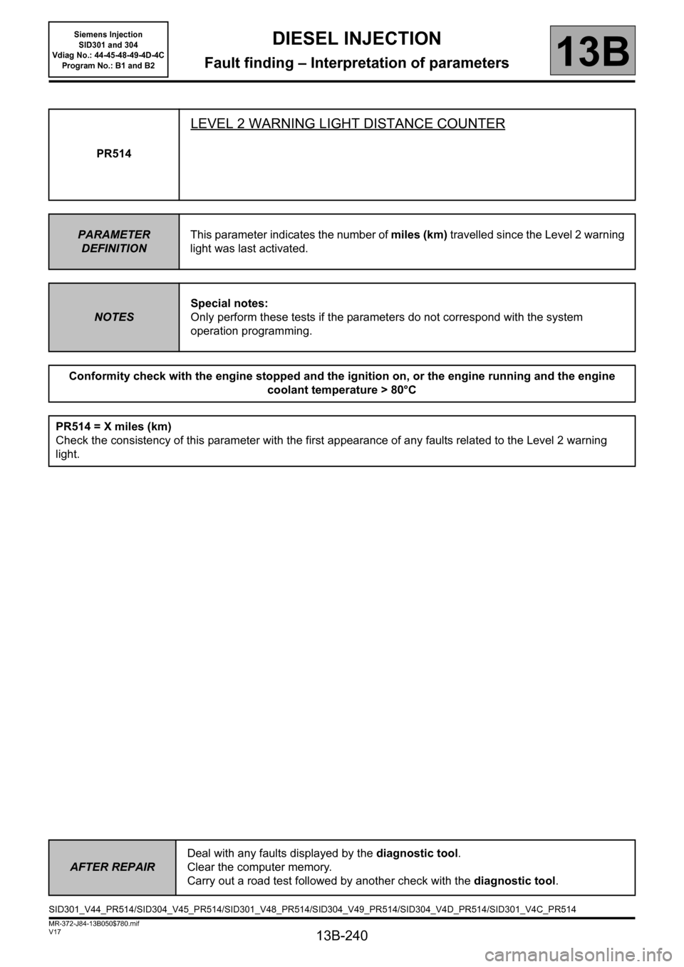
PR514
LEVEL 2 WARNING LIGHT DISTANCE COUNTER
PARAMETER
DEFINITIONThis parameter indicates the number of miles (km) travelled since the Level 2 warning
light was last activated.
NOTESSpecial notes:
Only perform these tests if the parameters do not correspond with the system
operation programming.
Conformity check with the engine stopped and the ignition on, or the engine running and the engine
coolant temperature > 80°C
PR514 = X miles (km)
Check the consistency of this parameter with the first appearance of any faults related to the Level 2 warning
light.
AFTER REPAIRDeal with any faults displayed by the diagnostic tool.
Clear the computer memory.
Carry out a road test followed by another check with the diagnostic tool.
SID301_V44_PR514/SID304_V45_PR514/SID301_V48_PR514/SID304_V49_PR514/SID304_V4D_PR514/SID301_V4C_PR514
Page 241 of 329
13B-241
MR-372-J84-13B050$780.mif
V17
DIESEL INJECTION
Fault finding – Interpretation of parameters
Siemens Injection
SID301 and 304
Vdiag No.: 44-45-48-49-4D-4C
Program No.: B1 and B2
13B
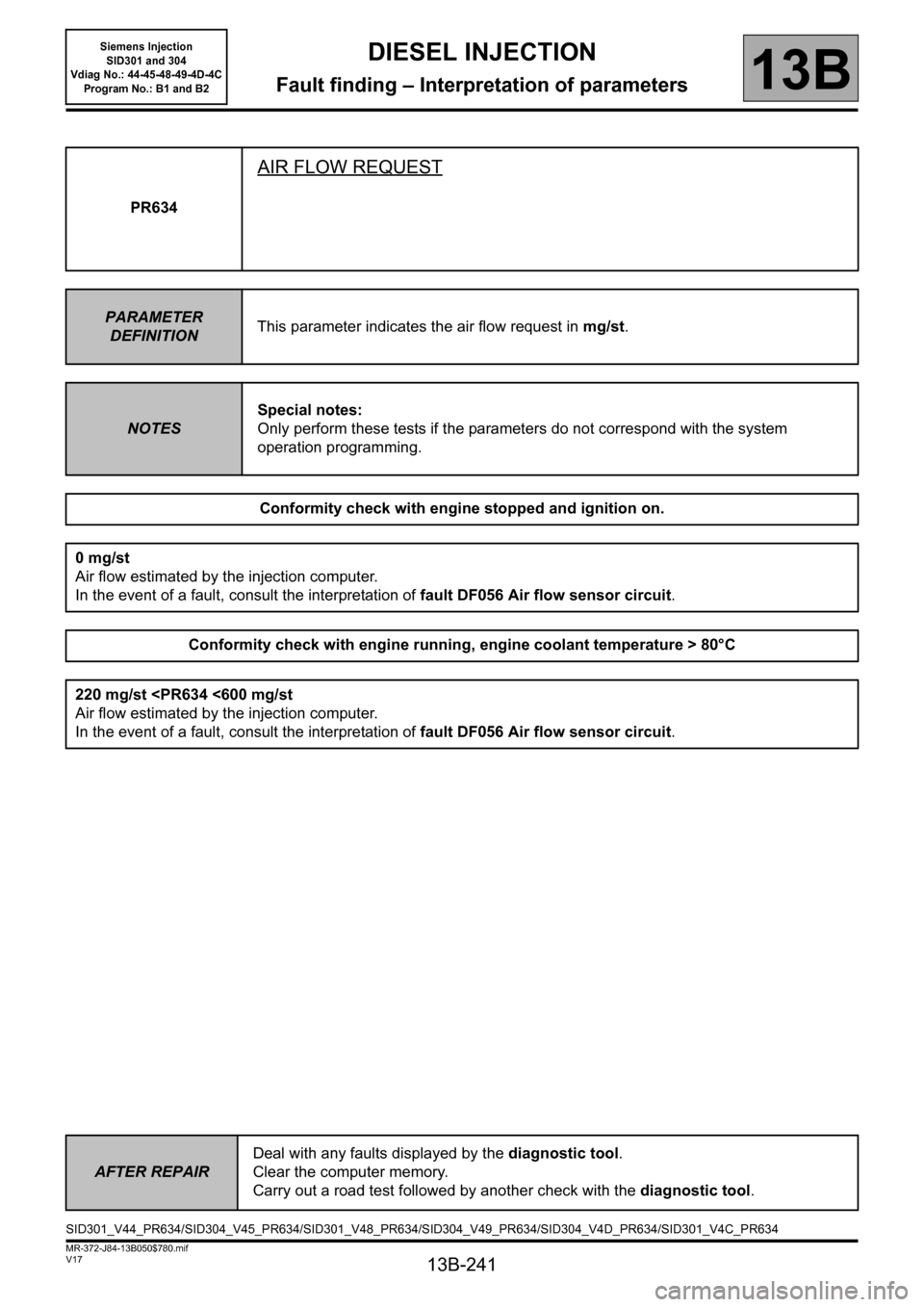
PR634
AIR FLOW REQUEST
PARAMETER
DEFINITIONThis parameter indicates the air flow request in mg/st.
NOTESSpecial notes:
Only perform these tests if the parameters do not correspond with the system
operation programming.
Conformity check with engine stopped and ignition on.
0 mg/st
Air flow estimated by the injection computer.
In the event of a fault, consult the interpretation of fault DF056 Air flow sensor circuit.
Conformity check with engine running, engine coolant temperature > 80°C
220 mg/st
In the event of a fault, consult the interpretation of fault DF056 Air flow sensor circuit.
AFTER REPAIRDeal with any faults displayed by the diagnostic tool.
Clear the computer memory.
Carry out a road test followed by another check with the diagnostic tool.
SID301_V44_PR634/SID304_V45_PR634/SID301_V48_PR634/SID304_V49_PR634/SID304_V4D_PR634/SID301_V4C_PR634
Page 242 of 329
13B-242
MR-372-J84-13B050$780.mif
V17
DIESEL INJECTION
Fault finding – Interpretation of parameters
Siemens Injection
SID301 and 304
Vdiag No.: 44-45-48-49-4D-4C
Program No.: B1 and B2
13B
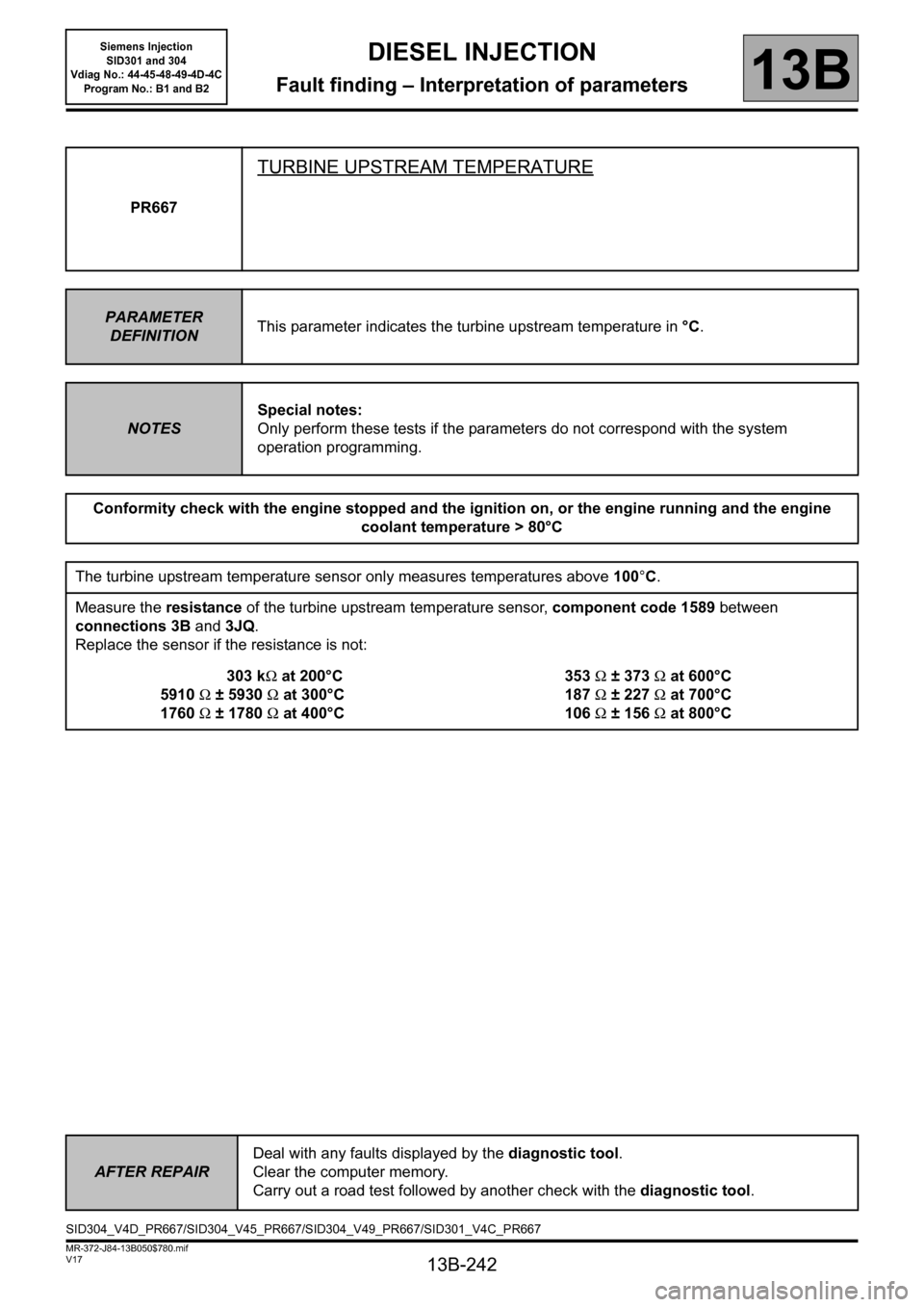
PR667
TURBINE UPSTREAM TEMPERATURE
PARAMETER
DEFINITIONThis parameter indicates the turbine upstream temperature in °C.
NOTESSpecial notes:
Only perform these tests if the parameters do not correspond with the system
operation programming.
Conformity check with the engine stopped and the ignition on, or the engine running and the engine
coolant temperature > 80°C
The turbine upstream temperature sensor only measures temperatures above 100°C.
Measure the resistance of the turbine upstream temperature sensor, component code 1589 between
connections 3B and 3JQ.
Replace the sensor if the resistance is not:
303 kΩ at 200°C
5910Ω ±5930Ω at 300°C
1760Ω ±1780Ω at 400°C353Ω ± 373Ω at 600°C
187Ω ± 227Ω at 700°C
106Ω ± 156Ω at 800°C
AFTER REPAIRDeal with any faults displayed by the diagnostic tool.
Clear the computer memory.
Carry out a road test followed by another check with the diagnostic tool.
SID304_V4D_PR667/SID304_V45_PR667/SID304_V49_PR667/SID301_V4C_PR667
Page 243 of 329
13B-243
MR-372-J84-13B050$780.mif
V17
DIESEL INJECTION
Fault finding – Interpretation of parameters
Siemens Injection
SID301 and 304
Vdiag No.: 44-45-48-49-4D-4C
Program No.: B1 and B2
13B
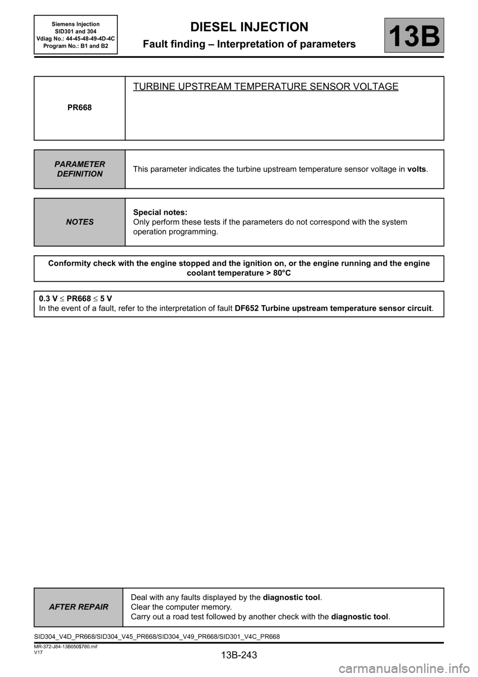
PR668
TURBINE UPSTREAM TEMPERATURE SENSOR VOLTAGE
PARAMETER
DEFINITIONThis parameter indicates the turbine upstream temperature sensor voltage in volts.
NOTESSpecial notes:
Only perform these tests if the parameters do not correspond with the system
operation programming.
Conformity check with the engine stopped and the ignition on, or the engine running and the engine
coolant temperature > 80°C
0.3 V ≤ PR668 ≤ 5 V
In the event of a fault, refer to the interpretation of fault DF652 Turbine upstream temperature sensor circuit.
AFTER REPAIRDeal with any faults displayed by the diagnostic tool.
Clear the computer memory.
Carry out a road test followed by another check with the diagnostic tool.
SID304_V4D_PR668/SID304_V45_PR668/SID304_V49_PR668/SID301_V4C_PR668
Page 244 of 329
13B-244
MR-372-J84-13B050$780.mif
V17
DIESEL INJECTION
Fault finding – Interpretation of parameters
Siemens Injection
SID301 and 304
Vdiag No.: 44-45-48-49-4D-4C
Program No.: B1 and B2
13B
*sens: sensor
*Circ: circuit
*diff: differential
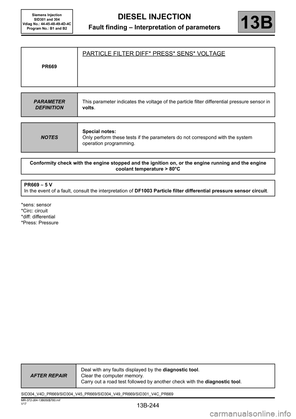
*Press: PressurePR669
PARTICLE FILTER DIFF* PRESS* SENS* VOLTAGE
PARAMETER
DEFINITIONThis parameter indicates the voltage of the particle filter differential pressure sensor in
volts.
NOTESSpecial notes:
Only perform these tests if the parameters do not correspond with the system
operation programming.
Conformity check with the engine stopped and the ignition on, or the engine running and the engine
coolant temperature > 80°C
PR669 ≈5V
In the event of a fault, consult the interpretation of DF1003 Particle filter differential pressure sensor circuit.
AFTER REPAIRDeal with any faults displayed by the diagnostic tool.
Clear the computer memory.
Carry out a road test followed by another check with the diagnostic tool.
SID304_V4D_PR669/SID304_V45_PR669/SID304_V49_PR669/SID301_V4C_PR669
Page 245 of 329
13B-245
MR-372-J84-13B050$780.mif
V17
DIESEL INJECTION
Fault finding – Interpretation of parameters
Siemens Injection
SID301 and 304
Vdiag No.: 44-45-48-49-4D-4C
Program No.: B1 and B2
13B
*temp: temperature
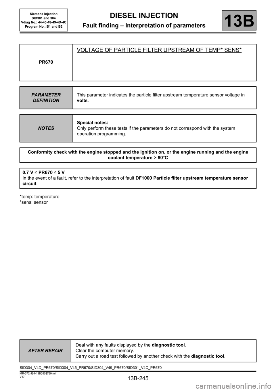
*sens: sensorPR670
VOLTAGE OF PARTICLE FILTER UPSTREAM OF TEMP* SENS*
PARAMETER
DEFINITIONThis parameter indicates the particle filter upstream temperature sensor voltage in
volts.
NOTESSpecial notes:
Only perform these tests if the parameters do not correspond with the system
operation programming.
Conformity check with the engine stopped and the ignition on, or the engine running and the engine
coolant temperature > 80°C
0.7 V ≤PR670 ≤5V
In the event of a fault, refer to the interpretation of fault DF1000 Particle filter upstream temperature sensor
circuit.
AFTER REPAIRDeal with any faults displayed by the diagnostic tool.
Clear the computer memory.
Carry out a road test followed by another check with the diagnostic tool.
SID304_V4D_PR670/SID304_V45_PR670/SID304_V49_PR670/SID301_V4C_PR670
Page 246 of 329
13B-246
MR-372-J84-13B050$780.mif
V17
DIESEL INJECTION
Fault finding – Interpretation of parameters
Siemens Injection
SID301 and 304
Vdiag No.: 44-45-48-49-4D-4C
Program No.: B1 and B2
13B
*temp: temperature
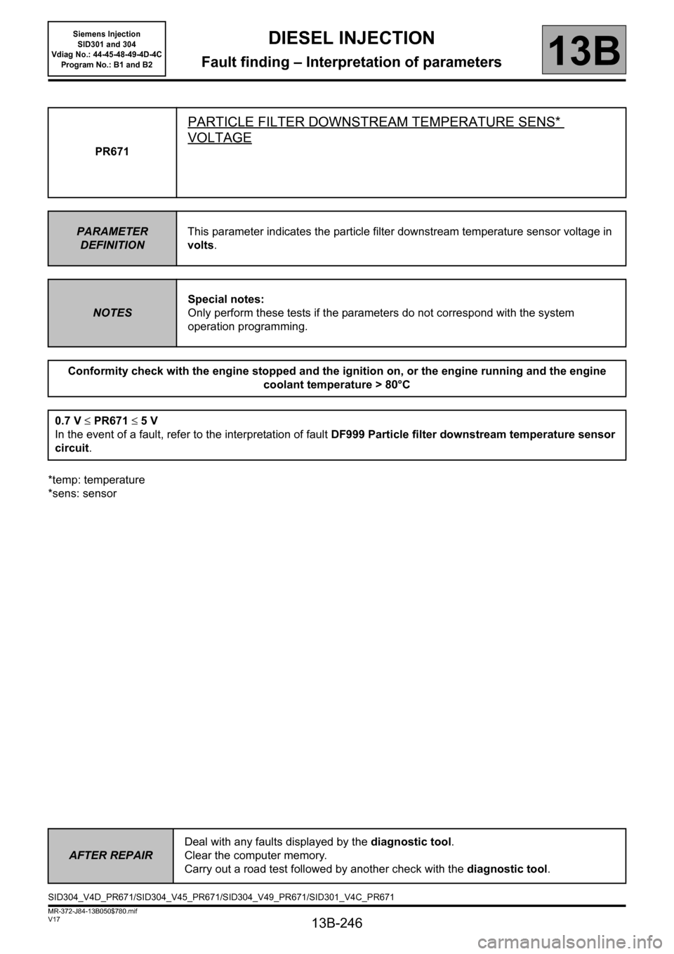
*sens: sensorPR671
PARTICLE FILTER DOWNSTREAM TEMPERATURE SENS*
VOLTAGE
PARAMETER
DEFINITIONThis parameter indicates the particle filter downstream temperature sensor voltage in
volts.
NOTESSpecial notes:
Only perform these tests if the parameters do not correspond with the system
operation programming.
Conformity check with the engine stopped and the ignition on, or the engine running and the engine
coolant temperature > 80°C
0.7 V ≤PR671 ≤5V
In the event of a fault, refer to the interpretation of fault DF999 Particle filter downstream temperature sensor
circuit.
AFTER REPAIRDeal with any faults displayed by the diagnostic tool.
Clear the computer memory.
Carry out a road test followed by another check with the diagnostic tool.
SID304_V4D_PR671/SID304_V45_PR671/SID304_V49_PR671/SID301_V4C_PR671
Page 247 of 329
13B-247
MR-372-J84-13B050$780.mif
V17
DIESEL INJECTION
Fault finding – Interpretation of parameters
Siemens Injection
SID301 and 304
Vdiag No.: 44-45-48-49-4D-4C
Program No.: B1 and B2
13B
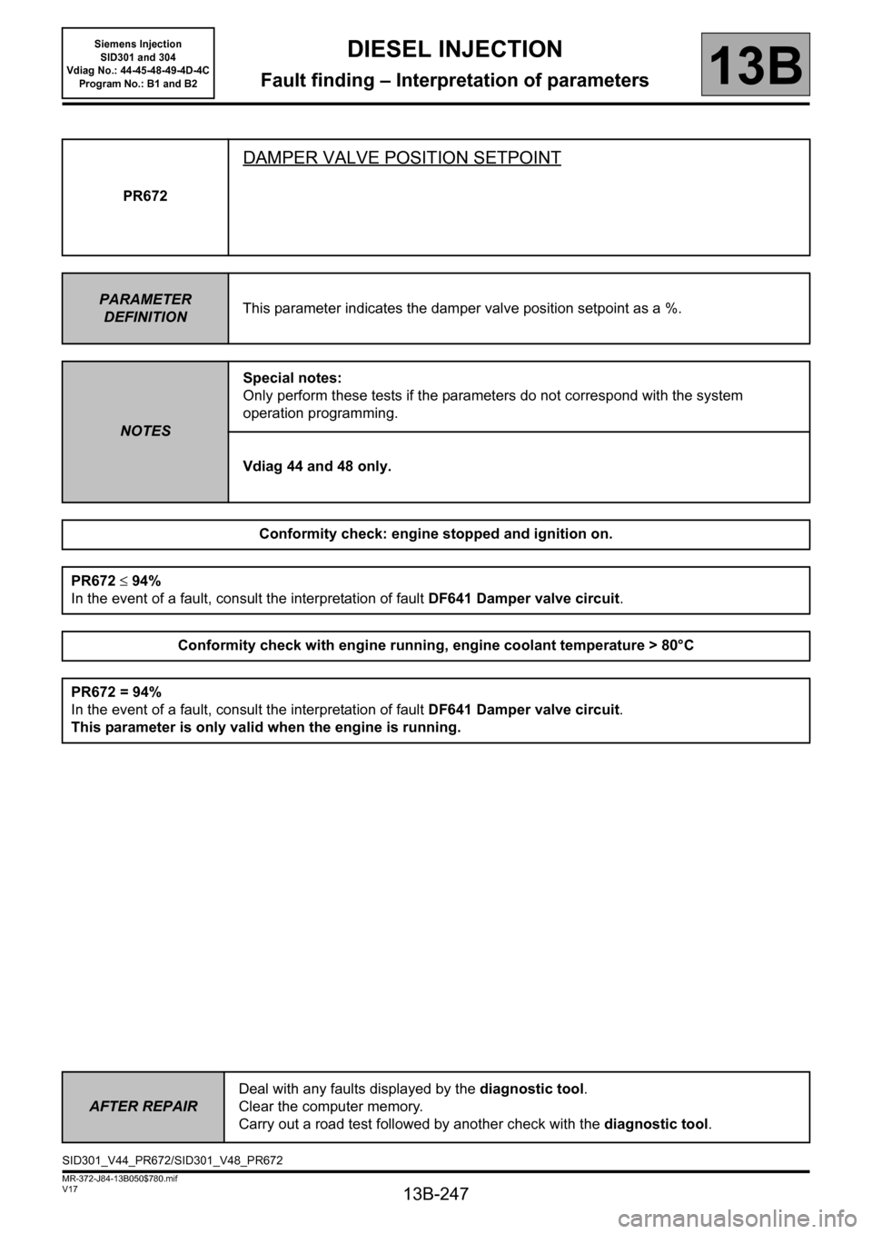
PR672
DAMPER VALVE POSITION SETPOINT
PARAMETER
DEFINITIONThis parameter indicates the damper valve position setpoint as a %.
NOTESSpecial notes:
Only perform these tests if the parameters do not correspond with the system
operation programming.
Vdiag 44 and 48 only.
Conformity check: engine stopped and ignition on.
PR672 ≤94%
In the event of a fault, consult the interpretation of fault DF641 Damper valve circuit.
Conformity check with engine running, engine coolant temperature > 80°C
PR672 = 94%
In the event of a fault, consult the interpretation of fault DF641 Damper valve circuit.
This parameter is only valid when the engine is running.
AFTER REPAIRDeal with any faults displayed by the diagnostic tool.
Clear the computer memory.
Carry out a road test followed by another check with the diagnostic tool.
SID301_V44_PR672/SID301_V48_PR672
Page 248 of 329
13B-248
MR-372-J84-13B050$780.mif
V17
DIESEL INJECTION
Fault finding – Interpretation of parameters
Siemens Injection
SID301 and 304
Vdiag No.: 44-45-48-49-4D-4C
Program No.: B1 and B2
13B
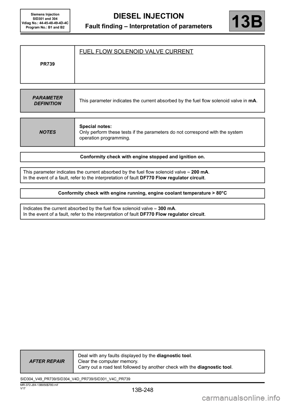
PR739
FUEL FLOW SOLENOID VALVE CURRENT
PARAMETER
DEFINITIONThis parameter indicates the current absorbed by the fuel flow solenoid valve inmA.
NOTESSpecial notes:
Only perform these tests if the parameters do not correspond with the system
operation programming.
Conformity check with engine stopped and ignition on.
This parameter indicates the current absorbed by the fuel flow solenoid valve ≈200 mA.
In the event of a fault, refer to the interpretation of fault DF770 Flow regulator circuit.
Conformity check with engine running, engine coolant temperature > 80°C
Indicates the current absorbed by the fuel flow solenoid valve ≈300 mA.
In the event of a fault, refer to the interpretation of fault DF770 Flow regulator circuit.
AFTER REPAIRDeal with any faults displayed by the diagnostic tool.
Clear the computer memory.
Carry out a road test followed by another check with the diagnostic tool.
SID304_V49_PR739/SID304_V4D_PR739/SID301_V4C_PR739