ESP RENAULT SCENIC 2011 J95 / 3.G Engine And Peripherals Siemens Injection Manual PDF
[x] Cancel search | Manufacturer: RENAULT, Model Year: 2011, Model line: SCENIC, Model: RENAULT SCENIC 2011 J95 / 3.GPages: 329, PDF Size: 1.71 MB
Page 199 of 329
13B-199
MR-372-J84-13B050$702.mif
V17
DIESEL INJECTION
Fault finding – Interpretation of parameters
Siemens Injection
SID301 and 304
Vdiag No.: 44-45-48-49-4D-4C
Program No.: B1 and B2
13B
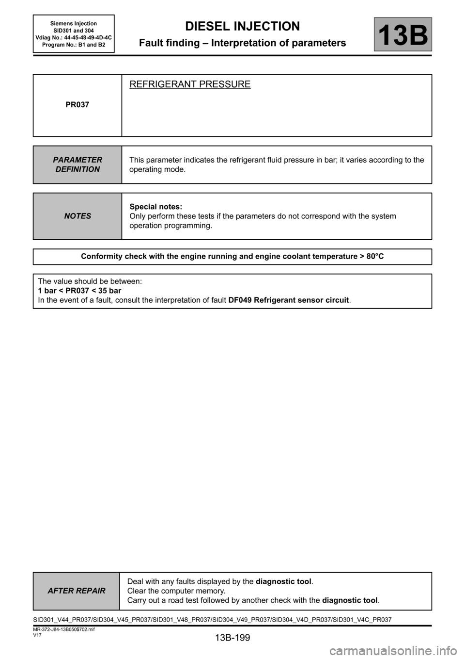
PR037
REFRIGERANT PRESSURE
PARAMETER
DEFINITIONThis parameter indicates the refrigerant fluid pressure in bar; it varies according to the
operating mode.
NOTESSpecial notes:
Only perform these tests if the parameters do not correspond with the system
operation programming.
Conformity check with the engine running and engine coolant temperature > 80°C
The value should be between:
1 bar < PR037 < 35 bar
In the event of a fault, consult the interpretation of fault DF049 Refrigerant sensor circuit.
AFTER REPAIRDeal with any faults displayed by the diagnostic tool.
Clear the computer memory.
Carry out a road test followed by another check with the diagnostic tool.
SID301_V44_PR037/SID304_V45_PR037/SID301_V48_PR037/SID304_V49_PR037/SID304_V4D_PR037/SID301_V4C_PR037
Page 201 of 329
13B-201
MR-372-J84-13B050$702.mif
V17
DIESEL INJECTION
Fault finding – Interpretation of parameters
Siemens Injection
SID301 and 304
Vdiag No.: 44-45-48-49-4D-4C
Program No.: B1 and B2
13B
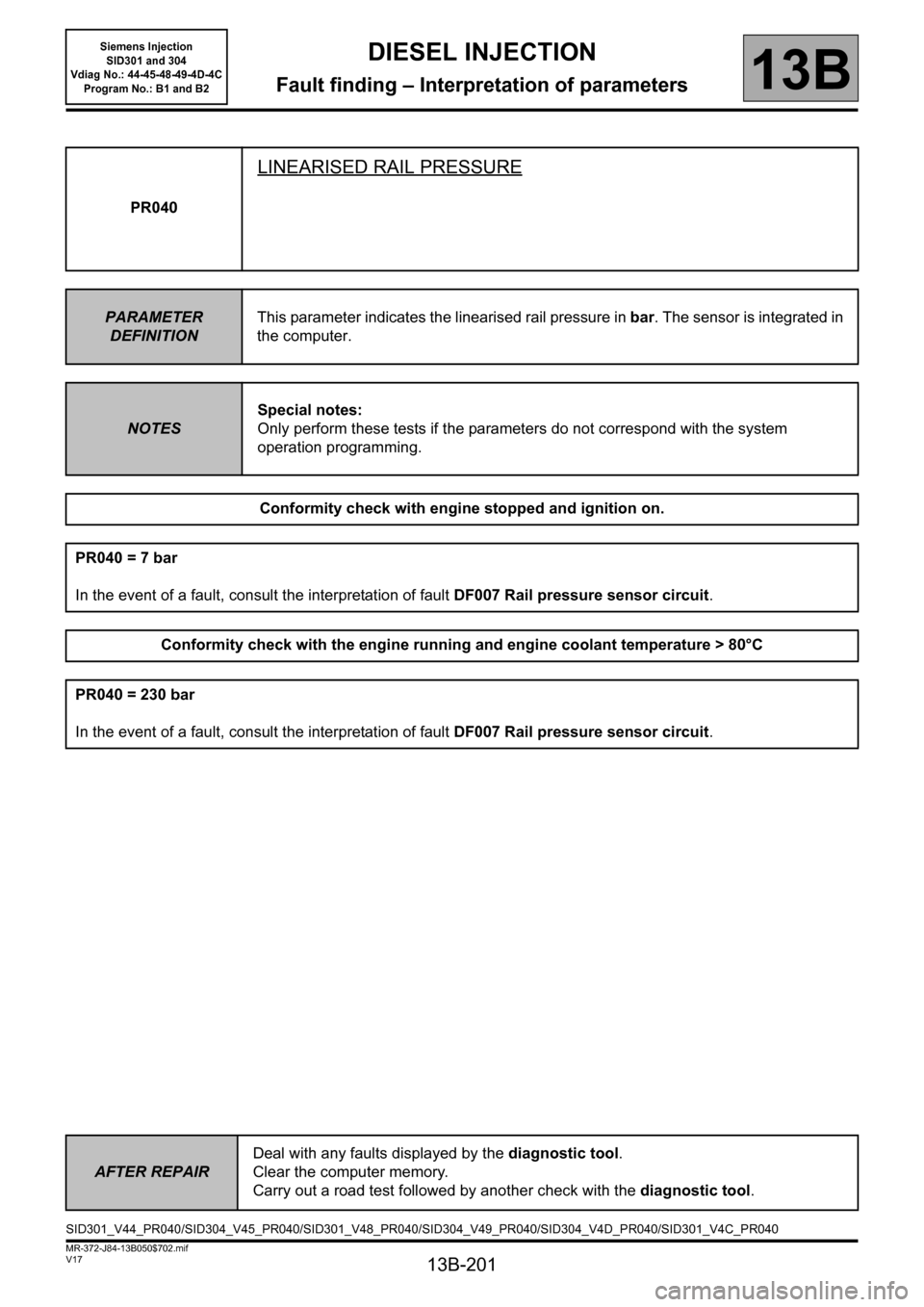
PR040
LINEARISED RAIL PRESSURE
PARAMETER
DEFINITIONThis parameter indicates the linearised rail pressure in bar. The sensor is integrated in
the computer.
NOTESSpecial notes:
Only perform these tests if the parameters do not correspond with the system
operation programming.
Conformity check with engine stopped and ignition on.
PR040 = 7 bar
In the event of a fault, consult the interpretation of fault DF007 Rail pressure sensor circuit.
Conformity check with the engine running and engine coolant temperature > 80°C
PR040 = 230 bar
In the event of a fault, consult the interpretation of fault DF007 Rail pressure sensor circuit.
AFTER REPAIRDeal with any faults displayed by the diagnostic tool.
Clear the computer memory.
Carry out a road test followed by another check with the diagnostic tool.
SID301_V44_PR040/SID304_V45_PR040/SID301_V48_PR040/SID304_V49_PR040/SID304_V4D_PR040/SID301_V4C_PR040
Page 203 of 329
13B-203
MR-372-J84-13B050$702.mif
V17
DIESEL INJECTION
Fault finding – Interpretation of parameters
Siemens Injection
SID301 and 304
Vdiag No.: 44-45-48-49-4D-4C
Program No.: B1 and B2
13B
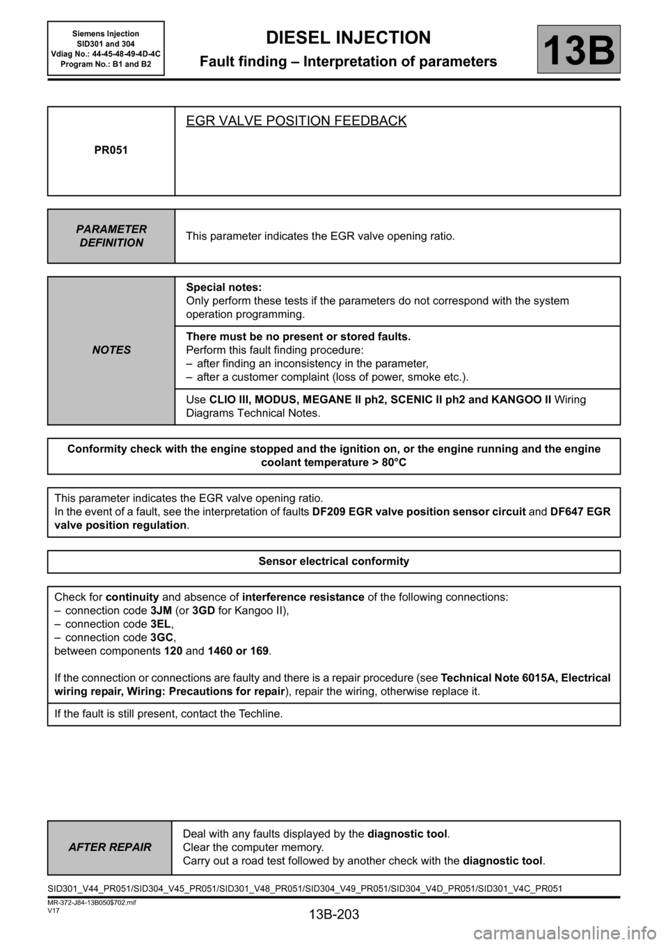
PR051
EGR VALVE POSITION FEEDBACK
PARAMETER
DEFINITIONThis parameter indicates the EGR valve opening ratio.
NOTESSpecial notes:
Only perform these tests if the parameters do not correspond with the system
operation programming.
There must be no present or stored faults.
Perform this fault finding procedure:
– after finding an inconsistency in the parameter,
– after a customer complaint (loss of power, smoke etc.).
Use CLIO III, MODUS, MEGANE II ph2, SCENIC II ph2 and KANGOO II Wiring
Diagrams Technical Notes.
Conformity check with the engine stopped and the ignition on, or the engine running and the engine
coolant temperature > 80°C
This parameter indicates the EGR valve opening ratio.
In the event of a fault, see the interpretation of faults DF209 EGR valve position sensor circuit and DF647 EGR
valve position regulation.
Sensor electrical conformity
Check for continuity and absence of interference resistance of the following connections:
– connection code 3JM (or 3GD for Kangoo II),
– connection code3EL,
– connection code3GC,
between components 120 and 1460 or 169.
If the connection or connections are faulty and there is a repair procedure (see Technical Note 6015A, Electrical
wiring repair, Wiring: Precautions for repair), repair the wiring, otherwise replace it.
If the fault is still present, contact the Techline.
AFTER REPAIRDeal with any faults displayed by the diagnostic tool.
Clear the computer memory.
Carry out a road test followed by another check with the diagnostic tool.
SID301_V44_PR051/SID304_V45_PR051/SID301_V48_PR051/SID304_V49_PR051/SID304_V4D_PR051/SID301_V4C_PR051
Page 204 of 329
13B-204
MR-372-J84-13B050$702.mif
V17
DIESEL INJECTION
Fault finding – Interpretation of parameters
Siemens Injection
SID301 and 304
Vdiag No.: 44-45-48-49-4D-4C
Program No.: B1 and B2
13B
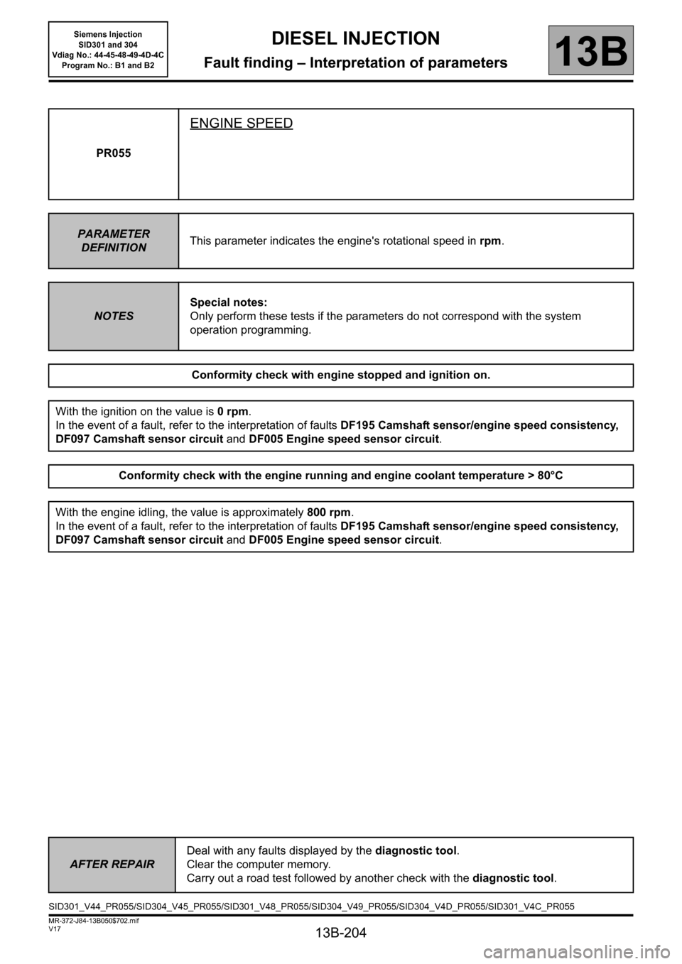
PR055
ENGINE SPEED
PARAMETER
DEFINITIONThis parameter indicates the engine's rotational speed in rpm.
NOTESSpecial notes:
Only perform these tests if the parameters do not correspond with the system
operation programming.
Conformity check with engine stopped and ignition on.
With the ignition on the value is 0 rpm.
In the event of a fault, refer to the interpretation of faults DF195 Camshaft sensor/engine speed consistency,
DF097 Camshaft sensor circuit and DF005 Engine speed sensor circuit.
Conformity check with the engine running and engine coolant temperature > 80°C
With the engine idling, the value is approximately 800 rpm.
In the event of a fault, refer to the interpretation of faults DF195 Camshaft sensor/engine speed consistency,
DF097 Camshaft sensor circuit and DF005 Engine speed sensor circuit.
AFTER REPAIRDeal with any faults displayed by the diagnostic tool.
Clear the computer memory.
Carry out a road test followed by another check with the diagnostic tool.
SID301_V44_PR055/SID304_V45_PR055/SID301_V48_PR055/SID304_V49_PR055/SID304_V4D_PR055/SID301_V4C_PR055
Page 206 of 329
13B-206
MR-372-J84-13B050$702.mif
V17
DIESEL INJECTION
Fault finding – Interpretation of parameters
Siemens Injection
SID301 and 304
Vdiag No.: 44-45-48-49-4D-4C
Program No.: B1 and B2
13B
PR063
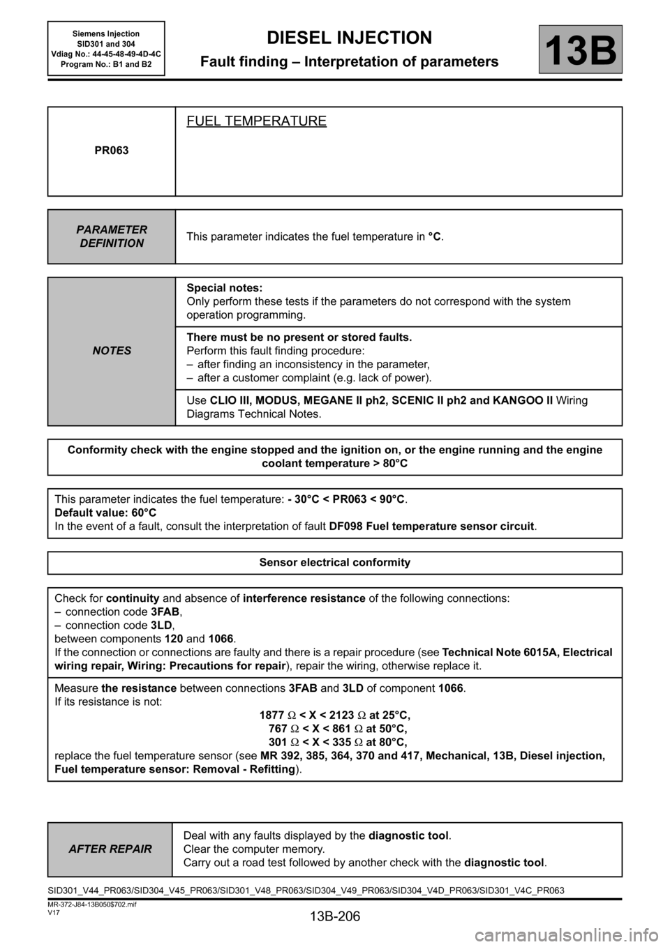
FUEL TEMPERATURE
PARAMETER
DEFINITIONThis parameter indicates the fuel temperature in °C.
NOTESSpecial notes:
Only perform these tests if the parameters do not correspond with the system
operation programming.
There must be no present or stored faults.
Perform this fault finding procedure:
– after finding an inconsistency in the parameter,
– after a customer complaint (e.g. lack of power).
Use CLIO III, MODUS, MEGANE II ph2, SCENIC II ph2 and KANGOO II Wiring
Diagrams Technical Notes.
Conformity check with the engine stopped and the ignition on, or the engine running and the engine
coolant temperature > 80°C
This parameter indicates the fuel temperature: - 30°C < PR063 < 90°C.
Default value: 60°C
In the event of a fault, consult the interpretation of fault DF098 Fuel temperature sensor circuit.
Sensor electrical conformity
Check for continuity and absence of interference resistance of the following connections:
– connection code 3FAB,
– connection code3LD,
between components 120 and 1066.
If the connection or connections are faulty and there is a repair procedure (see Technical Note 6015A, Electrical
wiring repair, Wiring: Precautions for repair), repair the wiring, otherwise replace it.
Measure the resistance between connections3FAB and 3LD of component1066.
If its resistance is not:
1877 Ω < X < 2123 Ω at 25°C,
767 Ω < X < 861 Ω at 50°C,
301 Ω < X < 335 Ω at 80°C,
replace the fuel temperature sensor (see MR 392, 385, 364, 370 and 417, Mechanical, 13B, Diesel injection,
Fuel temperature sensor: Removal - Refitting).
AFTER REPAIRDeal with any faults displayed by the diagnostic tool.
Clear the computer memory.
Carry out a road test followed by another check with the diagnostic tool.
SID301_V44_PR063/SID304_V45_PR063/SID301_V48_PR063/SID304_V49_PR063/SID304_V4D_PR063/SID301_V4C_PR063
Page 208 of 329
13B-208
MR-372-J84-13B050$702.mif
V17
DIESEL INJECTION
Fault finding – Interpretation of parameters
Siemens Injection
SID301 and 304
Vdiag No.: 44-45-48-49-4D-4C
Program No.: B1 and B2
13B
PR071
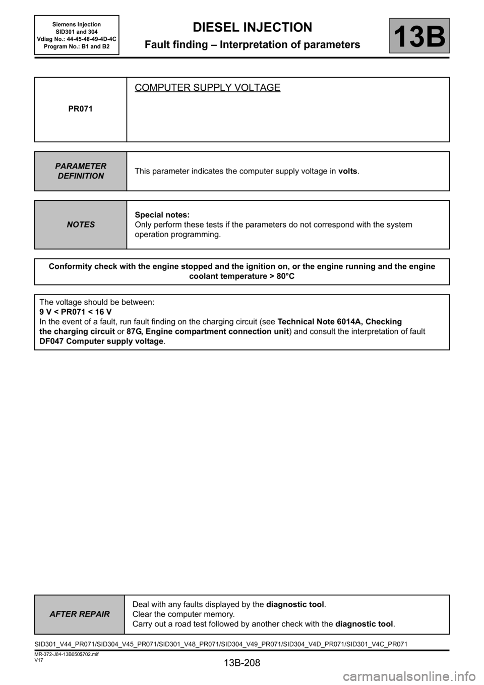
COMPUTER SUPPLY VOLTAGE
PARAMETER
DEFINITIONThis parameter indicates the computer supply voltage in volts.
NOTESSpecial notes:
Only perform these tests if the parameters do not correspond with the system
operation programming.
Conformity check with the engine stopped and the ignition on, or the engine running and the engine
coolant temperature > 80°C
The voltage should be between:
9V
the charging circuit or 87G, Engine compartment connection unit) and consult the interpretation of fault
DF047 Computer supply voltage.
AFTER REPAIRDeal with any faults displayed by the diagnostic tool.
Clear the computer memory.
Carry out a road test followed by another check with the diagnostic tool.
SID301_V44_PR071/SID304_V45_PR071/SID301_V48_PR071/SID304_V49_PR071/SID304_V4D_PR071/SID301_V4C_PR071
Page 209 of 329
13B-209
MR-372-J84-13B050$702.mif
V17
DIESEL INJECTION
Fault finding – Interpretation of parameters
Siemens Injection
SID301 and 304
Vdiag No.: 44-45-48-49-4D-4C
Program No.: B1 and B2
13B
PR076
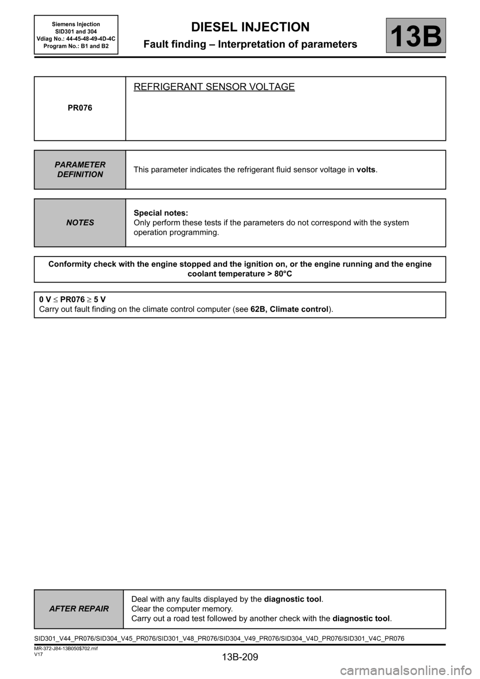
REFRIGERANT SENSOR VOLTAGE
PARAMETER
DEFINITIONThis parameter indicates the refrigerant fluid sensor voltage in volts.
NOTESSpecial notes:
Only perform these tests if the parameters do not correspond with the system
operation programming.
Conformity check with the engine stopped and the ignition on, or the engine running and the engine
coolant temperature > 80°C
0 V ≤ PR076 ≥ 5 V
Carry out fault finding on the climate control computer (see 62B, Climate control).
AFTER REPAIRDeal with any faults displayed by the diagnostic tool.
Clear the computer memory.
Carry out a road test followed by another check with the diagnostic tool.
SID301_V44_PR076/SID304_V45_PR076/SID301_V48_PR076/SID304_V49_PR076/SID304_V4D_PR076/SID301_V4C_PR076
Page 210 of 329
13B-210
MR-372-J84-13B050$702.mif
V17
DIESEL INJECTION
Fault finding – Interpretation of parameters
Siemens Injection
SID301 and 304
Vdiag No.: 44-45-48-49-4D-4C
Program No.: B1 and B2
13B
PR077
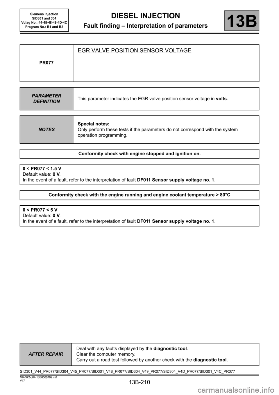
EGR VALVE POSITION SENSOR VOLTAGE
PARAMETER
DEFINITIONThis parameter indicates the EGR valve position sensor voltage in volts.
NOTESSpecial notes:
Only perform these tests if the parameters do not correspond with the system
operation programming.
Conformity check with engine stopped and ignition on.
0 < PR077 < 1.5 V
Default value: 0 V.
In the event of a fault, refer to the interpretation of fault DF011 Sensor supply voltage no. 1.
Conformity check with the engine running and engine coolant temperature > 80°C
0 < PR077 < 5 V
Default value: 0 V.
In the event of a fault, refer to the interpretation of fault DF011 Sensor supply voltage no. 1.
AFTER REPAIRDeal with any faults displayed by the diagnostic tool.
Clear the computer memory.
Carry out a road test followed by another check with the diagnostic tool.
SID301_V44_PR077/SID304_V45_PR077/SID301_V48_PR077/SID304_V49_PR077/SID304_V4D_PR077/SID301_V4C_PR077
Page 211 of 329
13B-211
MR-372-J84-13B050$702.mif
V17
DIESEL INJECTION
Fault finding – Interpretation of parameters
Siemens Injection
SID301 and 304
Vdiag No.: 44-45-48-49-4D-4C
Program No.: B1 and B2
13B
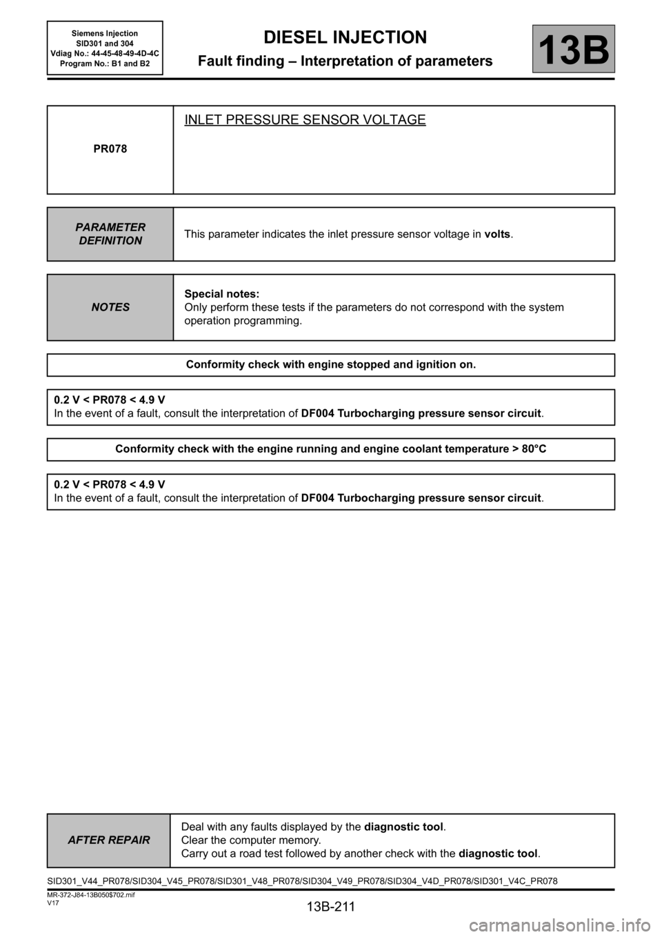
PR078
INLET PRESSURE SENSOR VOLTAGE
PARAMETER
DEFINITIONThis parameter indicates the inlet pressure sensor voltage in volts.
NOTESSpecial notes:
Only perform these tests if the parameters do not correspond with the system
operation programming.
Conformity check with engine stopped and ignition on.
0.2 V < PR078 < 4.9 V
In the event of a fault, consult the interpretation of DF004 Turbocharging pressure sensor circuit.
Conformity check with the engine running and engine coolant temperature > 80°C
0.2 V < PR078 < 4.9 V
In the event of a fault, consult the interpretation of DF004 Turbocharging pressure sensor circuit.
AFTER REPAIRDeal with any faults displayed by the diagnostic tool.
Clear the computer memory.
Carry out a road test followed by another check with the diagnostic tool.
SID301_V44_PR078/SID304_V45_PR078/SID301_V48_PR078/SID304_V49_PR078/SID304_V4D_PR078/SID301_V4C_PR078
Page 212 of 329
13B-212
MR-372-J84-13B050$702.mif
V17
DIESEL INJECTION
Fault finding – Interpretation of parameters
Siemens Injection
SID301 and 304
Vdiag No.: 44-45-48-49-4D-4C
Program No.: B1 and B2
13B
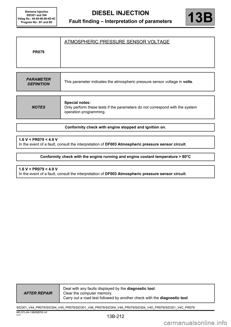
PR079
ATMOSPHERIC PRESSURE SENSOR VOLTAGE
PARAMETER
DEFINITIONThis parameter indicates the atmospheric pressure sensor voltage in volts.
NOTESSpecial notes:
Only perform these tests if the parameters do not correspond with the system
operation programming.
Conformity check with engine stopped and ignition on.
1.6 V < PR079 < 4.9 V
In the event of a fault, consult the interpretation of DF003 Atmospheric pressure sensor circuit.
Conformity check with the engine running and engine coolant temperature > 80°C
1.6 V < PR079 < 4.9 V
In the event of a fault, consult the interpretation of DF003 Atmospheric pressure sensor circuit.
AFTER REPAIRDeal with any faults displayed by the diagnostic tool.
Clear the computer memory.
Carry out a road test followed by another check with the diagnostic tool.
SID301_V44_PR079/SID304_V45_PR079/SID301_V48_PR079/SID304_V49_PR079/SID304_V4D_PR079/SID301_V4C_PR079