ESP RENAULT SCENIC 2011 J95 / 3.G Engine And Peripherals Siemens Injection Workshop Manual
[x] Cancel search | Manufacturer: RENAULT, Model Year: 2011, Model line: SCENIC, Model: RENAULT SCENIC 2011 J95 / 3.GPages: 329, PDF Size: 1.71 MB
Page 250 of 329
13B-250
MR-372-J84-13B050$780.mif
V17
DIESEL INJECTION
Fault finding – Interpretation of parameters
Siemens Injection
SID301 and 304
Vdiag No.: 44-45-48-49-4D-4C
Program No.: B1 and B2
13B
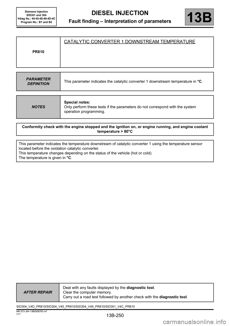
PR810
CATALYTIC CONVERTER 1 DOWNSTREAM TEMPERATURE
PARAMETER
DEFINITIONThis parameter indicates the catalytic converter 1 downstream temperature in °C.
NOTESSpecial notes:
Only perform these tests if the parameters do not correspond with the system
operation programming.
Conformity check with the engine stopped and the ignition on, or engine running, and engine coolant
temperature > 80°C
This parameter indicates the temperature downstream of catalytic converter 1 using the temperature sensor
located before the oxidation catalytic converter.
This temperature changes depending on the status of the vehicle (hot or cold).
The temperature is given in °C.
AFTER REPAIRDeal with any faults displayed by the diagnostic tool.
Clear the computer memory.
Carry out a road test followed by another check with the diagnostic tool.
SID304_V4D_PR810/SID304_V45_PR810/SID304_V49_PR810/SID301_V4C_PR810
Page 251 of 329
13B-251
MR-372-J84-13B050$780.mif
V17
DIESEL INJECTION
Fault finding – Interpretation of parameters
Siemens Injection
SID301 and 304
Vdiag No.: 44-45-48-49-4D-4C
Program No.: B1 and B2
13B
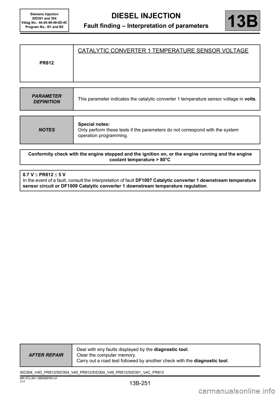
PR812
CATALYTIC CONVERTER 1 TEMPERATURE SENSOR VOLTAGE
PARAMETER
DEFINITIONThis parameter indicates the catalytic converter 1 temperature sensor voltage in volts.
NOTESSpecial notes:
Only perform these tests if the parameters do not correspond with the system
operation programming.
Conformity check with the engine stopped and the ignition on, or the engine running and the engine
coolant temperature > 80°C
0.7 V ≤PR812 ≤5V
In the event of a fault, consult the interpretation of fault DF1007 Catalytic converter 1 downstream temperature
sensor circuit or DF1009 Catalytic converter 1 downstream temperature regulation.
AFTER REPAIRDeal with any faults displayed by the diagnostic tool.
Clear the computer memory.
Carry out a road test followed by another check with the diagnostic tool.
SID304_V4D_PR812/SID304_V45_PR812/SID304_V49_PR812/SID301_V4C_PR812
Page 253 of 329
13B-253
MR-372-J84-13B050$780.mif
V17
DIESEL INJECTION
Fault finding – Interpretation of parameters
Siemens Injection
SID301 and 304
Vdiag No.: 44-45-48-49-4D-4C
Program No.: B1 and B2
13B
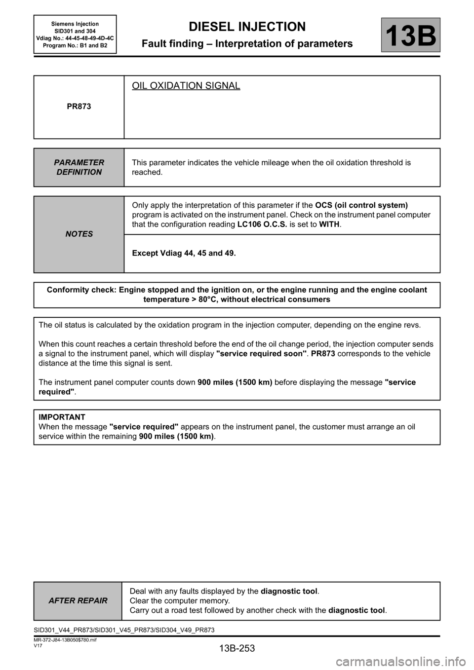
PR873
OIL OXIDATION SIGNAL
PARAMETER
DEFINITIONThis parameter indicates the vehicle mileage when the oil oxidation threshold is
reached.
NOTESOnly apply the interpretation of this parameter if the OCS (oil control system)
program is activated on the instrument panel. Check on the instrument panel computer
that the configuration reading LC106 O.C.S. is set to WITH.
Except Vdiag 44, 45 and 49.
Conformity check: Engine stopped and the ignition on, or the engine running and the engine coolant
temperature > 80°C, without electrical consumers
The oil status is calculated by the oxidation program in the injection computer, depending on the engine revs.
When this count reaches a certain threshold before the end of the oil change period, the injection computer sends
a signal to the instrument panel, which will display "service required soon". PR873 corresponds to the vehicle
distance at the time this signal is sent.
The instrument panel computer counts down 900 miles (1500 km) before displaying the message "service
required".
IMPORTANT
When the message "service required" appears on the instrument panel, the customer must arrange an oil
service within the remaining 900 miles (1500 km).
AFTER REPAIRDeal with any faults displayed by the diagnostic tool.
Clear the computer memory.
Carry out a road test followed by another check with the diagnostic tool.
SID301_V44_PR873/SID301_V45_PR873/SID304_V49_PR873
Page 255 of 329
13B-255
MR-372-J84-13B050$780.mif
V17
DIESEL INJECTION
Fault finding – Interpretation of parameters
Siemens Injection
SID301 and 304
Vdiag No.: 44-45-48-49-4D-4C
Program No.: B1 and B2
13B
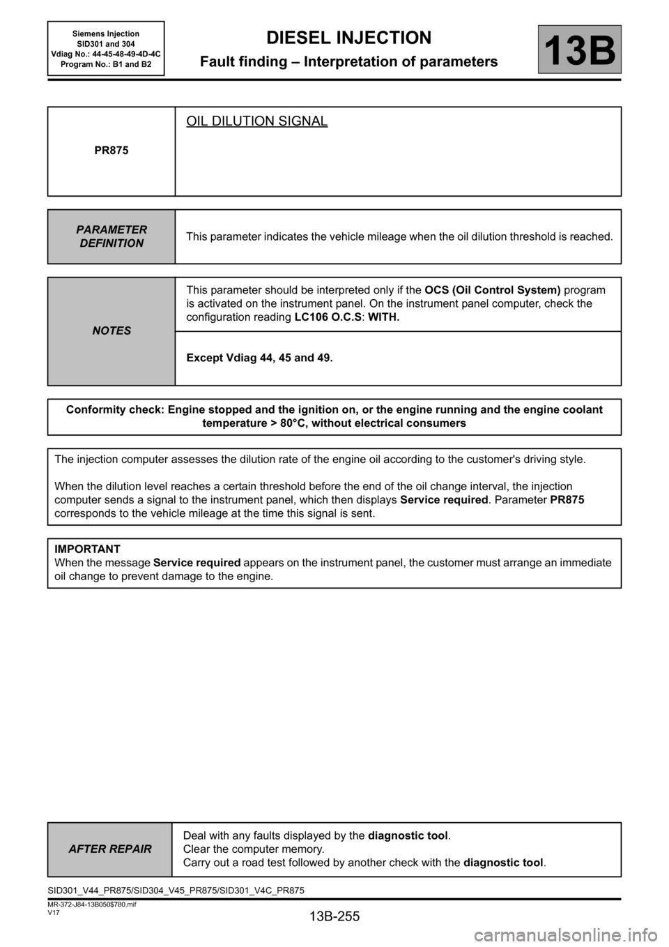
PR875
OIL DILUTION SIGNAL
PARAMETER
DEFINITIONThis parameter indicates the vehicle mileage when the oil dilution threshold is reached.
NOTESThis parameter should be interpreted only if the OCS (Oil Control System) program
is activated on the instrument panel. On the instrument panel computer, check the
configuration reading LC106 O.C.S: WITH.
Except Vdiag 44, 45 and 49.
Conformity check: Engine stopped and the ignition on, or the engine running and the engine coolant
temperature > 80°C, without electrical consumers
The injection computer assesses the dilution rate of the engine oil according to the customer's driving style.
When the dilution level reaches a certain threshold before the end of the oil change interval, the injection
computer sends a signal to the instrument panel, which then displays Service required. Parameter PR875
corresponds to the vehicle mileage at the time this signal is sent.
IMPORTANT
When the message Service required appears on the instrument panel, the customer must arrange an immediate
oil change to prevent damage to the engine.
AFTER REPAIRDeal with any faults displayed by the diagnostic tool.
Clear the computer memory.
Carry out a road test followed by another check with the diagnostic tool.
SID301_V44_PR875/SID304_V45_PR875/SID301_V4C_PR875
Page 261 of 329

13B-261
MR-372-J84-13B050$819.mif
V17
DIESEL INJECTION
Fault finding – Interpretation of commands
Siemens Injection
SID301 and 304
Vdiag No.: 44-45-48-49-4D-4C
Program No.: B1 and B2
13B
SC003
SAVE COMPUTER DATA
NOTESThis save is carried out before computer reprogramming or replacement.
On the CLIP tool, select the SC003 Save computer data.
If the following message appears:
"a saved file exists, do you want to overwrite this data?":
(this file corresponds to the last save made on the CLIP diagnostic tool)
select "YES".
Confirming this command saves the following vehicle-specific data:
– the egr valve data programming;
– options available on the vehicle and managed by the computer (e.g. air conditioning);
– data specific to injection and particle filter operation.
This information will be saved in the CLIP diagnostic tool.
When saving is finished, run command SC001 Write saved data in order to configure the new computer after
programming or reprogramming.
AFTER REPAIRDeal with any faults displayed by the diagnostic tool.
Clear the computer fault memory.
Carry out a road test followed by another check with the diagnostic tool.
SID301_V44_SC003 / SID304_V45_SC003 / SID301_V48_SC003 / SID304_V49_SC003 / SID304_V4D_SC003 / SID301_V4C_SC003
Page 262 of 329
13B-262
MR-372-J84-13B050$819.mif
V17
DIESEL INJECTION
Fault finding – Interpretation of commands
Siemens Injection
SID301 and 304
Vdiag No.: 44-45-48-49-4D-4C
Program No.: B1 and B2
13B
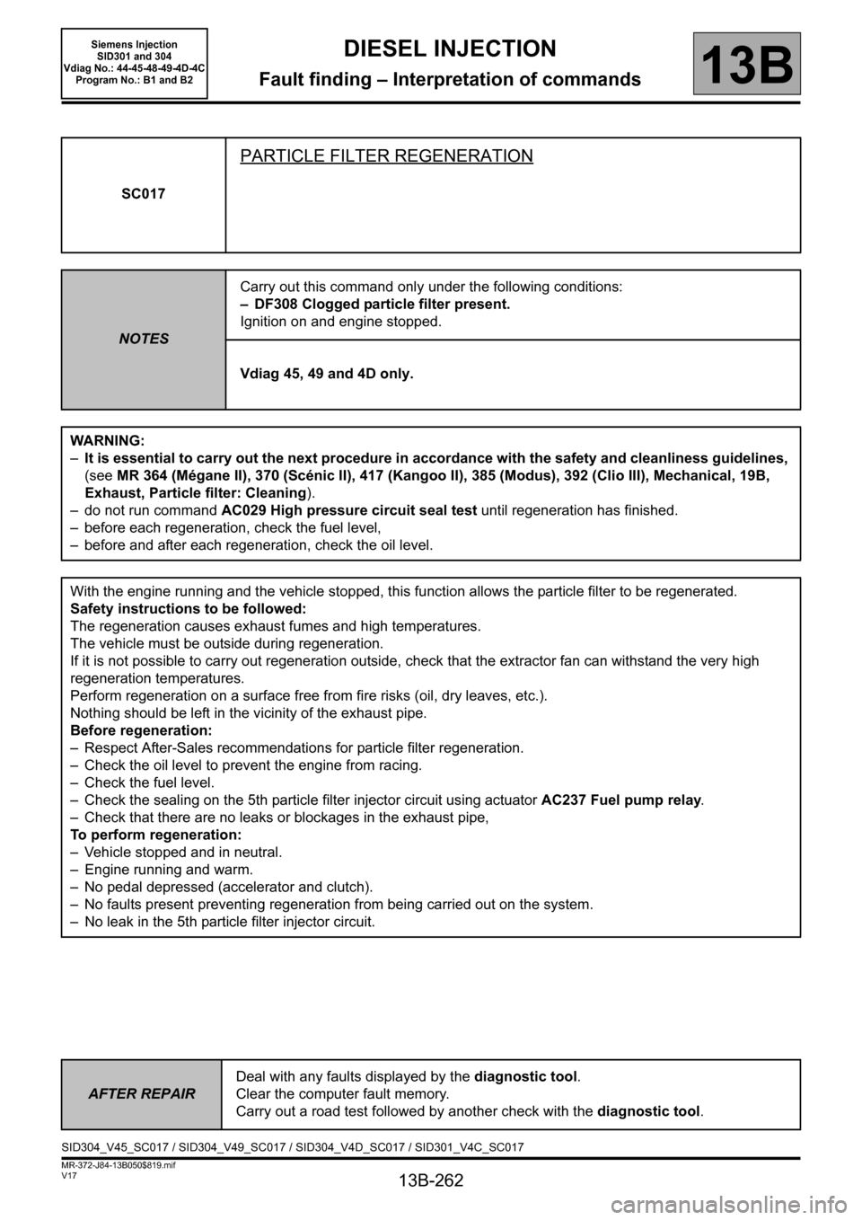
SC017
PARTICLE FILTER REGENERATION
NOTESCarry out this command only under the following conditions:
– DF308 Clogged particle filter present.
Ignition on and engine stopped.
Vdiag 45, 49 and 4D only.
WARNING:
–It is essential to carry out the next procedure in accordance with the safety and cleanliness guidelines,
(see MR 364 (Mégane II), 370 (Scénic II), 417 (Kangoo II), 385 (Modus), 392 (Clio III), Mechanical, 19B,
Exhaust, Particle filter: Cleaning).
– do not run command AC029 High pressure circuit seal test until regeneration has finished.
– before each regeneration, check the fuel level,
– before and after each regeneration, check the oil level.
With the engine running and the vehicle stopped, this function allows the particle filter to be regenerated.
Safety instructions to be followed:
The regeneration causes exhaust fumes and high temperatures.
The vehicle must be outside during regeneration.
If it is not possible to carry out regeneration outside, check that the extractor fan can withstand the very high
regeneration temperatures.
Perform regeneration on a surface free from fire risks (oil, dry leaves, etc.).
Nothing should be left in the vicinity of the exhaust pipe.
Before regeneration:
– Respect After-Sales recommendations for particle filter regeneration.
– Check the oil level to prevent the engine from racing.
– Check the fuel level.
– Check the sealing on the 5th particle filter injector circuit using actuator AC237 Fuel pump relay.
– Check that there are no leaks or blockages in the exhaust pipe,
To perform regeneration:
– Vehicle stopped and in neutral.
– Engine running and warm.
– No pedal depressed (accelerator and clutch).
– No faults present preventing regeneration from being carried out on the system.
– No leak in the 5th particle filter injector circuit.
AFTER REPAIRDeal with any faults displayed by the diagnostic tool.
Clear the computer fault memory.
Carry out a road test followed by another check with the diagnostic tool.
SID304_V45_SC017 / SID304_V49_SC017 / SID304_V4D_SC017 / SID301_V4C_SC017
Page 293 of 329
13B-293
MR-372-J84-13B050$897.mif
V17
Siemens Injection
SID301 and 304
Vdiag No.: 44-45-48-49-4D-4C
Program No.: B1 and B2DIESEL INJECTION
Fault finding – Fault Finding Chart13B
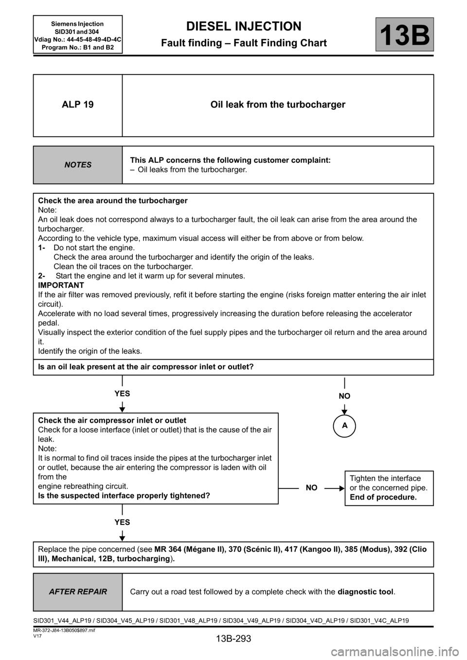
NOTighten the interface
or the concerned pipe.
End of procedure.
ALP 19 Oil leak from the turbocharger
NOTESThis ALP concerns the following customer complaint:
– Oil leaks from the turbocharger.
Check the area around the turbocharger
Note:
An oil leak does not correspond always to a turbocharger fault, the oil leak can arise from the area around the
turbocharger.
According to the vehicle type, maximum visual access will either be from above or from below.
1-Do not start the engine.
Check the area around the turbocharger and identify the origin of the leaks.
Clean the oil traces on the turbocharger.
2- Start the engine and let it warm up for several minutes.
IMPORTANT
If the air filter was removed previously, refit it before starting the engine (risks foreign matter entering the air inlet
circuit).
Accelerate with no load several times, progressively increasing the duration before releasing the accelerator
pedal.
Visually inspect the exterior condition of the fuel supply pipes and the turbocharger oil return and the area around
it.
Identify the origin of the leaks.
Is an oil leak present at the air compressor inlet or outlet?
YES
Check the air compressor inlet or outlet
Check for a loose interface (inlet or outlet) that is the cause of the air
leak.
Note:
It is normal to find oil traces inside the pipes at the turbocharger inlet
or outlet, because the air entering the compressor is laden with oil
from the
engine rebreathing circuit.
Is the suspected interface properly tightened?
YES
Replace the pipe concerned (see MR 364 (Mégane II), 370 (Scénic II), 417 (Kangoo II), 385 (Modus), 392 (Clio
III), Mechanical, 12B, turbocharging).
NO
AFTER REPAIRCarry out a road test followed by a complete check with the diagnostic tool.
SID301_V44_ALP19 / SID304_V45_ALP19 / SID301_V48_ALP19 / SID304_V49_ALP19 / SID304_V4D_ALP19 / SID301_V4C_ALP19
A
Page 313 of 329
13B-313
MR-372-J84-13B050$936.mif
V17
DIESEL INJECTION
Fault finding – Tests13B
Siemens Injection
SID301 and 304
Vdiag No.: 44-45-48-49-4D-4C
Program No.: B1 and B2
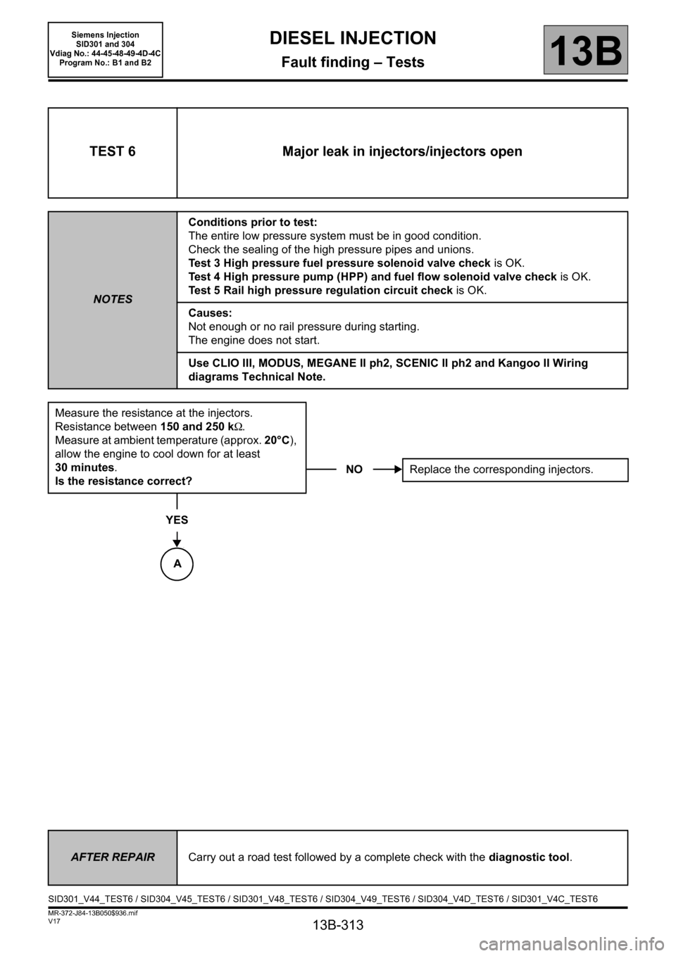
TEST 6 Major leak in injectors/injectors open
NOTESConditions prior to test:
The entire low pressure system must be in good condition.
Check the sealing of the high pressure pipes and unions.
Te s t 3 High pressure fuel pressure solenoid valve check is OK.
Test 4 High pressure pump (HPP) and fuel flow solenoid valve check is OK.
Te s t 5 Rail high pressure regulation circuit check is OK.
Causes:
Not enough or no rail pressure during starting.
The engine does not start.
Use CLIO III, MODUS, MEGANE II ph2, SCENIC II ph2 and Kangoo II Wiring
diagrams Technical Note.
Measure the resistance at the injectors.
Resistance between 150 and 250 kΩ.
Measure at ambient temperature (approx. 20°C),
allow the engine to cool down for at least
30 minutes.
Is the resistance correct?
YES
NOReplace the corresponding injectors.
AFTER REPAIRCarry out a road test followed by a complete check with the diagnostic tool.
SID301_V44_TEST6 / SID304_V45_TEST6 / SID301_V48_TEST6 / SID304_V49_TEST6 / SID304_V4D_TEST6 / SID301_V4C_TEST6
A
Page 314 of 329
13B-314
MR-372-J84-13B050$936.mif
V17
DIESEL INJECTION
Fault finding – Tests13B
Siemens Injection
SID301 and 304
Vdiag No.: 44-45-48-49-4D-4C
Program No.: B1 and B2
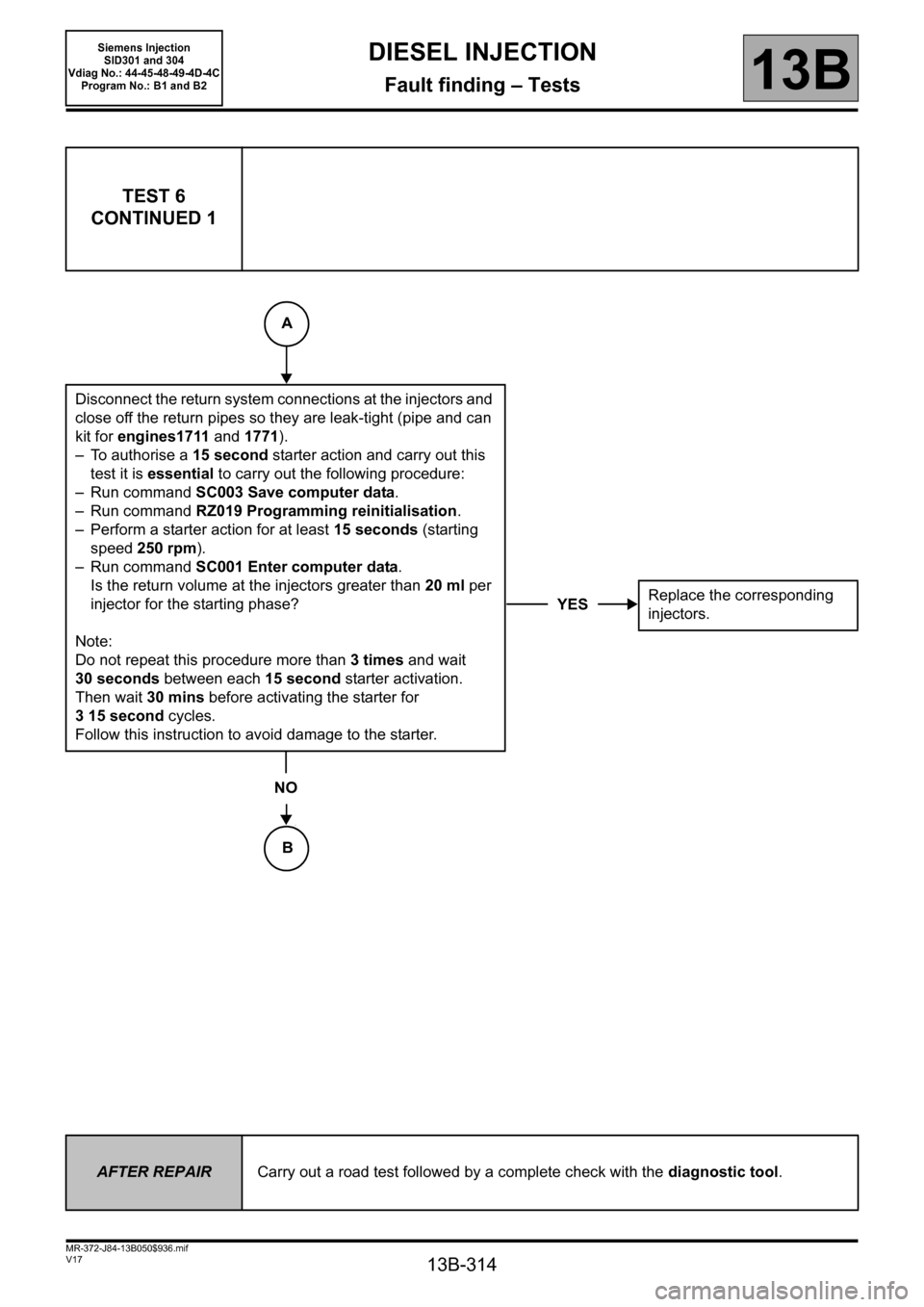
TEST 6
CONTINUED 1
Disconnect the return system connections at the injectors and
close off the return pipes so they are leak-tight (pipe and can
kit for engines1711 and 1771).
– To authorise a 15 second starter action and carry out this
test it is essential to carry out the following procedure:
– Run command SC003 Save computer data.
– Run command RZ019 Programming reinitialisation.
– Perform a starter action for at least 15 seconds (starting
speed 250 rpm).
– Run command SC001 Enter computer data.
Is the return volume at the injectors greater than 20 ml per
injector for the starting phase?
Note:
Do not repeat this procedure more than 3times and wait
30 seconds between each 15 second starter activation.
Then wait 30 mins before activating the starter for
315second cycles.
Follow this instruction to avoid damage to the starter.
NO
YESReplace the corresponding
injectors.
AFTER REPAIRCarry out a road test followed by a complete check with the diagnostic tool.
B
A
Page 315 of 329
13B-315
MR-372-J84-13B050$936.mif
V17
DIESEL INJECTION
Fault finding – Tests13B
Siemens Injection
SID301 and 304
Vdiag No.: 44-45-48-49-4D-4C
Program No.: B1 and B2
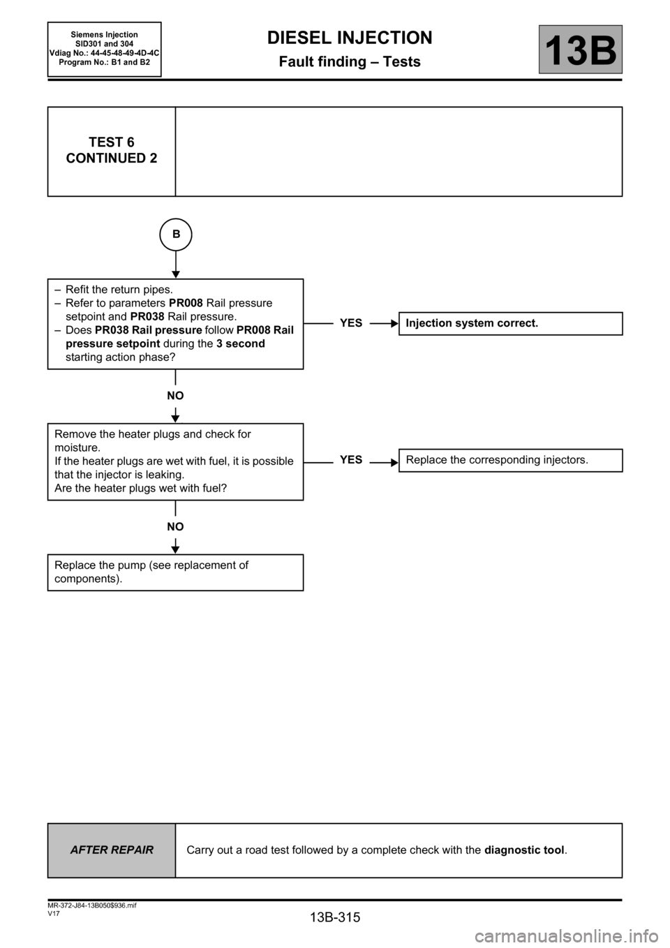
TEST 6
CONTINUED 2
– Refit the return pipes.
– Refer to parameters PR008 Rail pressure
setpoint and PR038 Rail pressure.
–Does PR038 Rail pressure follow PR008 Rail
pressure setpoint during the 3second
starting action phase?
NO
Remove the heater plugs and check for
moisture.
If the heater plugs are wet with fuel, it is possible
that the injector is leaking.
Are the heater plugs wet with fuel?
NO
Replace the pump (see replacement of
components).
YES Injection system correct.
YESReplace the corresponding injectors.
AFTER REPAIRCarry out a road test followed by a complete check with the diagnostic tool.
B