check engine RENAULT SCENIC 2011 J95 / 3.G Engine And Peripherals Siemens Injection Owner's Guide
[x] Cancel search | Manufacturer: RENAULT, Model Year: 2011, Model line: SCENIC, Model: RENAULT SCENIC 2011 J95 / 3.GPages: 329, PDF Size: 1.71 MB
Page 74 of 329
13B-74
MR-372-J84-13B050$429.mif
V17
DIESEL INJECTION
Fault finding – Interpretation of faults
Siemens Injection
SID301 and 304
Vdiag No.: 44-45-48-49-4D-4C
Program No.: B1 and B2
13B
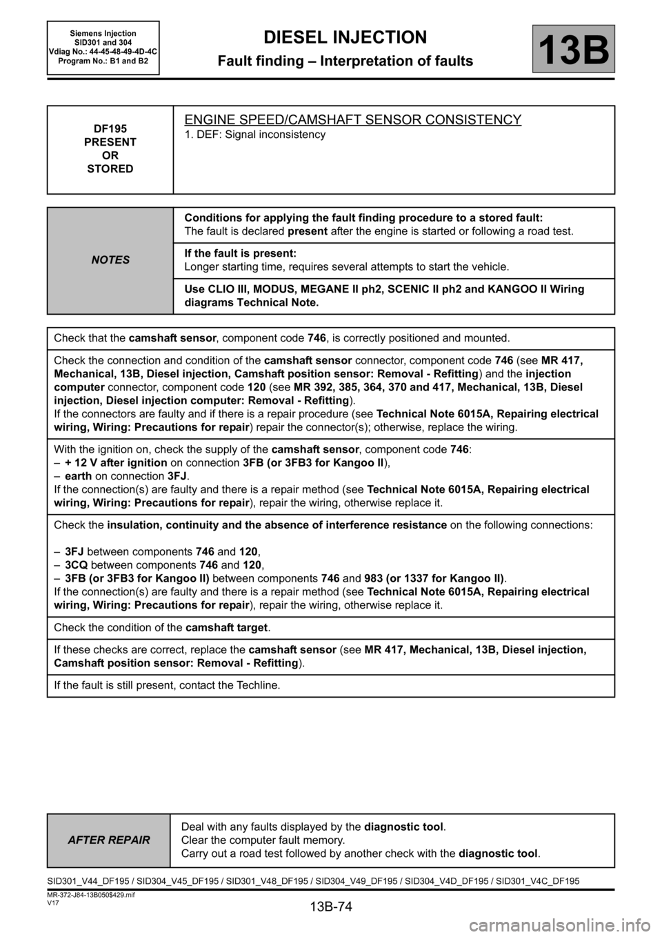
DF195
PRESENT
OR
STOREDENGINE SPEED/CAMSHAFT SENSOR CONSISTENCY
1. DEF: Signal inconsistency
NOTESConditions for applying the fault finding procedure to a stored fault:
The fault is declared present after the engine is started or following a road test.
If the fault is present:
Longer starting time, requires several attempts to start the vehicle.
Use CLIO III, MODUS, MEGANE II ph2, SCENIC II ph2 and KANGOO II Wiring
diagrams Technical Note.
Check that the camshaft sensor, component code 746, is correctly positioned and mounted.
Check the connection and condition of the camshaft sensor connector, component code 746 (see MR 417,
Mechanical, 13B, Diesel injection, Camshaft position sensor: Removal - Refitting) and the injection
computer connector, component code 120 (see MR 392, 385, 364, 370 and 417, Mechanical, 13B, Diesel
injection, Diesel injection computer: Removal - Refitting).
If the connectors are faulty and if there is a repair procedure (see Technical Note 6015A, Repairing electrical
wiring, Wiring: Precautions for repair) repair the connector(s); otherwise, replace the wiring.
With the ignition on, check the supply of the camshaft sensor, component code 746:
–+ 12 V after ignition on connection 3FB (or 3FB3 for Kangoo II),
–earth on connection 3FJ.
If the connection(s) are faulty and there is a repair method (see Technical Note 6015A, Repairing electrical
wiring, Wiring: Precautions for repair), repair the wiring, otherwise replace it.
Check the insulation, continuity and the absence of interference resistance on the following connections:
–3FJ between components 746 and 120,
–3CQ between components 746 and 120,
–3FB (or 3FB3 for Kangoo II) between components 746 and 983 (or 1337 for Kangoo II).
If the connection(s) are faulty and there is a repair method (see Technical Note 6015A, Repairing electrical
wiring, Wiring: Precautions for repair), repair the wiring, otherwise replace it.
Check the condition of the camshaft target.
If these checks are correct, replace the camshaft sensor
(see MR 417, Mechanical, 13B, Diesel injection,
Camshaft position sensor: Removal - Refitting).
If the fault is still present, contact the Techline.
AFTER REPAIRDeal with any faults displayed by the diagnostic tool.
Clear the computer fault memory.
Carry out a road test followed by another check with the diagnostic tool.
SID301_V44_DF195 / SID304_V45_DF195 / SID301_V48_DF195 / SID304_V49_DF195 / SID304_V4D_DF195 / SID301_V4C_DF195
Page 75 of 329
13B-75
MR-372-J84-13B050$429.mif
V17
DIESEL INJECTION
Fault finding – Interpretation of faults
Siemens Injection
SID301 and 304
Vdiag No.: 44-45-48-49-4D-4C
Program No.: B1 and B2
13B
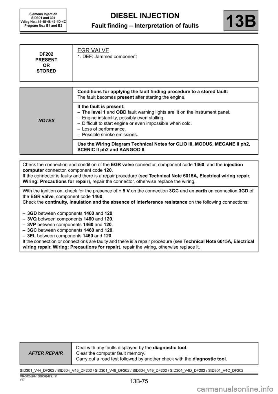
DF202
PRESENT
OR
STOREDEGR VALVE
1. DEF: Jammed component
NOTESConditions for applying the fault finding procedure to a stored fault:
The fault becomes present after starting the engine.
If the fault is present:
–The level 1 and OBD fault warning lights are lit on the instrument panel.
– Engine instability, possibly even stalling.
– Difficult to start engine or even impossible when cold.
– Loss of performance.
– Possible smoke emissions.
Use the Wiring Diagram Technical Notes for CLIO III, MODUS, MEGANE II ph2,
SCENIC II ph2 and KANGOO II.
Check the connection and condition of the EGR valve connector, component code 1460, and the injection
computer connector, component code 120.
If the connector is faulty and there is a repair procedure (see Technical Note 6015A, Electrical wiring repair,
Wiring: Precautions for repair), repair the connector, otherwise replace the wiring.
With the ignition on, check for the presence of + 5 V on the connection 3GC and an earth on connection 3GD of
the EGR valve, component code 1460.
Check the continuity, insulation and the absence of interference resistance on the following connections:
–3GD between components 1460 and 120,
–3VQ between components 1460 and 120,
–3VP between components 1460 and 120,
–3GC between components 1460 and 120,
–3EL between components 1460 and 120.
If the connection or connections are faulty and there is a repair procedure (see Technical Note 6015A, Electrical
wiring repair, Wiring: Precautions for repair), repair the wiring, otherwise replace it.
AFTER REPAIRDeal with any faults displayed by the diagnostic tool.
Clear the computer fault memory.
Carry out a road test followed by another check with the diagnostic tool.
SID301_V44_DF202 / SID304_V45_DF202 / SID301_V48_DF202 / SID304_V49_DF202 / SID304_V4D_DF202 / SID301_V4C_DF202
Page 76 of 329
13B-76
MR-372-J84-13B050$429.mif
V17
DIESEL INJECTION
Fault finding – Interpretation of faults
Siemens Injection
SID301 and 304
Vdiag No.: 44-45-48-49-4D-4C
Program No.: B1 and B2
13B
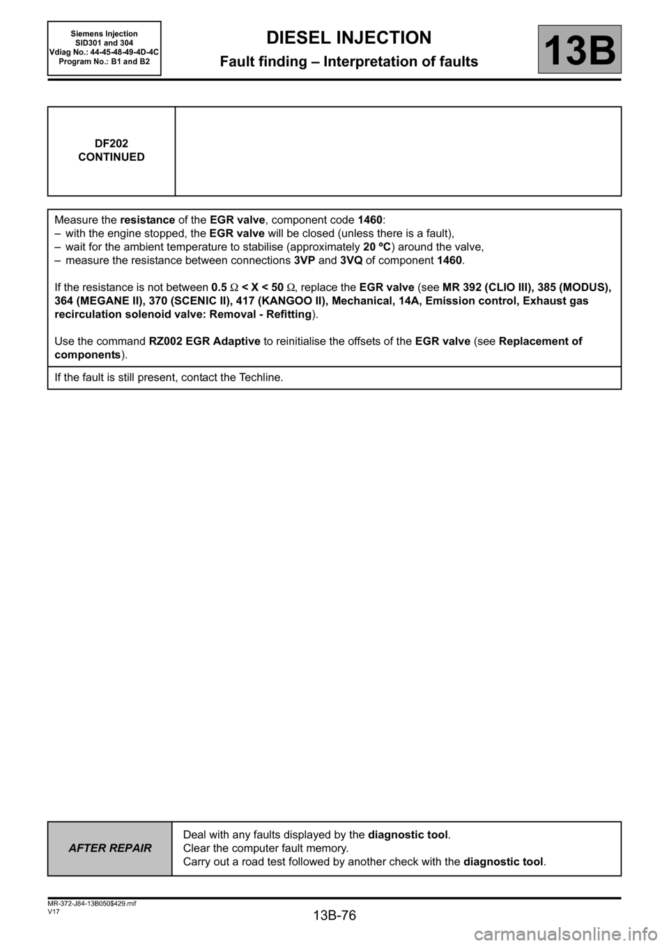
DF202
CONTINUED
Measure the resistance of the EGR valve, component code 1460:
– with the engine stopped, the EGR valve will be closed (unless there is a fault),
– wait for the ambient temperature to stabilise (approximately 20 ºC) around the valve,
– measure the resistance between connections3VP and 3VQ of component1460.
If the resistance is not between 0.5 Ω < X < 50 Ω, replace the EGR valve (see MR 392 (CLIO III), 385 (MODUS),
364 (MEGANE II), 370 (SCENIC II), 417 (KANGOO II), Mechanical, 14A, Emission control, Exhaust gas
recirculation solenoid valve: Removal - Refitting).
Use the command RZ002 EGR Adaptive to reinitialise the offsets of the EGR valve (see Replacement of
components).
If the fault is still present, contact the Techline.
AFTER REPAIRDeal with any faults displayed by the diagnostic tool.
Clear the computer fault memory.
Carry out a road test followed by another check with the diagnostic tool.
Page 77 of 329
13B-77
MR-372-J84-13B050$429.mif
V17
DIESEL INJECTION
Fault finding – Interpretation of faults
Siemens Injection
SID301 and 304
Vdiag No.: 44-45-48-49-4D-4C
Program No.: B1 and B2
13B
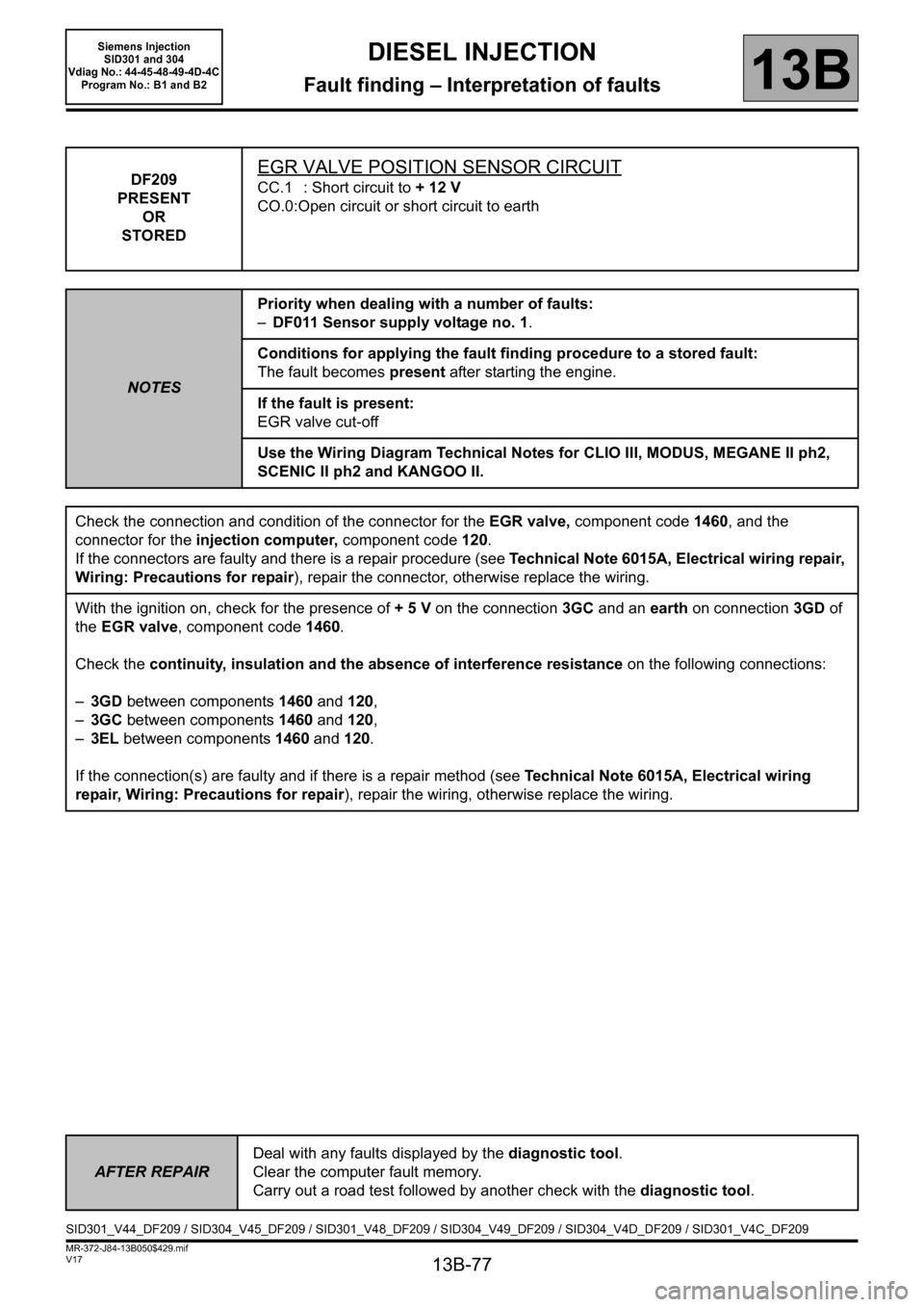
DF209
PRESENT
OR
STOREDEGR VALVE POSITION SENSOR CIRCUIT
CC.1 : Short circuit to + 12 V
CO.0:Open circuit or short circuit to earth
NOTESPriority when dealing with a number of faults:
–DF011 Sensor supply voltage no. 1.
Conditions for applying the fault finding procedure to a stored fault:
The fault becomes present after starting the engine.
If the fault is present:
EGR valve cut-off
Use the Wiring Diagram Technical Notes for CLIO III, MODUS, MEGANE II ph2,
SCENIC II ph2 and KANGOO II.
Check the connection and condition of the connector for the EGR valve, component code1460, and the
connector for the injection computer, component code120.
If the connectors are faulty and there is a repair procedure (see Technical Note 6015A, Electrical wiring repair,
Wiring: Precautions for repair), repair the connector, otherwise replace the wiring.
With the ignition on, check for the presence of + 5 V on the connection 3GC and an earth on connection 3GD of
the EGR valve, component code 1460.
Check the continuity, insulation and the absence of interference resistance on the following connections:
–3GD between components 1460 and 120,
–3GC between components 1460 and 120,
–3EL between components 1460 and 120.
If the connection(s) are faulty and if there is a repair method (see Technical Note 6015A, Electrical wiring
repair, Wiring: Precautions for repair), repair the wiring, otherwise replace the wiring.
AFTER REPAIRDeal with any faults displayed by the diagnostic tool.
Clear the computer fault memory.
Carry out a road test followed by another check with the diagnostic tool.
SID301_V44_DF209 / SID304_V45_DF209 / SID301_V48_DF209 / SID304_V49_DF209 / SID304_V4D_DF209 / SID301_V4C_DF209
Page 79 of 329
13B-79
MR-372-J84-13B050$429.mif
V17
DIESEL INJECTION
Fault finding – Interpretation of faults
Siemens Injection
SID301 and 304
Vdiag No.: 44-45-48-49-4D-4C
Program No.: B1 and B2
13B
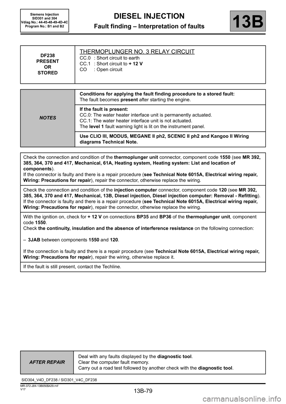
DF238
PRESENT
OR
STOREDTHERMOPLUNGER NO. 3 RELAY CIRCUIT
CC.0 : Short circuit to earth
CC.1 : Short circuit to + 12 V
CO : Open circuit
NOTESConditions for applying the fault finding procedure to a stored fault:
The fault becomes present after starting the engine.
If the fault is present:
CC.0: The water heater interface unit is permanently actuated.
CC.1: The water heater interface unit is not actuated.
The level 1 fault warning light is lit on the instrument panel.
Use CLIO III, MODUS, MEGANE II ph2, SCENIC II ph2 and Kangoo II Wiring
diagrams Technical Note.
Check the connection and condition of the thermoplunger unit connector, component code 1550 (see MR 392,
385, 364, 370 and 417, Mechanical, 61A, Heating system, Heating system: List and location of
components).
If the connector is faulty and there is a repair procedure (see Technical Note 6015A, Electrical wiring repair,
Wiring: Precautions for repair), repair the connector, otherwise replace the wiring.
Check the connection and condition of the injection computer connector, component code 120 (see MR 392,
385, 364, 370 and 417, Mechanical, 13B, Diesel injection, Diesel injection computer: Removal - Refitting).
If the connector is faulty and there is a repair procedure (see Technical Note 6015A, Electrical wiring repair,
Wiring: Precautions for repair), repair the connector, otherwise replace the wiring.
With the ignition on, check for + 12 V on connections BP35 and BP36 of the thermoplunger unit, component
code 1550.
Check the continuity, insulation and the absence of interference resistance on the following connection:
–3JAB between components1550 and 120.
If the connection is faulty and there is a repair procedure (see Technical Note 6015A, Electrical wiring repair,
Wiring: Precautions for repair), repair the wiring, otherwise replace it.
If the fault is still present, contact the Techline.
AFTER REPAIRDeal with any faults displayed by the diagnostic tool.
Clear the computer fault memory.
Carry out a road test followed by another check with the diagnostic tool.
SID304_V4D_DF238 / SID301_V4C_DF238
Page 80 of 329
13B-80
MR-372-J84-13B050$429.mif
V17
DIESEL INJECTION
Fault finding – Interpretation of faults
Siemens Injection
SID301 and 304
Vdiag No.: 44-45-48-49-4D-4C
Program No.: B1 and B2
13B
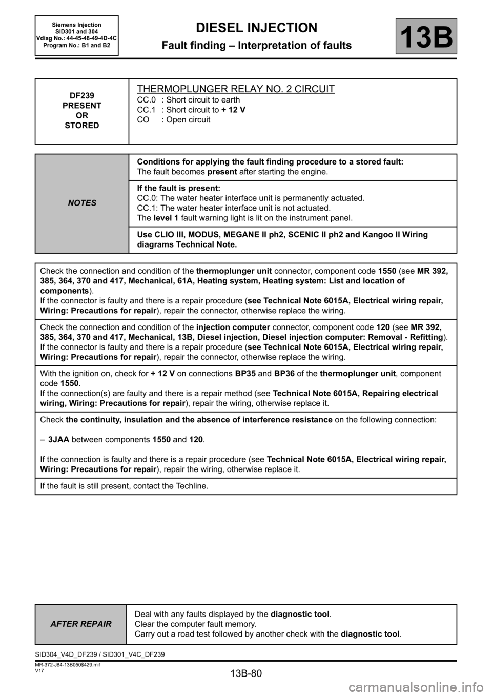
DF239
PRESENT
OR
STOREDTHERMOPLUNGER RELAY NO. 2 CIRCUIT
CC.0 : Short circuit to earth
CC.1 : Short circuit to + 12 V
CO : Open circuit
NOTESConditions for applying the fault finding procedure to a stored fault:
The fault becomes present after starting the engine.
If the fault is present:
CC.0: The water heater interface unit is permanently actuated.
CC.1: The water heater interface unit is not actuated.
The level 1 fault warning light is lit on the instrument panel.
Use CLIO III, MODUS, MEGANE II ph2, SCENIC II ph2 and Kangoo II Wiring
diagrams Technical Note.
Check the connection and condition of the thermoplunger unit connector, component code 1550 (see MR 392,
385, 364, 370 and 417, Mechanical, 61A, Heating system, Heating system: List and location of
components).
If the connector is faulty and there is a repair procedure (see Technical Note 6015A, Electrical wiring repair,
Wiring: Precautions for repair), repair the connector, otherwise replace the wiring.
Check the connection and condition of the injection computer connector, component code 120 (see MR 392,
385, 364, 370 and 417, Mechanical, 13B, Diesel injection, Diesel injection computer: Removal - Refitting).
If the connector is faulty and there is a repair procedure (see Technical Note 6015A, Electrical wiring repair,
Wiring: Precautions for repair), repair the connector, otherwise replace the wiring.
With the ignition on, check for + 12 V on connections BP35 and BP36 of the thermoplunger unit, component
code 1550.
If the connection(s) are faulty and there is a repair method (see Technical Note 6015A, Repairing electrical
wiring, Wiring: Precautions for repair), repair the wiring, otherwise replace it.
Check the continuity, insulation and the absence of interference resistance on the following connection:
–3JAA between components 1550 and 120.
If the connection is faulty and there is a repair procedure (see Technical Note 6015A, Electrical wiring repair,
Wiring: Precautions for repair), repair the wiring, otherwise replace it.
If the fault is still present, contact the Techline.
AFTER REPAIRDeal with any faults displayed by the diagnostic tool.
Clear the computer fault memory.
Carry out a road test followed by another check with the diagnostic tool.
SID304_V4D_DF239 / SID301_V4C_DF239
Page 81 of 329
13B-81
MR-372-J84-13B050$429.mif
V17
DIESEL INJECTION
Fault finding – Interpretation of faults
Siemens Injection
SID301 and 304
Vdiag No.: 44-45-48-49-4D-4C
Program No.: B1 and B2
13B
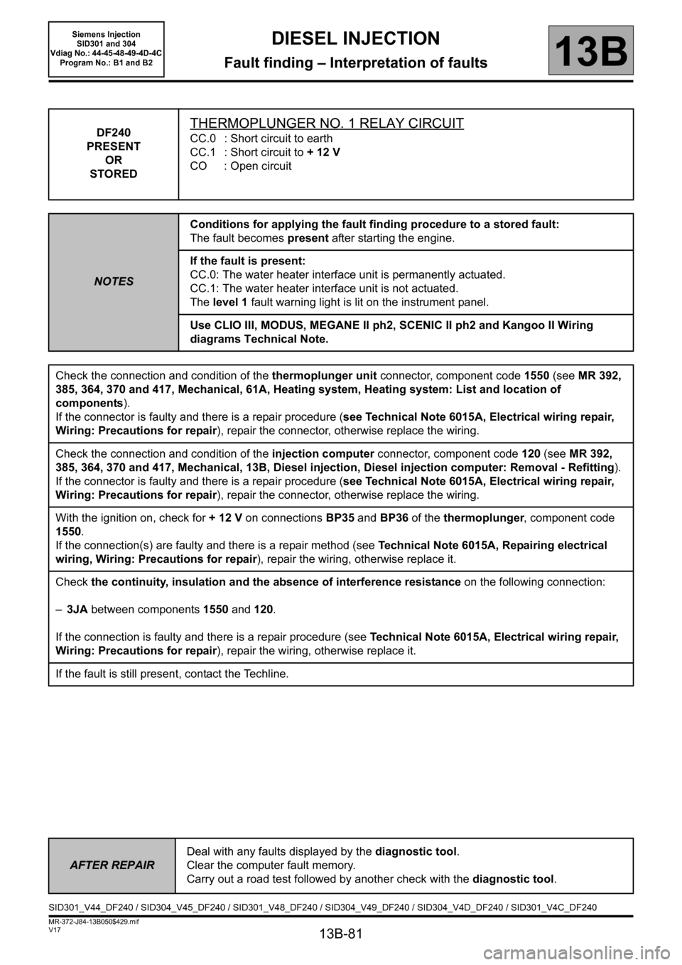
DF240
PRESENT
OR
STOREDTHERMOPLUNGER NO. 1 RELAY CIRCUIT
CC.0 : Short circuit to earth
CC.1 : Short circuit to + 12 V
CO : Open circuit
NOTESConditions for applying the fault finding procedure to a stored fault:
The fault becomes present after starting the engine.
If the fault is present:
CC.0: The water heater interface unit is permanently actuated.
CC.1: The water heater interface unit is not actuated.
The level 1 fault warning light is lit on the instrument panel.
Use CLIO III, MODUS, MEGANE II ph2, SCENIC II ph2 and Kangoo II Wiring
diagrams Technical Note.
Check the connection and condition of the thermoplunger unit connector, component code 1550 (see MR 392,
385, 364, 370 and 417, Mechanical, 61A, Heating system, Heating system: List and location of
components).
If the connector is faulty and there is a repair procedure (see Technical Note 6015A, Electrical wiring repair,
Wiring: Precautions for repair), repair the connector, otherwise replace the wiring.
Check the connection and condition of the injection computer connector, component code 120 (see MR 392,
385, 364, 370 and 417, Mechanical, 13B, Diesel injection, Diesel injection computer: Removal - Refitting).
If the connector is faulty and there is a repair procedure (see Technical Note 6015A, Electrical wiring repair,
Wiring: Precautions for repair), repair the connector, otherwise replace the wiring.
With the ignition on, check for + 12 V on connections BP35 and BP36 of the thermoplunger, component code
1550.
If the connection(s) are faulty and there is a repair method (see Technical Note 6015A, Repairing electrical
wiring, Wiring: Precautions for repair), repair the wiring, otherwise replace it.
Check the continuity, insulation and the absence of interference resistance on the following connection:
–3JA between components 1550 and 120.
If the connection is faulty and there is a repair procedure (see Technical Note 6015A, Electrical wiring repair,
Wiring: Precautions for repair), repair the wiring, otherwise replace it.
If the fault is still present, contact the Techline.
AFTER REPAIRDeal with any faults displayed by the diagnostic tool.
Clear the computer fault memory.
Carry out a road test followed by another check with the diagnostic tool.
SID301_V44_DF240 / SID304_V45_DF240 / SID301_V48_DF240 / SID304_V49_DF240 / SID304_V4D_DF240 / SID301_V4C_DF240
Page 82 of 329
13B-82
MR-372-J84-13B050$429.mif
V17
DIESEL INJECTION
Fault finding – Interpretation of faults
Siemens Injection
SID301 and 304
Vdiag No.: 44-45-48-49-4D-4C
Program No.: B1 and B2
13B
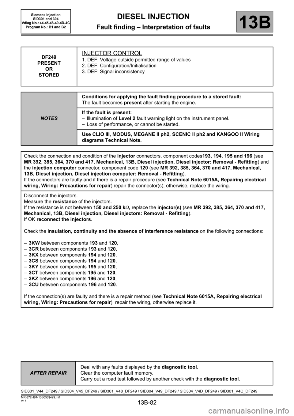
DF249
PRESENT
OR
STOREDINJECTOR CONTROL
1. DEF: Voltage outside permitted range of values
2. DEF: Configuration/Initialisation
3. DEF: Signal inconsistency
NOTESConditions for applying the fault finding procedure to a stored fault:
The fault becomes present after starting the engine.
If the fault is present:
– Illumination of Level 2 fault warning light on the instrument panel.
– Loss of performance, or cannot be started.
Use CLIO III, MODUS, MEGANE II ph2, SCENIC II ph2 and KANGOO II Wiring
diagrams Technical Note.
Check the connection and condition of the injector connectors, component codes193, 194, 195 and 196 (see
MR 392, 385, 364, 370 and 417, Mechanical, 13B, Diesel injection, Diesel injector: Removal - Refitting) and
the injection computer connector, component code 120 (see MR 392, 385, 364, 370 and 417, Mechanical,
13B, Diesel injection, Diesel injection computer: Removal - Refitting).
If the connectors are faulty and if there is a repair procedure (see Technical Note 6015A, Repairing electrical
wiring, Wiring: Precautions for repair) repair the connector(s); otherwise, replace the wiring.
Disconnect the injectors.
Measure the resistance of the injectors.
If the resistance is not between 150 and 250 kΩ, replace the injector(s) (see MR 392, 385, 364, 370 and 417,
Mechanical, 13B, Diesel injection, Diesel injectors: Removal - Refitting).
If OK reconnect the injectors.
Check the insulation, continuity and the absence of interference resistance on the following connections:
–3KW between components 193 and 120,
–3CR between components 193 and 120,
–3KX between components 194 and 120,
–3CS between components 194 and 120,
–3KY between components 195 and 120,
–3CT between components 195 and 120,
–3KZ between components
196 and 120,
–3CU between components 196 and 120.
If the connection(s) are faulty and there is a repair method (see Technical Note 6015A, Repairing electrical
wiring, Wiring: Precautions for repair), repair the wiring, otherwise replace it.
AFTER REPAIRDeal with any faults displayed by the diagnostic tool.
Clear the computer fault memory.
Carry out a road test followed by another check with the diagnostic tool.
SID301_V44_DF249 / SID304_V45_DF249 / SID301_V48_DF249 / SID304_V49_DF249 / SID304_V4D_DF249 / SID301_V4C_DF249
Page 84 of 329

13B-84
MR-372-J84-13B050$429.mif
V17
DIESEL INJECTION
Fault finding – Interpretation of faults
Siemens Injection
SID301 and 304
Vdiag No.: 44-45-48-49-4D-4C
Program No.: B1 and B2
13B
DF301
PRESENT
OR
STOREDAIR INLET CIRCUIT
1. DEF: Signal outside lower limit
2. DEF: Signal outside upper limit
NOTESConditions for applying the fault finding procedure to a stored fault:
The fault becomes present after starting the engine.
If the fault is present:
–The level 1 fault warning light is lit on the instrument panel.
– Loss of performance.
– EGR cut off.
– Turbocharging cut-off.
Use CLIO III, MODUS, MEGANE II ph2, SCENIC II ph2 and KANGOO II Wiring
diagrams Technical Note.
Carry out Te s t 1 0: Air Chain at the level of the turbocharger.
Carry out Te s t 11: Turbocharger control solenoid valve.
Carry out Test 12: Turbocharger.
Check the connection and condition of the turbocharging solenoid valve connector, component code 1475 and
the connector for the injection computer, component code 120.
If the connectors are faulty and there is a repair procedure (see Technical Note 6015A, Electrical wiring repair,
Wiring: Precautions for repair), repair the connector, otherwise replace the wiring.
With the ignition on, check for + 12 V after ignition feed on connection 3MG of the turbocharging solenoid valve,
component code 1475.
Check for + after ignition supply on connection 3FB1 (or 3FB3 for Kangoo II) of the turbocharging control
solenoid valve.
If the connection is faulty and there is a repair procedure (see Technical Note 6015A, Electrical wiring repair,
Wiring: Precautions for repair), repair the wiring, otherwise replace it.
Check the insulation, continuity and the absence of interference resistance of the following connection:
–3MG between components1475 and 120.
If the connection is faulty and there is a repair procedure (see Technical Note 6015A, Electrical wiring repair,
Wiring: Precautions for repair), repair the wiring, otherwise replace it.
If the fault is still present, contact the Techline.
AFTER REPAIRDeal with any faults displayed by the diagnostic tool.
Clear the computer fault memory.
Carry out a road test followed by another check with the diagnostic tool.
SID301_V44_DF301 / SID304_V45_DF301 / SID301_V48_DF301 / SID304_V49_DF301 / SID304_V4D_DF301 / SID301_V4C_DF301
Page 85 of 329
13B-85
MR-372-J84-13B050$429.mif
V17
DIESEL INJECTION
Fault finding – Interpretation of faults
Siemens Injection
SID301 and 304
Vdiag No.: 44-45-48-49-4D-4C
Program No.: B1 and B2
13B
*diff: differential
*temp: temperatureDF308
PRESENT
OR
STORED
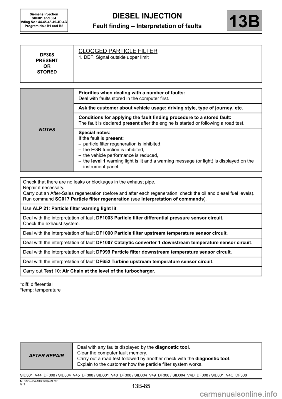
CLOGGED PARTICLE FILTER
1. DEF: Signal outside upper limit
NOTESPriorities when dealing with a number of faults:
Deal with faults stored in the computer first.
Ask the customer about vehicle usage: driving style, type of journey, etc.
Conditions for applying the fault finding procedure to a stored fault:
The fault is declared present after the engine is started or following a road test.
Special notes:
If the fault is present:
– particle filter regeneration is inhibited,
– the EGR function is inhibited,
– the vehicle performance is reduced,
– the level 1 warning light is lit and a warning message (or light) is displayed on the
instrument panel.
Check that there are no leaks or blockages in the exhaust pipe,
Repair if necessary.
Carry out an After-Sales regeneration (before and after each regeneration, check the oil and diesel fuel levels).
Run command SC017 Particle filter regeneration (see Interpretation of commands).
Use ALP 21: Particle filter warning light lit.
Deal with the interpretation of fault DF1003 Particle filter differential pressure sensor circuit.
Check the exhaust system.
Deal with the interpretation of fault DF1000 Particle filter upstream temperature sensor circuit.
Deal with the interpretation of fault DF1007 Catalytic converter 1 downstream temperature sensor circuit.
Deal with the interpretation of fault DF999 Particle filter downstream temperature sensor circuit.
Deal with the interpretation of fault DF652 Turbine upstream temperature sensor circuit.
Carry out Te s t 1 0: Air Chain at the level of the turbocharger.
AFTER REPAIRDeal with any faults displayed by the diagnostic tool.
Clear the computer fault memory.
Carry out a road test followed by another check with the diagnostic tool.
Explain to the customer how the particle filter system works.
SID301_V44_DF308 / SID304_V45_DF308 / SID301_V48_DF308 / SID304_V49_DF308 / SID304_V4D_DF308 / SID301_V4C_DF308