RENAULT TWINGO 2009 2.G Chasiss Workshop Manual
Manufacturer: RENAULT, Model Year: 2009, Model line: TWINGO, Model: RENAULT TWINGO 2009 2.GPages: 281
Page 241 of 281
37A-62
MECHANICAL COMPONENT CONTROLS
Clutch master cylinder: Removal - Refitting
JH3
37A
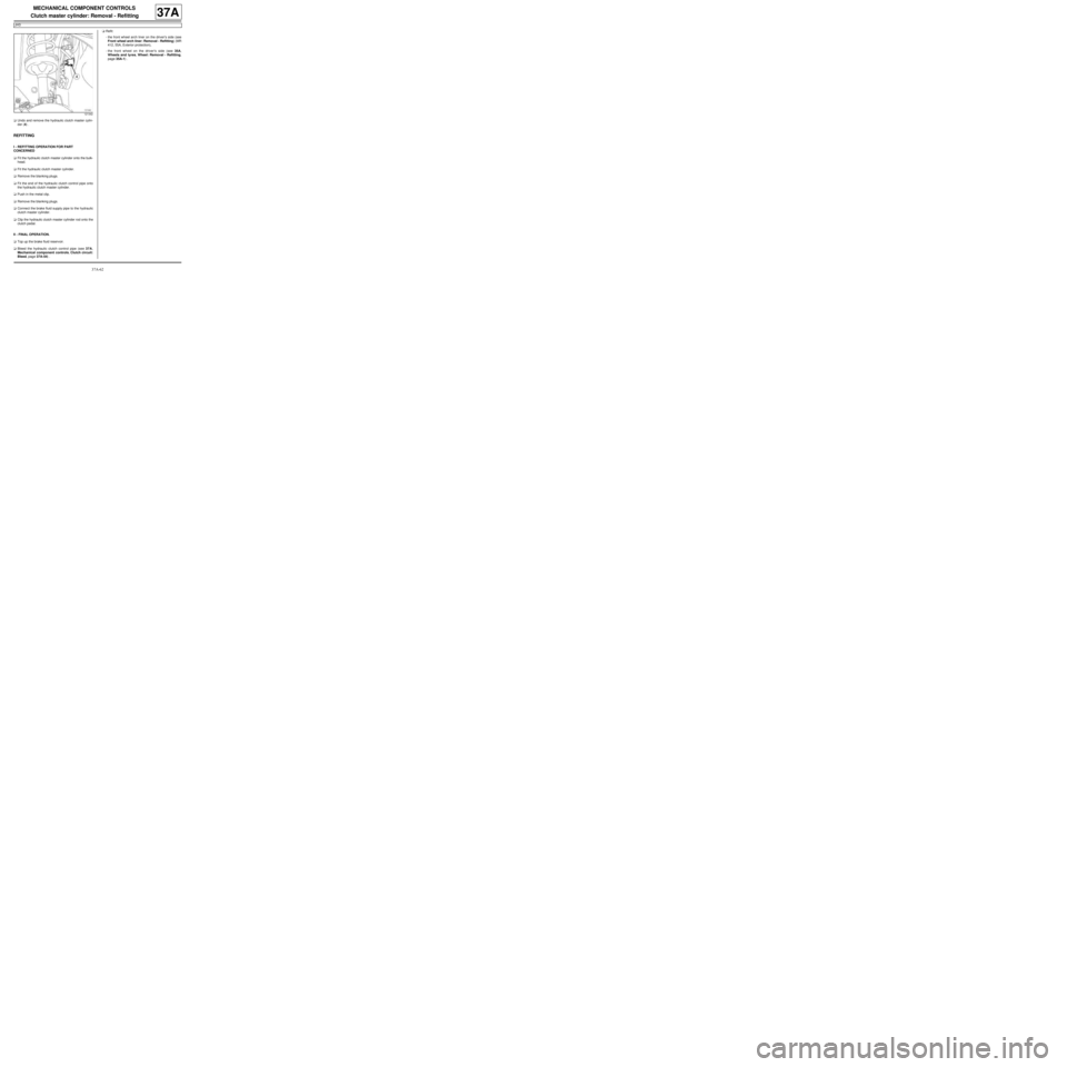
aUndo and remove the hydraulic clutch master cylin-
der (4) .
REFITTING
I - REFITTING OPERATION FOR PART
CONCERNED
aFit the hydraulic clutch master cylinder onto the bulk-
head.
aFit the hydraulic clutch master cylinder.
aRemove the blanking plugs.
aFit the end of the hydraulic clutch control pipe onto
the hydraulic clutch master cylinder.
aPush in the metal clip.
aRemove the blanking plugs.
aConnect the brake fluid supply pipe to the hydraulic
clutch master cylinder.
aClip the hydraulic clutch master cylinder rod onto the
clutch pedal.
II - FINAL OPERATION.
aTop up the brake fluid reservoir.
aBleed the hydraulic clutch control pipe (see 37A,
Mechanical component controls, Clutch circuit:
Bleed, page 37A-54) .aRefit:
-the front wheel arch liner on the driver's side (see
Front wheel arch liner: Removal - Refitting) (MR
412, 55A, Exterior protection),
-the front wheel on the driver's side (see 35A,
Wheels and tyres, Wheel: Removal - Refitting,
page 35A-1) .
121342
Page 242 of 281

37A-63
MECHANICAL COMPONENT CONTROLS
Clutch circuit: Removal - Refitting
JH3
37A
REMOVAL
I - REMOVAL PREPARATION OPERATION
aPosition the vehicle on a two-post lift (see Vehicle:
Towing and lifting) (MR 411, 02A, Lifting equip-
ment).
aRemove:
-the front wheel on the driver's side (see 35A,
Wheels and tyres, Wheel: Removal - Refitting,
page 35A-1) ,
-the front wheel arch liner on the driver's side (see
Front wheel arch liner: Removal - Refitting) (MR
412, 55A, Exterior protection),
-the battery (see Battery: Removal - Refitting)
(MR 411, 80A, Battery),
-the battery tray (see Battery tray: Removal - Re-
fitting) (MR 411, 80A, Battery).
aEmpty the brake fluid reservoir with a syringe.
II - OPERATION FOR REMOVAL OF PART
CONCERNED
aPress and hold the clip (1) .
aPull out the hydraulic clutch control pipe by one
notch.aPress and hold the clip (1) again.
aPull the hydraulic clutch control pipe out another
notch and collect the fluid in a container.
aDepress the clutch pedal to empty the hydraulic
clutch control circuit.
aDetach the pipe at (2) and (3) .
121354
WARNING
Prepare for the flow of fluid, and protect the sur-
rounding components.
121118
121114
Page 243 of 281
37A-64
MECHANICAL COMPONENT CONTROLS
Clutch circuit: Removal - Refitting
JH3
37A
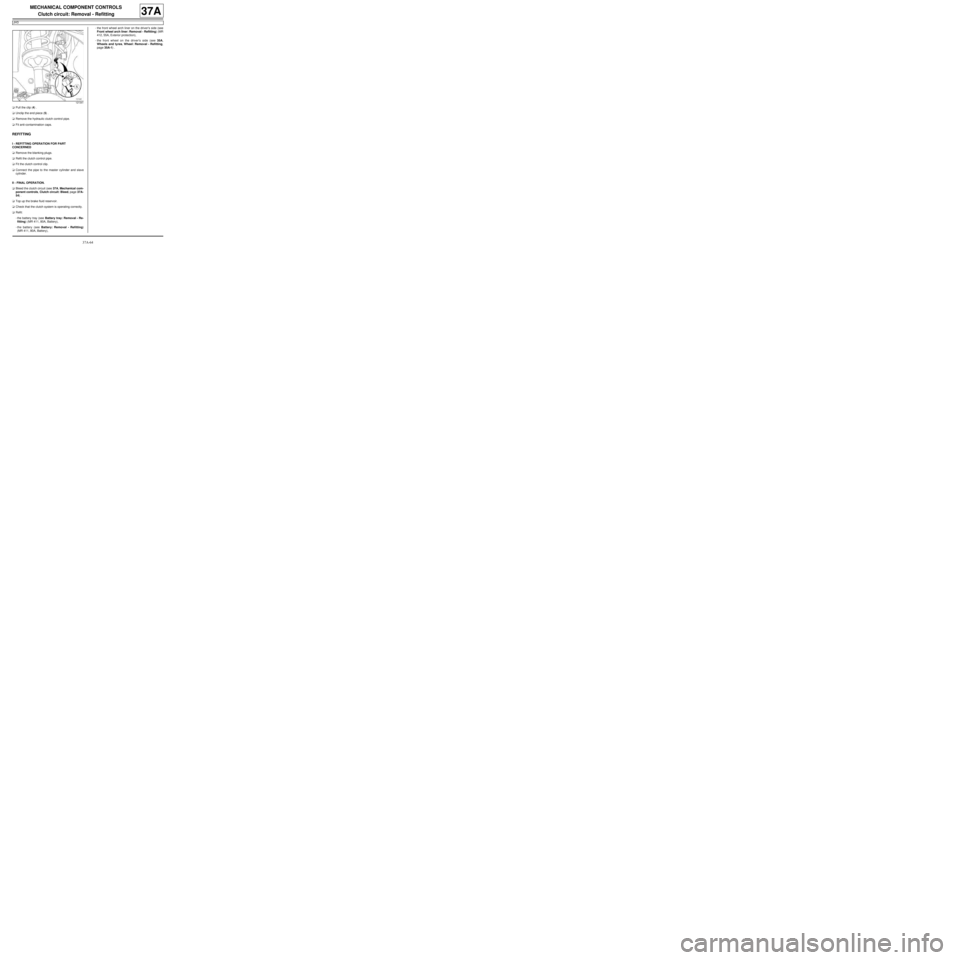
aPull the clip (4) .
aUnclip the end piece (5) .
aRemove the hydraulic clutch control pipe.
aFit anti-contamination caps.
REFITTING
I - REFITTING OPERATION FOR PART
CONCERNED
aRemove the blanking plugs.
aRefit the clutch control pipe.
aFit the clutch control clip.
aConnect the pipe to the master cylinder and slave
cylinder.
II - FINAL OPERATION.
aBleed the clutch circuit (see 37A, Mechanical com-
ponent controls, Clutch circuit: Bleed, page 37A-
54) .
aTop up the brake fluid reservoir.
aCheck that the clutch system is operating correctly.
aRefit:
-the battery tray (see Battery tray: Removal - Re-
fitting) (MR 411, 80A, Battery),
-the battery (see Battery: Removal - Refitting)
(MR 411, 80A, Battery),-the front wheel arch liner on the driver's side (see
Front wheel arch liner: Removal - Refitting) (MR
412, 55A, Exterior protection),
-the front wheel on the driver's side (see 35A,
Wheels and tyres, Wheel: Removal - Refitting,
page 35A-1) .
121341
Page 244 of 281
37A-65
MECHANICAL COMPONENT CONTROLS
Manual gear control: List and location of components
JB1
37A
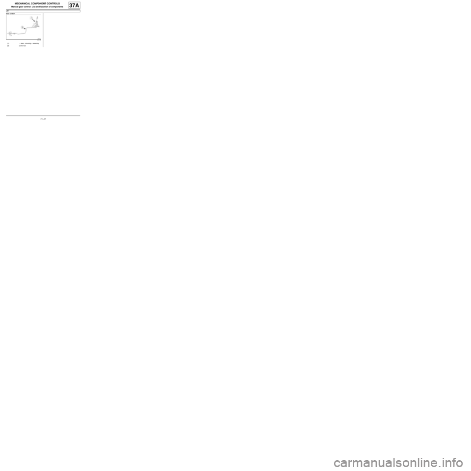
Gear control
121115
(1) « lever - mounting » assembly
(2) control bar
Page 245 of 281
37A-66
MECHANICAL COMPONENT CONTROLS
Manual gear control: List and location of components
JH3
37A
Gear control
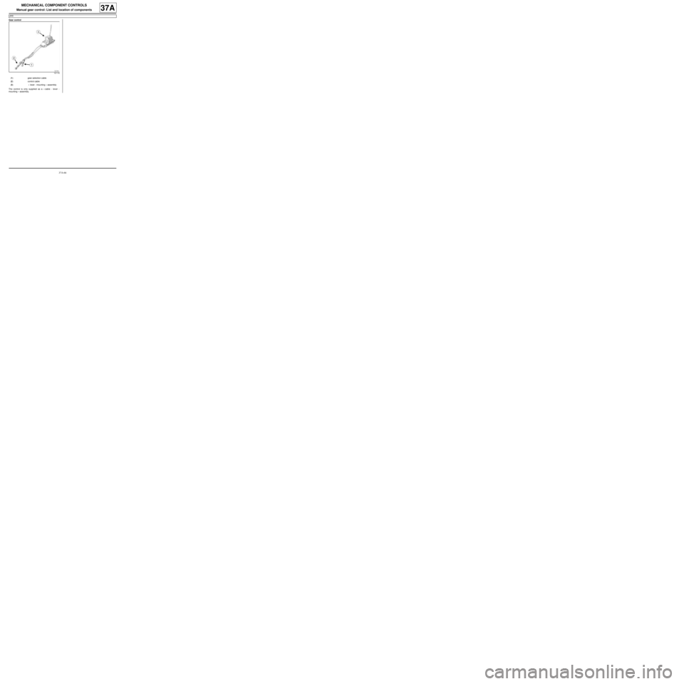
The control is only supplied as a « cable - lever -
mounting » assembly.
121116
(1) gear selection cable
(2) control cable
(3) « lever - mounting » assembly
Page 246 of 281
37A-67
MECHANICAL COMPONENT CONTROLS
Gear control unit: Removal - Refitting
JH3 or JR5
37A
REMOVAL
I - REMOVAL PREPARATION OPERATION
aPosition the vehicle on a two-post lift (see Vehicle:
Towing and lifting) (02A, Lifting equipment).
aRemove the centre console (see Centre console:
Removal - Refitting) (57A, Interior equipment).
aRemove:
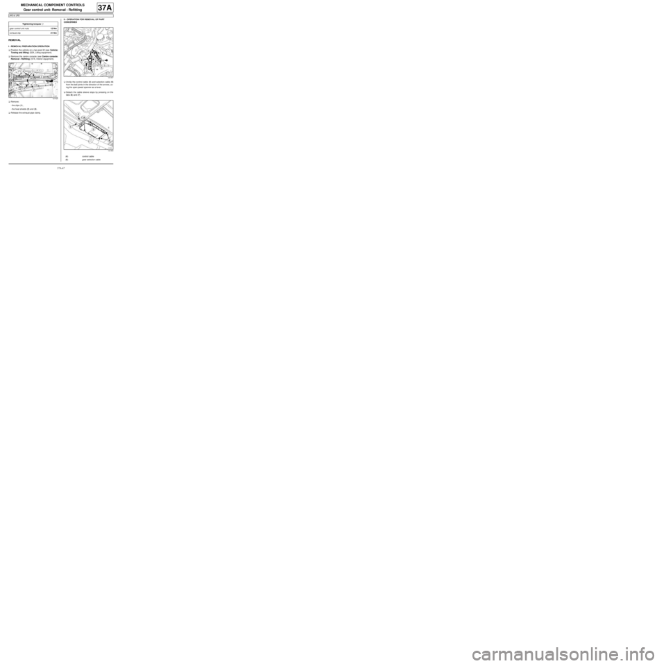
-the clips (1) ,
-the heat shields (2) and (3) .
aRelease the exhaust pipe clamp.II - OPERATION FOR REMOVAL OF PART
CONCERNED
aUnclip the control cable (4) and selection cable (5)
from the ball joints in the direction of the arrows, us-
ing the open-jawed spanner as a lever.
aDetach the cable sleeve stops by pressing on the
tabs (6) and (7) . Tightening torquesm
gear control unit nuts12 Nm
exhaust clip21 Nm
121425
121357
121363
(4) control cable
(5) gear selection cable
Page 247 of 281
37A-68
MECHANICAL COMPONENT CONTROLS
Gear control unit: Removal - Refitting
JH3 or JR5
37A
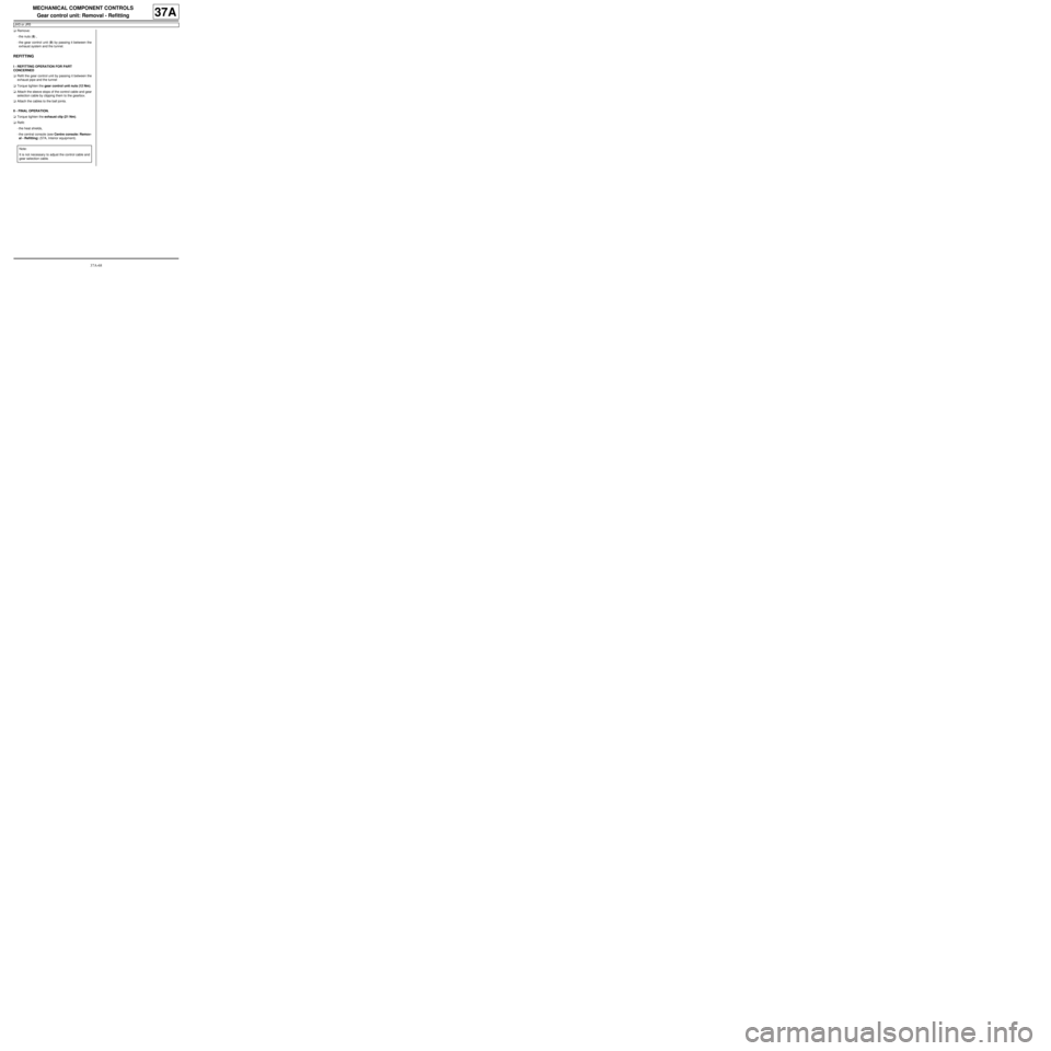
aRemove:
-the nuts (8) ,
-the gear control unit (9) by passing it between the
exhaust system and the tunnel.
REFITTING
I - REFITTING OPERATION FOR PART
CONCERNED
aRefit the gear control unit by passing it between the
exhaust pipe and the tunnel
aTorque tighten the gear control unit nuts (12 Nm).
aAttach the sleeve stops of the control cable and gear
selection cable by clipping them to the gearbox.
aAttach the cables to the ball joints.
II - FINAL OPERATION.
aTorque tighten the exhaust clip (21 Nm).
aRefit:
-the heat shields,
-the central console (see Centre console: Remov-
al - Refitting) (57A, Interior equipment).
Note:
It is not necessary to adjust the control cable and
gear selection cable.
Page 248 of 281
37A-69
MECHANICAL COMPONENT CONTROLS
Gear control unit: Removal - Refitting
JB1
37A
REMOVAL
I - REMOVAL PREPARATION OPERATION
aPosition the vehicle on a two-post lift (see Vehicle:
Towing and lifting) (MR 411, 02A, Lifting equip-
ment).
aRemove:
-the centre console (see Centre console: Removal
- Refitting) (MR 412, 57A, Interior equipment),
-the catalytic converter (see Catalytic converter:
Removal - Refitting) (MR 411, 19B, Exhaust).
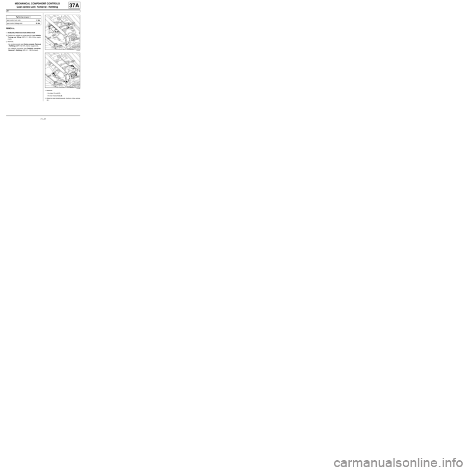
aRemove:
-the clips (1) and (2) ,
-the rear heat shield (3) .
aSlide the heat shield towards the front of the vehicle
(4) . Tightening torquesm
gear control unit nuts12 Nm
gear control linkage bolt28 Nm
121327
121328
Page 249 of 281
37A-70
MECHANICAL COMPONENT CONTROLS
Gear control unit: Removal - Refitting
JB1
37A
II - OPERATION FOR REMOVAL OF PART
CONCERNED
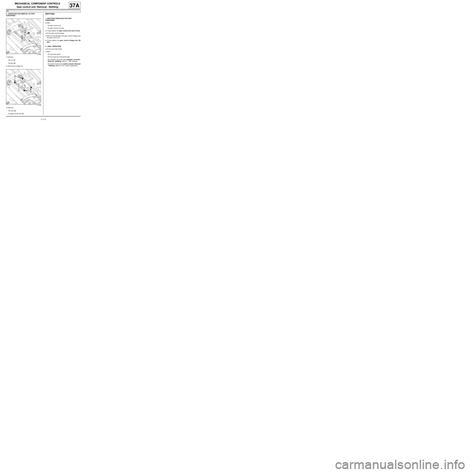
aRemove:
-the nut (5) ,
-the bolt (6) .
aRemove the linkage (7) .
aRemove:
-the nuts (8) ,
-the gear control unit (9) .REFITTING
I - REFITTING OPERATION FOR PART
CONCERNED
aRefit:
-the gear control unit,
-the gear control unit nuts.
aTorque tighten the gear control unit nuts (12 Nm).
aFit the gear control linkage.
aRefit the bolt between the gear control linkage and
the gear control unit.
aTorque tighten the gear control linkage bolt (28
Nm ).
II - FINAL OPERATION.
aFit the front heat shield.
aRefit:
-the rear heat shield,
-the front and rear heat shield clips,
-the catalytic converter (see Catalytic converter:
Removal - Refitting) (MR 411, 19B, Exhaust),
-the centre console (see Centre console: Removal
- Refitting) (MR 412, 57A, Interior equipment).
121337
121336
Page 250 of 281
37A-71
MECHANICAL COMPONENT CONTROLS
Gear control unit: Adjustment
JB1
37A
ADJUSTMENT
I - ADJUSTMENT PREPARATION STAGE
aPosition the vehicle on a two-post lift (see Vehicle:
Towing and lifting) (MR 411, 02A, Lifting equip-
ment).
aEngage first gear.
aRemove:
-the clips (1) ,
-the heat shield (2) .II - OPERATION FOR ADJUSTMENT OF PART
CONCERNED
aUnlock the nut (3) . Special tooling required
Bvi. 1133-011st gear locking shim for
gearbox input lever.
Tightening torquesm
linkage adjusting nut30 Nm
121327
121339