Valve RENAULT TWINGO 2009 2.G Engine And Peripherals Owner's Guide
[x] Cancel search | Manufacturer: RENAULT, Model Year: 2009, Model line: TWINGO, Model: RENAULT TWINGO 2009 2.GPages: 652
Page 234 of 652
11A-117
TOP AND FRONT OF ENGINE
Cylinder head: Removal - Refitting
K9K
11A
aIf necessary, carry out a complete check of the cylin-
der head (see Cylinder head: Check) .
II - REFITTING OPERATION FOR PART
CONCERNED
aBring the pistons to mid-stroke position to prevent
them from coming into contact with the valves during
the tightening of the cylinder head.
aRefit:
-a new cylinder head gasket,
-the cylinder head.
Cylinder head tightening procedure
aRefit the cylinder head bolts.
aFit the cylinder head bolts, without tightening them.
aTighten to torque and in order the cylinder head
bolts (initial torque) (25 N.m).
aCheck that the cylinder head bolts are tightened to
25 Nm.
aAngle tighten the cylinder head bolts (270˚ ±± ± ±
10˚) in
order using a cylinder head bolt tightening gauge
(angular measuring type).
III - FINAL OPERATION
aRefit:
-the timing end bracket on the air filter box.
-the timing end bracket bolt on the air filter box,-the two high pressure pipes between the rail and
injector at the timing end (see 13B, Diesel injec-
tion, High pressure pipe between rail and injec-
tor: Removal - Refitting, page 13B-39) ,
-the rocker cover (see 11A, Top and front of en-
gine, Rocker cover: Removal - Refitting, page
11A-66) ,
-the oil return pipe fitted with new seals, fitting it into
the cylinder block (see 12B, Turbocharging, Tur-
bocharger oil pipe: Removal - Refitting, page
12B-12) .
aRefit the catalytic converter (see 19B, Exhaust,
Catalytic converter: Removal - Refitting, page
19B-12) .
aConnect:
-the coolant temperature sensor connector,
-the heater matrix cooling hose to the water cham-
ber.
aFit the clip on the heater matrix cooling hose onto
the water chamber using the (Mot. 1202-01) or
(Mot. 1202-02) or (Mot. 1448).
aConnect the coolant pump inlet pipe cooling hose.
aFit the cooling hose clip at the coolant pump inlet
pipe end using the (Mot. 1202-01) or (Mot. 1202-02)
or (Mot. 1448).
aConnect the EGR cooler cooling hose.
aFit the cooling hose clip at the EGR cooler end using
the (Mot. 1202-01) or (Mot. 1202-02) or (Mot.
1448).
aConnect the brake servo pipe onto the vacuum
pump.
aFit the engine wiring.
aClip:
-the breather pipe onto the gearbox,
-the wiring on the engine lifting eye on the gearbox
side.
aRefit the air filter unit (see 12A, Fuel mixture, Air fil-
ter unit: Removal - Refitting, page 12A-13) .
aRemove the blanking plugs from the fuel pipes and
high pressure pump.
aConnect the fuel inlet and return pipes to the high
pressure pump.
aFit the engine wiring.
aConnect:
-the accelerometer connector,
-injector rail pressure sensor connector, WARNING
In order to ensure that the bolts are correctly
tightened, use a syringe to remove any oil which
may be in the cylinder head mounting holes.
19712
Page 236 of 652
11A-119
TOP AND FRONT OF ENGINE
Cylinder head: Removal - Refitting
K4M
11A
REMOVAL
I - REMOVAL PREPARATION OPERATION
aPosition the vehicle on a two-post lift (see Vehicle:
Towing and lifting) (02A, Lifting equipment).
aDisconnect the battery (see Battery: Removal - Re-
fitting) (80A, Battery).
aRemove the engine undertray.
aDrain the cooling system (see 19A, Cooling, Cool-
ing system: Draining - Refilling, page 19A-9) .
aRemove:
-the windscreen wiper arms (see Windscreen wip-
er arm: Removal - Refitting) (85A, Wiping -
Washing),
-the scuttle panel grille (see Scuttle panel grille:
Removal - Refitting) (56A, Exterior equipment),
-the scoop under the scuttle panel grille (see Scoop
under the scuttle panel grille: Removal - Refit-
ting) (56A, Exterior equipment),
-the coils (see 17A, Ignition, Coils: Removal - Re-
fitting, page 17A-1) ,-the throttle valve (see 12A, Fuel mixture, Throttle
valve: Removal - Refitting, page 12A-20) ,
-the inlet distributor (see 12A, Fuel mixture, Inlet
distributor: Removal - Refitting, page 12A-29) ,
-the oil decanter (see 11A, Top and front of en-
gine, Oil decanter: Removal - Refitting, page
11A-147) ,
-the front right-hand wheel (see Wheel: Removal -
Refitting) (35A, Wheels and tyres),
-the front right-hand wheel arch liner (see Front
wheel arch liner: Removal - Refitting) (55A, Ex-
terior protection),
-the front bumper (see Front bumper: Removal -
Refitting) (55A, Exterior protection),
-the headlights (see Halogen headlight: Removal
- Refitting) (80B, Headlights),
-the bonnet catch (see Bonnet lock: Removal -
Refitting) (52A, Non-side opening element mecha-
nisms),
-the front upper cross member (see Front upper
cross member: Removal - Refitting) (42A, Upper
front structure),
-the accessories belt (see 11A, Top and front of
engine, Accessories belt: Removal - Refitting,
page 11A-3) ,
-the air filter unit (see 12A, Fuel mixture, Air filter
unit: Removal - Refitting, page 12A-13) ,
-the lower engine tie-bar (see 19D, Engine mount-
ing, Lower engine tie-bar: Removal - Refitting,
page 19D-18) ,
-the right-hand suspended engine mounting (see
19D, Engine mounting, Right-hand suspended
engine mounting: Removal - Refitting, page
19D-13) ,
-the crankshaft accessories pulley (see 11A, Top
and front of engine, Crankshaft accessories
pulley: Removal - Refitting, page 11A-20) ,
-the timing belt (see 11A, Top and front of engine,
Timing belt: Removal - Refitting, page 11A-27) ,
-the camshaft dephaser (see 11A, Top and front of
engine, Camshaft dephaser: Removal - Refit-
ting, page 11A-135) ,
-the camshaft seals on the timing end (see 11A,
Top and front of engine, Camshaft seal, timing
end: Removal - Refitting, page 11A-138) ,
-the rocker cover (see 11A, Top and front of en-
gine, Rocker cover: Removal - Refitting, page
11A-66) , Special tooling required
Mot. 1448Remote operation pliers for
hose clips .
Mot. 1202-01Clip pliers for hose clips
(large size).
Mot. 1202-02Clip pliers for hose clips
(small size)
Tightening torquesm
cylinder head bolts (ini-
tial torque)20 N.m
cylinder head bolts240˚ ±± ± ±
6˚
IMPORTANT
Wear cut-resistant gloves during the operation.
IMPORTANT
Wear leaktight gloves (Nitrile type) for this opera-
tion.
Page 241 of 652
11A-124
TOP AND FRONT OF ENGINE
Cylinder head: Removal - Refitting
K4M
11A
-the right-hand suspended engine mounting (see
19D, Engine mounting, Right-hand suspended
engine mounting: Removal - Refitting, page
19D-13) ,
-the lower engine tie-bar (see 19D, Engine mount-
ing, Lower engine tie-bar: Removal - Refitting,
page 19D-18) ,
-the air filter unit (see 12A, Fuel mixture, Air filter
unit: Removal - Refitting, page 12A-13) ,
-the accessories belt (see 11A, Top and front of
engine, Accessories belt: Removal - Refitting,
page 11A-3) ,
-the front upper cross member (see Front upper
cross member: Removal - Refitting) (42A, Upper
front structure),
-the bonnet catch (see Bonnet lock: Removal -
Refitting) (52A, Non-side opening element mecha-
nisms),
-the headlights (see Halogen headlight: Removal
- Refitting) (80B, Headlights),
-the front bumper (see Front bumper: Removal -
Refitting) (55A, Exterior protection),
-the front right-hand wheel arch liner (see Front
wheel arch liner: Removal - Refitting) (55A, Ex-
terior protection),
-the front right-hand wheel (see Wheel: Removal -
Refitting) (35A, Wheels and tyres),
-the oil decanter (see 11A, Top and front of en-
gine, Oil decanter: Removal - Refitting, page
11A-147) ,
-the inlet distributor (see 12A, Fuel mixture, Inlet
distributor: Removal - Refitting, page 12A-29) ,
-the throttle valve (see 12A, Fuel mixture, Throttle
valve: Removal - Refitting, page 12A-20) ,
-the coils (see 17A, Ignition, Coils: Removal - Re-
fitting, page 17A-1) ,
-the scoop under the scuttle panel grille (see Scoop
under the scuttle panel grille: Removal - Refit-
ting) (56A, Exterior equipment),
-the scuttle panel grille (see Scuttle panel grille:
Removal - Refitting) (56A, Exterior equipment),
-the windscreen wiper arms (see Windscreen wip-
er arm: Removal - Refitting) (85A, Wiping -
Washing).
aPerform the following operations:
-fill the gearbox (see Manual gearbox oils: Drain-
ing - Filling) (21A, Manual gearbox).-fill and bleed the coolant circuit (see 19A, Cooling,
Cooling system: Draining - Refilling, page 19A-
9) .
aRefit the engine undertray.
aConnect the battery (see Battery: Removal - Refit-
ting) (80A, Battery).
Page 244 of 652
11A-127
TOP AND FRONT OF ENGINE
Cylinder head: Removal - Refitting
D7F – D4F, and 772
11A
1 - Cleaning the cylinder head
aApply SUPER CLEANER FOR JOINT FACES (see
Vehicle: Parts and consumables for the repair)
(04B, Consumables - Products) to the areas to be
cleaned.
aWait for approximately ten minutes.
aRemove the residue using a wooden spatula.
aComplete the cleaning operation using a grey abra-
sive pad.
2 - Checking the gasket face
aCheck the flatness of the cylinder head gasket face
(see Cylinder head: Check) .3 - Optional additional operations
aWhen replacing the cylinder head, strip the cylinder
head (see Cylinder head: Stripping - Rebuilding) .
aIf necessary, carry out a complete check of the cylin-
der head (see Cylinder head: Check) .
II - REFITTING OPERATION FOR PART
CONCERNED
aBring the pistons to mid-stroke position to prevent
them from coming into contact with the valves during
the tightening of the cylinder head.
aCheck for the cylinder head centring dowels on the
cylinder block.
aRefit:
-a new cylinder head gasket,
-the cylinder head.
Cylinder head tightening procedure
aRefit the new cylinder head bolts.
aFit the cylinder head bolts, without tightening them. WARNING
Do not scrape the joint faces of the aluminium,
any damage caused to the joint face will result in
a risk of leaks.
WARNING
Do not allow this product to drip onto the paint-
work.
Clean the cylinder head carefully to avoid any
foreign bodies entering the oil return and supply
pipes.
Failure to follow this advice could lead to the
blocking of the various oil inlet galleries, which
would quickly result in engine damage.
WARNING
Protect the oilway so that foreign bodies do not
enter the oil pipes in the cylinder head.
Failure to follow this instruction could lead to the
blocking of the oilways, resulting in a rapid deteri-
oration of the camshaft.
Note:
The cylinder head bolts must not be lubricated
before being fitted.
WARNING
No regrinding of the cylinder head is permitted.
WARNING
In order to ensure that the bolts are correctly
tightened, use a syringe to remove any oil which
may be in the cylinder head mounting holes.
Page 248 of 652
11A-131
TOP AND FRONT OF ENGINE
Cylinder head: Removal - Refitting
D4F, and 780 or 782
11A
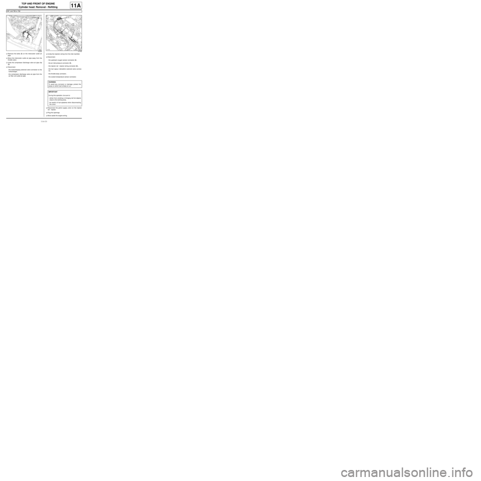
aRemove the bolts (2) on the intercooler outlet air
pipe.
aMove the intercooler outlet air pipe away from the
throttle valve.
aUndo the compressor discharge valve air pipe clip
(3) .
aDisconnect:
-the turbocharging solenoid valve connector to the
turbocharger,
-the compressor discharge valve air pipe from the
air filter unit outlet air pipe.aUnclip the injection wiring from the inlet manifold.
aDisconnect:
-the upstream oxygen sensor connector (4) .
-the air inlet pressure connector (5) ,
-the injector rail - injector wiring connector (6) ,
-the fuel vapour rebreather solenoid valve connec-
tor,
-the throttle body connector ,
-the coolant temperature sensor connector.
aDisconnect the petrol supply union on the injector
rail - injector.
aPlug the openings.
aMove aside the engine wiring.
122390121765
WARNING
To avoid any corrosion or damage, protect the
areas on which fuel is likely to r un.
IMPORTANT
Dur ing this operation, be sure to:
-refrain from smoking or bringing red hot objects
close to the working area,
-be careful of fuel splashes when disconnecting
the union.
Page 250 of 652
11A-133
TOP AND FRONT OF ENGINE
Cylinder head: Removal - Refitting
D4F, and 780 or 782
11A
2 - Checking the gasket face
aCheck the flatness of the cylinder head gasket face
(see Cylinder head: Check) .
3 - Optional additional operations
aWhen replacing the cylinder head, strip the cylinder
head (see Cylinder head: Stripping - Rebuilding) .
aIf necessary, carry out a complete check of the cylin-
der head (see Cylinder head: Check) .
II - REFITTING OPERATION FOR PART
CONCERNED
aBring the pistons to mid-stroke position to prevent
them from coming into contact with the valves during
the tightening of the cylinder head.
aCheck for the cylinder head centring dowels on the
cylinder block.
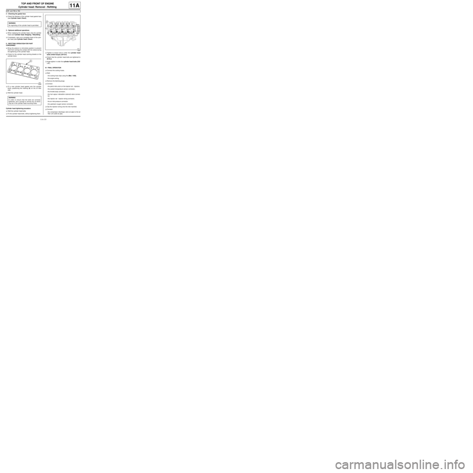
aFit a new cylinder head gasket onto the cylinder
block, positioning the marking (8) on the oil filter
side.
aRefit the cylinder head.
Cylinder head tightening procedure
aRefit the cylinder head bolts.
aFit the cylinder head bolts, without tightening them.aTighten to torque and in order the cylinder head
bolts (initial torque) (20 N.m).
aCheck that the cylinder head bolts are tightened to
20 N.m.
aAngle tighten in order the cylinder head bolts (230˚
±± ± ±
6˚).
III - FINAL OPERATION
aConnect the cooling hoses.
aRefit:
-the cooling hose clips using the (Mot. 1448),
-the engine wiring.
aRemove the blanking plugs.
aConnect:
-the petrol inlet union on the injector rail - injectors.
-the coolant temperature sensor connector,
-the throttle body connector ,
-the fuel vapour rebreather solenoid valve connec-
tor,
-the injector rail - injector wiring connector,
-the air inlet pressure connector.
-the upstream oxygen sensor connector.
aClip the injection wiring onto the inlet manifold.
aConnect:
-the compressor discharge valve air pipe to the air
filter unit outlet air pipe, WARNING
No regrinding of the cylinder head is permitted.
19598
WARNING
In order to ensure that the bolts are correctly
tightened, use a syringe to remove any oil which
may be in the cylinder head mounting holes.
18641
Page 251 of 652
11A-134
TOP AND FRONT OF ENGINE
Cylinder head: Removal - Refitting
D4F, and 780 or 782
11A
-the turbocharging solenoid valve connector to the
turbocharger.
aTighten the compressor discharge valve air pipe
clip.
aPosition the intercooler outlet air pipe on the throttle
valve.
aRefit:
-the intercooler air outlet pipe bolts,
-the timing belt (see 11A, Top and front of engine,
Timing belt: Removal - Refitting, page 11A-27) ,
-the crankshaft accessories pulley (see 11A, Top
and front of engine, Crankshaft accessories
pulley: Removal - Refitting, page 11A-20) ,
-the right-hand suspended engine mounting (see
19D, Engine mounting, Right-hand suspended
engine mounting: Removal - Refitting, page
19D-13) ,
-the accessories belt (see 11A, Top and front of
engine, Accessories belt: Removal - Refitting,
page 11A-3) .
aConnect the turbocharger cooling hoses.
aFit the turbocharger cooling hose clips using the tool
(Mot. 1448).
aClip the wiring onto the turbocharger coolant rigid
pipe bracket.
aRefit:
-the turbocharger oil pipes (see 12B, Turbocharg-
ing, Turbocharger oil pipe: Removal - Refitting,
page 12B-12) ,
-the catalytic converter (see 19B, Exhaust, Cata-
lytic converter: Removal - Refitting, page 19B-
12) ,
-the rocker cover (see 11A, Top and front of en-
gine, Rocker cover: Removal - Refitting, page
11A-66) ,
-the ignition coil (see 17A, Ignition, Coils: Remov-
al - Refitting, page 17A-1) ,
-the upstream oxygen sensor (see 17B, Petrol in-
jection, Oxygen sensors: Removal - Refitting,
page 17B-13) ,
-the air filter unit (see 12A, Fuel mixture, Air filter
unit: Removal - Refitting, page 12A-13) .
aFill and bleed the cooling system (see 19A, Cool-
ing, Cooling system: Draining - Refilling, page
19A-9) .
aConnect the battery (see Battery: Removal - Refit-
ting) (80A, Battery).aRefit:
-the front right-hand wheel arch liner (see Front
wheel arch liner: Removal - Refitting) (55A, Ex-
terior protection),
-the front right-hand wheel (see Wheel: Removal -
Refitting) (35A, Wheels and tyres).
Page 252 of 652
11A-135
TOP AND FRONT OF ENGINE
Camshaft dephaser: Removal - Refitting
K4M
11A
REMOVAL
I - REMOVAL PREPARATION OPERATION
aPosition the vehicle on a two-post lift (see Vehicle:
Towing and lifting) (02A, Lifting equipment).
aDisconnect the battery (see Battery: Removal - Re-
fitting) (80A, Battery).
aRemove:
-the engine undertray,
-the front right-hand wheel (see Wheel: Removal -
Refitting) (35A, Wheels and tyres),
-the front right-hand wheel arch liner (see Front
wheel arch liner: Removal - Refitting) (55A, Ex-
terior protection),
-the front bumper (see Front bumper: Removal -
Refitting) (55A, Exterior protection),
-the headlights (see Halogen headlight: Removal
- Refitting) (80B, Headlights),
-the bonnet catch (see Bonnet lock: Removal -
Refitting) (52A, Non-side opening element mecha-
nisms),
-the front upper cross member (see Front upper
cross member: Removal - Refitting) (42A, Upper
front structure),
-the accessories belt (see 11A, Top and front of
engine, Accessories belt: Removal - Refitting,
page 11A-3) ,
-the air filter unit (see 12A, Fuel mixture, Air filter
unit: Removal - Refitting, page 12A-13) ,
-the throttle valve (see 12A, Fuel mixture, Throttle
valve: Removal - Refitting, page 12A-20) ,
-the windscreen wiper arms (see Windscreen wip-
er arm: Removal - Refitting) (85A, Wiping -
Washing),
-the scuttle panel grille (see Scuttle panel grille:
Removal - Refitting) (56A, Exterior equipment),
-the scoop under the scuttle panel grille (see Scoop
under the scuttle panel grille: Removal - Refit-
ting) (56A, Exterior equipment),-the right-hand suspended engine mounting (see
19D, Engine mounting, Right-hand suspended
engine mounting: Removal - Refitting, page
19D-13) ,
-the crankshaft accessories pulley (see 11A, Top
and front of engine, Crankshaft accessories
pulley: Removal - Refitting, page 11A-20) ,
-the timing belt (see 11A, Top and front of engine,
Timing belt: Removal - Refitting, page 11A-27) .
II - REMOVAL OPERATION
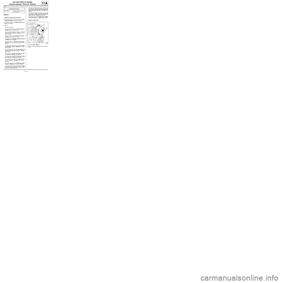
aPosition the (Mot. 1490-01) (1) .
aRemove the camshaft dephaser pulley blanking cov-
er (2) . Special tooling required
Mot. 1490-01For locking and adjusting the
camshaft pulle ys.
103265
Page 254 of 652
11A-137
TOP AND FRONT OF ENGINE
Camshaft dephaser: Removal - Refitting
K4M
11A
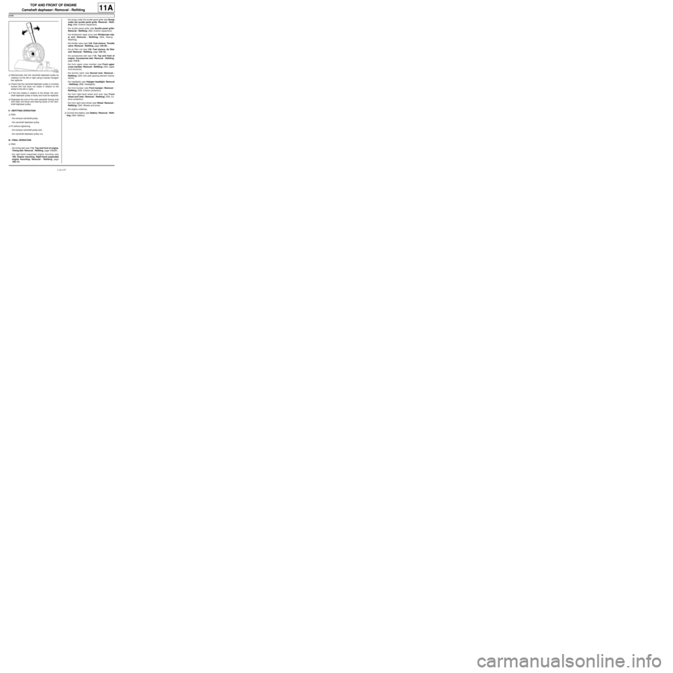
aMechanically lock the camshaft dephaser pulley by
rotating it to the left or right using a tubular hexagon
box spanner.
aCheck that the camshaft dephaser pulley is correctly
locked (the hub does not rotate in relation to the
wheel to the left or right).
aIf the hub rotates in relation to the wheel, the cam-
shaft dephaser pulley is faulty and must be replaced.
aDegrease the end of the inlet camshaft (timing end)
and clean the bores and bearing faces of the cam-
shaft dephaser pulley.
II - REFITTING OPERATION
aRefit:
-the exhaust camshaft pulley.
-the camshaft dephaser pulley.
aFit without tightening:
-the exhaust camshaft pulley bolt,
-the camshaft dephaser pulley nut.
III - FINAL OPERATION
aRefit:
-the timing belt (see 11A, Top and front of engine,
Timing belt: Removal - Refitting, page 11A-27) ,
-the right-hand suspended engine mounting (see
19D, Engine mounting, Right-hand suspended
engine mounting: Removal - Refitting, page
19D-13) ,-the scoop under the scuttle panel grille (see Scoop
under the scuttle panel grille: Removal - Refit-
ting) (56A, Exterior equipment),
-the scuttle panel grille (see Scuttle panel grille:
Removal - Refitting) (56A, Exterior equipment),
-the windscreen wiper arms (see Windscreen wip-
er arm: Removal - Refitting) (85A, Wiping -
Washing),
-the throttle valve (see 12A, Fuel mixture, Throttle
valve: Removal - Refitting, page 12A-20) ,
-the air filter unit (see 12A, Fuel mixture, Air filter
unit: Removal - Refitting, page 12A-13) ,
-the accessories belt (see 11A, Top and front of
engine, Accessories belt: Removal - Refitting,
page 11A-3) ,
-the front upper cross member (see Front upper
cross member: Removal - Refitting) (42A, Upper
front structure),
-the bonnet catch (see Bonnet lock: Removal -
Refitting) (52A, Non-side opening element mecha-
nisms),
-the headlights (see Halogen headlight: Removal
- Refitting) (80B, Headlights),
-the front bumper (see Front bumper: Removal -
Refitting) (55A, Exterior protection),
-the front right-hand wheel arch liner (see Front
wheel arch liner: Removal - Refitting) (55A, Ex-
terior protection),
-the front right-hand wheel (see Wheel: Removal -
Refitting) (35A, Wheels and tyres),
-the engine undertray.
aConnect the battery (see Battery: Removal - Refit-
ting) (80A, Battery).
111340
Page 258 of 652
11A-141
TOP AND FRONT OF ENGINE
Camshaft seal, timing end: Removal - Refitting
K4M
11A
REMOVAL
I - REMOVAL PREPARATION OPERATION
aPosition the vehicle on a two-post lift (see Vehicle:
Towing and lifting) (02A, Lifting equipment).
aDisconnect the battery (see Battery: Removal - Re-
fitting) (80A, Battery).
aRemove:
-the engine undertray,
-the front right-hand wheel (see Wheel: Removal -
Refitting) (35A, Wheels and tyres),
-the front right-hand wheel arch liner (see Front
wheel arch liner: Removal - Refitting) (55A, Ex-
terior protection),
-the front bumper (see Front bumper: Removal -
Refitting) (55A, Exterior protection),
-the headlights (see Halogen headlight: Removal
- Refitting) (80B, Headlights),
-the bonnet catch (see Bonnet lock: Removal -
Refitting) (52A, Non-side opening element mecha-
nisms),
-the front upper cross member (see Front upper
cross member: Removal - Refitting) (42A, Upper
front structure),
-the accessories belt (see 11A, Top and front of
engine, Accessories belt: Removal - Refitting,
page 11A-3) ,
-the air filter unit (see 12A, Fuel mixture, Air filter
unit: Removal - Refitting, page 12A-13) ,
-the throttle valve (see 12A, Fuel mixture, Throttle
valve: Removal - Refitting, page 12A-20) ,
-the windscreen wiper arms (see Windscreen wip-
er arm: Removal - Refitting) (85A, Wiping -
Washing),
-the scuttle panel grille (see Scuttle panel grille:
Removal - Refitting) (56A, Exterior equipment),
-the scoop under the scuttle panel grille (see Scoop
under the scuttle panel grille: Removal - Refit-
ting) (56A, Exterior equipment),-the right-hand suspended engine mounting (see
19D, Engine mounting, Right-hand suspended
engine mounting: Removal - Refitting, page
19D-13) ,
-the crankshaft accessories pulley (see 11A, Top
and front of engine, Crankshaft accessories
pulley: Removal - Refitting, page 11A-20) ,
-the timing belt (see 11A, Top and front of engine,
Timing belt: Removal - Refitting, page 11A-27) ,
-the camshaft dephaser (see 11A, Top and front of
engine, Camshaft dephaser: Removal - Refit-
ting, page 11A-135) .
II - REMOVAL OPERATION
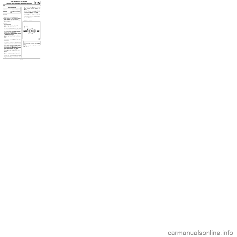
a
aCompletely unscrew the nut (1) and the bolt (Mot.
1577) of the (2) . Special tooling required
Mot. 1577Lip seal e xtractor (shaft diam-
eter 28 mm to 42 mm).
Mot. 1632Tool for fitting camshaft PTFE
seal
105257
Note:
The camshaft seal is removed using the (Mot.
1577).