Valve RENAULT TWINGO 2009 2.G Engine And Peripherals User Guide
[x] Cancel search | Manufacturer: RENAULT, Model Year: 2009, Model line: TWINGO, Model: RENAULT TWINGO 2009 2.GPages: 652
Page 104 of 652
10A-98
ENGINE AND CYLINDER BLOCK ASSEMBLY
Engine - gearbox assembly: Removal - Refitting
K4M
10A
aDisconnect:
-the fuel vapour absorber bleed solenoid valve pipe
(12) ,
-the fuel vapour absorber bleed solenoid valve con-
nector (13) .aUnclip the fuel supply pipe at (14) .
aDisconnect the fuel supply pipe (15) .
131766131767
WARNING
To prevent impur ities from entering the circuit,
place protective plugs on all fuel circuit compo-
nents exposed to the open air.
Page 109 of 652
10A-103
ENGINE AND CYLINDER BLOCK ASSEMBLY
Engine - gearbox assembly: Removal - Refitting
K4M
10A
-the rubber pad mounting from the suspended en-
gine mounting on the gearbox.
aRemove the right-hand suspended engine mounting
(see 19D, Engine mounting, Right-hand sus-
pended engine mounting: Removal - Refitting,
page 19D-13) .
aLift the vehicle to remove the "engine and gearbox"
assembly.
REFITTING
I - REFITTING PREPARATION OPERATION
aFor standard engine replacement (see Standard re-
placement) (Technical Note 6023A, 10A, Engine
and peripherals).
II - REFITTING OPERATION
aPosition the "engine and gearbox" assembly in the
body.
aRefit the right-hand suspended engine mounting
(see 19D, Engine mounting, Right-hand sus-
pended engine mounting: Removal - Refitting,
page 19D-13) .
aRefit the rubber pad mounting from the suspended
engine mounting on the gearbox.
aTorque tighten the rubber pad mounting bolts for
the suspended engine mounting on the gearbox
(21 N.m).
aRefit the suspended engine mounting rubber pad.
aTorque tighten:
-the bolts of the suspended mounting rubber
pad (62 N.m),
-the suspended engine mounting shaft nut (62
N.m).
III - FINAL OPERATION
aRemove the.
aRemove the blanking plugs.
aConnect:
-the union of the brake servo vacuum pipe,
-the « compressor - condenser » connecting pipe,-the « compressor - intermediate pipe » connecting
pipe,
-the pressure sensor connector,
aConnect the hose on the coolant pump inlet pipe.
aFit the hose clip on the coolant pump inlet pipe using
the (Mot. 1448).
aRefit the earth nuts.
aClip:
-the relay plates on the engine compartment con-
nection unit,
-the fuse holders.
aConnect the fuses.
aRefit the engine compartment connection unit on the
body.
aConnect the connector to the engine compartment
connection unit.
aRefit the engine compartment connection unit cover.
aClip:
-the wiring on the engine cooling fan assembly,
-the cooling radiator top and bottom hoses on the
engine cooling fan assembly.
aConnect:
-the engine cooling fan assembly resistor connec-
tor,
-the engine cooling fan assembly connector.
aRemove the blanking plug from the fuel supply pipe
opening and the injector rail fuel opening.
aReconnect the fuel supply pipe.
aClip the fuel supply pipe in place.
aConnect:
-the fuel vapour absorber bleed solenoid valve con-
nector,
-the fuel vapour absorber bleed solenoid valve pipe.
aFit the gearbox control cables.
aClip the manual gearbox control cables onto:
-the gear selectors,
-the cable sleeve stops.
aRemove the blanking plug from the hydraulic clutch
control pipe opening and the opening of the clutch
thrust bearing.
aConnect the hydraulic clutch control pipe.
aClip the hydraulic clutch control pipe on the gearbox. Note:
Check no component obstructs the movement of
the body around the engine - gearbox assembly.
Page 111 of 652
10A-105
ENGINE AND CYLINDER BLOCK ASSEMBLY
Valves: Adjustment
C44, and K9K
10A
aParts always to be replaced:
-rocker cover gasket
aRemove the rocker cover (see 11A, Top and front
of engine, Rocker cover: Removal - Refitting,
page 11A-66) .
aTo adjust the valves (see Technical Note 6006A,
Diesel Engine - High-Pressure Common Rail - 4-
cylinder cast iron, 10A, Engine and peripherals,
Rebuilding the cylinder head).
Page 112 of 652
10A-106
ENGINE AND CYLINDER BLOCK ASSEMBLY
Valves: Adjustment
D4F or D7F
10A
I - PREPARATION STAGE FOR ADJUSTING THE
VALVE CLEARANCES
aPosition the vehicle on a two-post lift ( (see Vehicle:
Towing and lifting) ).
aDisconnect the battery ( (see Battery: Removal -
Refitting) ).
aRemove:
-the front right-hand wheel, (see Front wheel arch
liner: Removal - Refitting)
-the front right-hand wheel arch liner (see MR 412
Bodywork, 55A, Exterior protection, Wheel arch
liner: Removal - Refitting),
-the air filter unit (see 12A, Fuel mixture, Air filter
unit: Removal - Refitting, page 12A-13) ,
-the inlet manifold (see 12A, Fuel mixture, Inlet
distributor: Removal - Refitting, page 12A-29) ,
-the rocker cover (see 11A, Top and front of en-
gine, Rocker cover: Removal - Refitting, page
11A-66) .
II - ADJUSTING THE VALVE CLEARANCES
aAdjust the valve clearances (see Technical Note
6004A, Petrol engine - 4 cylinder - D4, 10A, Tim-
ing-Cylinder head: Refitting).
aAdjust the valve clearances (see MR Components,
MR - Mot - D - (E), 4 cylinder cast-iron engine
(petrol), 10 Engine and peripherals, Engine re-
pair).
III - FINAL OPERATION
aRefit:
-the rocker cover (see 11A, Top and front of en-
gine, Rocker cover: Removal - Refitting, page
11A-66) ,
-the inlet manifold (see 12A, Fuel mixture, Inlet
distributor: Removal - Refitting, page 12A-29) ,
-the air filter unit (see 12A, Fuel mixture, Air filter
unit: Removal - Refitting, page 12A-13) ,-the front right-hand wheel arch liner (see MR 412
Bodywork, 55A, Exterior protection, Wheel arch
liner: Removal - Refitting),
-the front right-hand wheel ( (see Wheel: Removal
- Refitting) ).
aConnect the battery ( (see Battery: Removal - Re-
fitting) ).
D4F
D7F
Page 118 of 652
11A-1
TOP AND FRONT OF ENGINE
Pressure at end of compression: Check
K4M
11A
CHECK
I - PREPARATION OPERATION FOR CHECK
aRemove:
-the coils (see 17A, Ignition, Coils: Removal - Re-
fitting, page 17A-1) ,
-the spark plugs (see 17A, Ignition, Plugs: Re-
moval - Refitting, page 17A-12) .
aDisconnect the injector wiring connector (1) .aConnect a petrol compression gauge (2) .
aPut the vehicle under the starting conditions by posi-
tioning the gear lever in neutral.
II - TEST OPERATION
aActivate the starter until the needle of the petrol
compression gauge stabilises.
aMeasure the cylinder compressions, cylinder by cyl-
inder.
aFully depress the accelerator pedal in order to open
the throttle valve during the compression measure-
ments.
III - FINAL OPERATION
aDisconnect the petrol compression gauge.
aConnect the injector wiring connector.
aRefit:
-the spark plugs (see 17A, Ignition, Plugs: Re-
moval - Refitting, page 17A-12) ,
-the coils (see 17A, Ignition, Coils: Removal - Re-
fitting, page 17A-1) . Equipment required
petrol compression gauge
132371
132338
Note:
It is necessar y to wait for at least 10 seconds
before starting the engine each time (the starter
will not run due to its ther mal protection).
Page 119 of 652
11A-2
TOP AND FRONT OF ENGINE
Pressure at end of compression: Check
D4F
11A
CHECK
I - PREPARATION OPERATION FOR CHECK
aRemove the plugs (see 17A, Ignition, Plugs: Re-
moval - Refitting, page 17A-12) .
aConnect a petrol compression gauge (1) .
aRun command with Diagnostic tool :
-RZ009: VEHICLE FUNCTION PROGRAMMING,
-VP036: FUEL SUPPLY INHIBITION.
aPut the vehicle under the starting conditions by posi-
tioning the gear lever in neutral.II - TEST OPERATION
aActivate the starter until the needle of the petrol
compression gauge stabilises.
aMeasure the cylinder compressions, cylinder by cyl-
inder.
aFully depress the accelerator pedal in order to open
the throttle valve during the compression measure-
ments.
III - FINAL OPERATION
aDisconnect the petrol compression gauge.
aRefit the plugs (see 17A, Ignition, Plugs: Removal
- Refitting, page 17A-12) .
aRun command VP037: "STOP INHIBIT FUEL SUP-
PLY" using the Diagnostic tool.
aStart the engine. Equipment required
petrol compression gauge
Diagnostic tool
Note:
Use a petrol compression gauge compatible with
the special tools.
The petrol compression gauge must be equipped
with a universal end piece (rubber), or a gaz 1/4
thread bolt.
132699
Note:
It is necessar y to wait for at least 10 seconds
before starting the engine each time (the starter
will not run due to its ther mal protection).
Note:
If the engine does not start, run command
VP037: STOP FUEL SUPPLY INHIBITION using
the Diagnostic tool or switch off the ignition and
wait 1 min before starting the engine again.
Page 170 of 652
11A-53
TOP AND FRONT OF ENGINE
Timing belt: Removal - Refitting
K4M
11A
REMOVAL
I - REMOVAL PREPARATION OPERATION
aPosition the vehicle on a two-post lift (see Vehicle:
Towing and lifting) (02A, Lifting equipment).
aDisconnect the battery (see Battery: Removal - Re-
fitting) (80A, Battery).
aRemove:
-the engine undertray,
-the front right-hand wheel (see Wheel: Removal -
Refitting) (35A, Wheels and tyres),
-the front right-hand wheel arch liner (see Front
wheel arch liner: Removal - Refitting) (55A, Ex-
terior protection),
-the front bumper (see Front bumper: Removal -
Refitting) (55A, Exterior protection),
-the headlights (see Halogen headlight: Removal
- Refitting) (80B, Headlights),
-the bonnet catch (see Bonnet lock: Removal -
Refitting) (52A, Non-side opening element mecha-
nisms),
-the front upper cross member (see Front upper
cross member: Removal - Refitting) (42A, Upper
front structure),
-the accessories belt (see 11A, Top and front of
engine, Accessories belt: Removal - Refitting,
page 11A-3) ,
-the air filter unit (see 12A, Fuel mixture, Air filter
unit: Removal - Refitting, page 12A-13) ,
-the throttle valve (see 12A, Fuel mixture, Throttle
valve: Removal - Refitting, page 12A-20) ,
-the windscreen wiper arms (see Windscreen wip-
er arm: Removal - Refitting) (85A, Wiping -
Washing),
-the scuttle panel grille (see Scuttle panel grille:
Removal - Refitting) (56A, Exterior equipment), Special tooling required
Mot. 1489TDC locating pin.
Mot. 1368Tool for tightening eccentric
tensioning roller bolt. 8 mm
Torx wrench and 12.7 mm
square.
Mot. 1496Camshaft timing tool.
Mot. 1750Additional tool to suppor t the
camshaft adjusting tool, Mot.
1496.
Mot. 1490-01For locking and adjusting the
camshaft pulle ys.
Mot. 1487Tool for refitting camshaft cov-
ers (57 mm diameter).
Mot. 1488Tool for refitting camshaft cov-
ers (43 mm diameter).
Equipment required
indelible pencil
Tightening torquesm
fixed roller bolt50 N.m
lower timing cover bolts12 N.m
exhaust camshaft pul-
ley nut30 N.m + 84˚
camshaft dephaser pul-
ley bolt100 N.m
timing tension wheel nut27 N.m
TDC setting pin plug20 N.m
upper timing cover bolts41 N.m
upper timing cover nuts41 N.m
rear suspended engine
reinforcement bolt105 N.m
rear suspended engine
mounting bolt on the
rear suspended engine
mounting suppor t105 N.m
rear suspended engine
mounting bolt on the
subframe105 N.m Tightening torquesm
Page 181 of 652
11A-64
TOP AND FRONT OF ENGINE
Timing belt: Removal - Refitting
K4M
11A
aRefit the lower timing cover flap, checking that the
locating pin (34) fits properly in the notch (35) .
III - FINAL OPERATION
aRefit:
-a new inlet camshaft plug using the (Mot. 1487),
-a new exhaust camshaft plug using the (Mot.
1488),
-the lifting eye.
aClip the wiring onto the lifting eye.aPlace a drop of SILICONE ADHESIVE SEALANT
(see Vehicle: Parts and consumables for the re-
pair) (04B, Consumables - Products) on the thread
of the TDC setting pin plug.
aTorque tighten the TDC setting pin plug (20 N.m).
aRefit the upper timing cover.
aTorque tighten:
-the upper timing cover bolts (41 N.m),
-the upper timing cover nuts (41 N.m).
aPosition the wiring of the upstream oxygen sensor.
aAttach the upstream oxygen sensor wiring.
aConnect the upstream oxygen sensor connector.
aRefit:
-the right-hand suspended engine mounting (see
19D, Engine mounting, Right-hand suspended
engine mounting: Removal - Refitting, page
19D-13) ,
-the rear suspended engine mounting.
aTorque tighten:
-the rear suspended engine reinforcement bolt
(105 N.m),
-the rear suspended engine mounting bolt on
the rear suspended engine mounting support
(105 N.m),
-the rear suspended engine mounting bolt on
the subframe (105 N.m).
aRefit:
-the scoop under the scuttle panel grille (see Scoop
under the scuttle panel grille: Removal - Refit-
ting) (56A, Exterior equipment),
-the scuttle panel grille (see Scuttle panel grille:
Removal - Refitting) (56A, Exterior equipment),
-the windscreen wiper arms (see Windscreen wip-
er arm: Removal - Refitting) (85A, Wiping -
Washing),
-the throttle valve (see 12A, Fuel mixture, Throttle
valve: Removal - Refitting, page 12A-20) ,
-the air filter unit (see 12A, Fuel mixture, Air filter
unit: Removal - Refitting, page 12A-13) ,
-the accessories belt (see 11A, Top and front of
engine, Accessories belt: Removal - Refitting,
page 11A-3) ,
-the front upper cross member (see Front upper
cross member: Removal - Refitting) (42A, Upper
front structure),
109052
14890
Page 189 of 652
11A-72
TOP AND FRONT OF ENGINE
Rocker cover: Removal - Refitting
D4F, and 780 or 782 or 784
11A
a
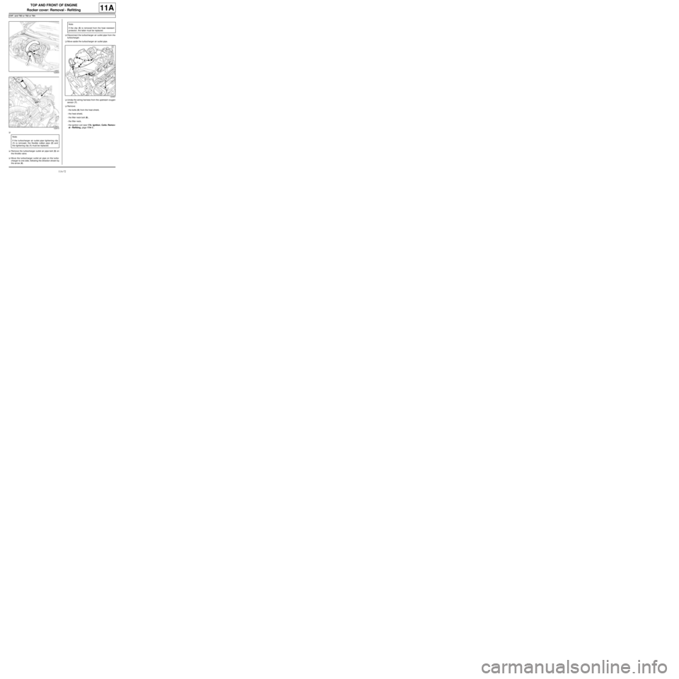
aRemove the turbocharger outlet air pipe bolt (3) on
the throttle valve.
aMove the turbocharger outlet air pipe on the turbo-
charger to one side, following the direction shown by
the arrow (4) .aDisconnect the turbocharger air outlet pipe from the
turbocharger.
aMove aside the turbocharger air outlet pipe.
aUnclip the wiring harness from the upstream oxygen
sensor (7) .
aRemove:
-the bolts (6) from the heat shield,
-the heat shield,
-the filler neck bolt (8) ,
-the filler neck,
-the ignition coil (see 17A, Ignition, Coils: Remov-
al - Refitting, page 17A-1) .
122834
122673
Note:
If the turbocharger air outlet pipe tightening clip
(1) is removed, the flexible rubber pipe (2) and
the tightening clip (1) must be replaced.
Note:
If the clip (5) is removed from the heat resistant
protector, the latter must be replaced.
120957
Page 192 of 652
11A-75
TOP AND FRONT OF ENGINE
Rocker cover: Removal - Refitting
D4F, and 780 or 782 or 784
11A
aClip the upstream oxygen sensor wiring harness into
place.
aPosition the turbocharger air outlet pipe.
aPush the turbocharger outlet air pipe clip, following
the direction shown by the arrow (10) .
aConnect the turbocharger air outlet pipe onto the tur-
bocharger.
aRefit:
-the turbocharger outlet air pipe bolt on the throttle
valve,
-the air filter unit support,
-the air filter box mounting bolt,
-the air filter unit (see 12A, Fuel mixture, Air filter
unit: Removal - Refitting, page 12A-13) .
aConnect the battery (see Battery: Removal - Refit-
ting) (80A, Battery).
122666