warning RENAULT TWINGO 2009 2.G Engine And Peripherals Workshop Manual
[x] Cancel search | Manufacturer: RENAULT, Model Year: 2009, Model line: TWINGO, Model: RENAULT TWINGO 2009 2.GPages: 652
Page 404 of 652
13B-43
DIESEL INJECTION
Injector rail: Removal - Refitting
K9K
13B
REMOVAL
I - REMOVAL PREPARATION OPERATION
aPosition the vehicle on a two-post lift (see Vehicle:
Towing and lifting) (02A, Lifting equipment)
aRemove the front engine cover.
aDisconnect the battery (see Battery: Removal - Re-
fitting) (80A, Battery).
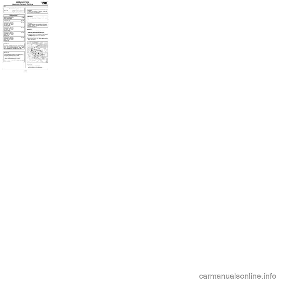
aDisconnect:
-the heater plug connectors (1) ,
-the connectors (2) from the injectors. Special tooling required
Mot. 1746Offset wrench for tightening
High Pressure pump pipes.
Tightening torquesm
studs of the injection rail
on the cylinder head8 Nm
injector rail nuts28 Nm
unions for the high pres-
sure pipes between the
rail and the yellow-
coloured injector24 Nm
unions for the high pres-
sure pipes between the
rail and the silver-
coloured injector28 Nm
unions for the high pres-
sure pipes between the
pump and the yellow-
coloured r ail24 Nm
unions for the high pres-
sure pipes between the
pump and the silver-
coloured r ail28 Nm
IMPORTANT
Consult the safety and cleanliness advice and oper-
ation recommendations before carrying out any
repair (see 13B, Diesel injection, Diesel injec-
tion: Precautions for the repair, page 13B-1) .
IMPORTANT
Use the diagnostic tool before any operation is car-
ried out on the injection circuit to check:
-that the rail is not under pressure,
-that the fuel temperature is not too high.
Working on the circuit with the engine running is
strictly forbidden.
WARNING
To avoid any corrosion or damage, protect the
areas on which fuel is likely to run.
IMPORTANT
Wear leaktight gloves (nitrile type) for this opera-
tion.
WARNING
To prevent impurities from entering the circuit, place
protective plugs on all fuel circuit components
exposed to the open air.
127895
Page 406 of 652
13B-45
DIESEL INJECTION
Injector rail: Removal - Refitting
K9K
13B
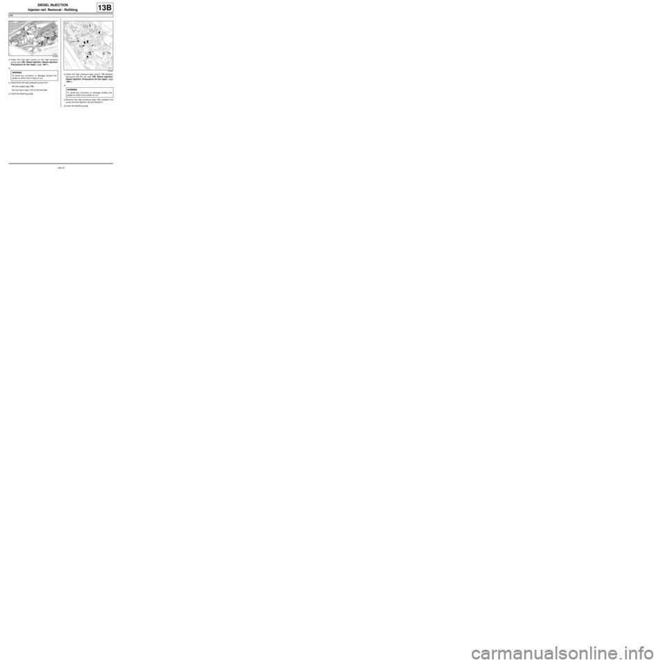
aClean the fuel pipe unions on the high pressure
pump (see 13B, Diesel injection, Diesel injection:
Precautions for the repair, page 13B-1) .
a
aDisconnect the high pressure pump from:
-the fuel supply pipe (10) ,
-the fuel return pipe (11) to the fuel filter.
aInsert the blanking plugs.aClean the high pressure pipe unions (12) between
the pump and the rail (see 13B, Diesel injection,
Diesel injection: Precautions for the repair, page
13B-1) .
a
aRemove the high pressure pipe (12) between the
pump and the injection rail and discard it.
aInsert the blanking plugs.
121423
WARNING
To avoid any corrosion or damage, protect the
areas on which fuel is likely to run.127901
WARNING
To avoid any corrosion or damage, protect the
areas on which fuel is likely to r un.
Page 407 of 652
13B-46
DIESEL INJECTION
Injector rail: Removal - Refitting
K9K
13B
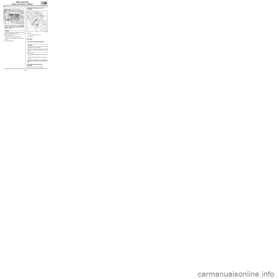
aClean the high pressure pipe unions (13) between
the injection rail and the injectors (see 13B, Diesel
injection, Diesel injection: Precautions for the
repair, page 13B-1)
aRemove then dispose of:
-the clips between the high pressure pipes,
-the high pressure pipes between the rail and the in-
jectors.
aInsert the blanking plugs.II - OPERATION FOR REMOVAL OF PART
CONCERNED
aRemove:
-the nuts (14) from the injector rail,
-the injector rail.
REFITTING
I - REFITTING PREPARATION OPERATION
a
aAlways replace:
-the high pressure pipe between the pump and the
rail,
-the high pressure pipes between the rail and the in-
jector
aIn the event of replacement, torque tighten the
studs of the injection rail on the cylinder head (8
Nm ).
II - REFITTING OPERATION FOR PART
CONCERNED
aTake the injector rail out of its packaging.
121418
WARNING
To avoid any corrosion or damage, protect the
areas on which fuel is likely to run.
127901
WARNING
Do not remove the blanking plugs from each
component until the last moment.
Also, do not remove the components from their
packaging until they are to be fitted to the vehi-
cle.
Page 408 of 652
13B-47
DIESEL INJECTION
Injector rail: Removal - Refitting
K9K
13B
aRemove the blanking plugs.
aFit the injector rail.
aFit the injector rail nuts without tightening them.
III - FINAL OPERATION.
a
aRemove the blanking plugs from the high pressure
pump and the injection rail and discard them.
aFit the high pressure pipe between the high pressure
pump and the injection rail.
aTighten the high pressure pipe unions between the
pump and the rail until contact is made.
aRemove the blanking plugs on the injection rail and
the diesel fuel injectors then discard them.
aFit the new high-pressure pipes between the rail and
the injectors.
aTighten until contact the unions of the high pressure
pipes between the rail and injector.aFit and lock the new clips between the high pressure
pipes on the rail and injectors.
aTighten to torque:
-the injector rail nuts (28 Nm),
-the unions for the high pressure pipes between
the rail and the yellow-coloured injector (24
Nm) using the tool (Mot. 1746),
-the unions for the high pressure pipes between
the rail and the silver-coloured injector (28 Nm)
using the tool (Mot. 1746),
-the unions for the high pressure pipes between
the pump and the yellow-coloured rail (24 Nm)
using the tool (Mot. 1746),
-the unions for the high pressure pipes between
the pump and the silver-coloured rail (28 Nm)
using the tool (Mot. 1746),
aConnect to the high pressure pump:
-the fuel return pipe to the fuel filter,
-the fuel supply pipe.
aRefit the neck on the injection rail.
aRemove the protection fitted on the inlet opening of
the oil level dipstick on the cylinder block.
aRefit:
-the dipstick guide,
-the oil level dipstick nut,
-the oil level dipstick.
aConnect the injector rail pressure sensor connector.
aPosition the wiring harness in its channel.
aFasten the electrical wiring to the channel.
aConnect:
-the diesel temperature sensor,
-the fuel flow actuator,
-the injector connectors,
-the heater plug connectors.
aPrime the fuel circuit using a manual priming pump
until the disconnected pipes are filled with fuel.
aCheck that there are no fuel leaks.
aConnect the battery (see Battery: Removal - Refit-
ting) (80A, Battery).
aCheck the high pressure circuit (see 13B, Diesel in-
jection, High pressure pipe: Check, page 13B-34)
.
aRefit the engine cover.
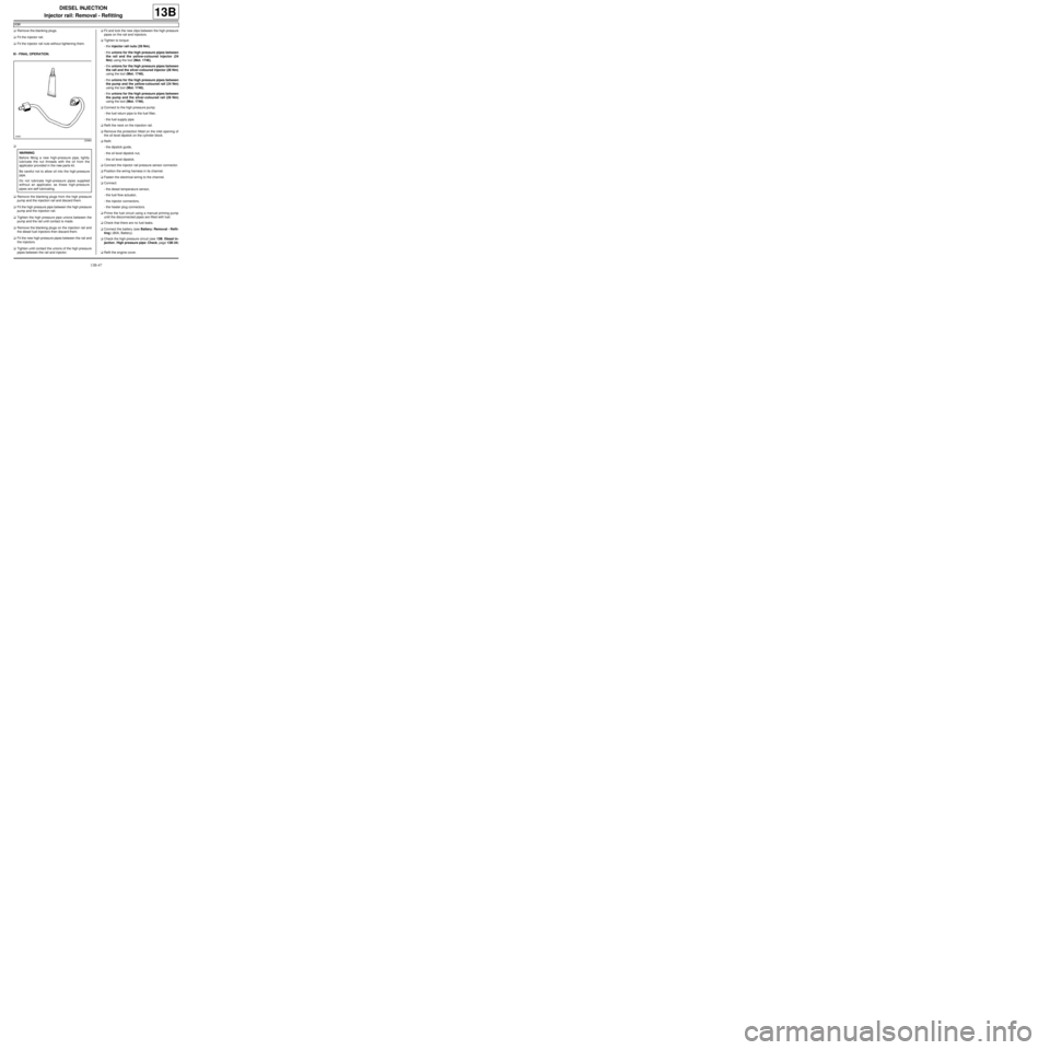
20960
WARNING
Before fitting a new high-pressure pipe, lightly
lubricate the nut threads with the oil from the
applicator provided in the new parts kit.
Be careful not to allow oil into the high-pressure
pipe.
Do not lubricate high-pressure pipes supplied
without an applicator, as these high-pressure
pipes are self-lubricating.
Page 410 of 652
13B-49
DIESEL INJECTION
Fuel temperature sensor: Removal - Refitting
C44, and K9K
13B
REMOVAL
I - REMOVAL PREPARATION OPERATION
aRemove the front engine cover.
aDisconnect the battery ( (see Battery: Removal -
Refitting) ).
aProtect the alternator from fuel outflow.
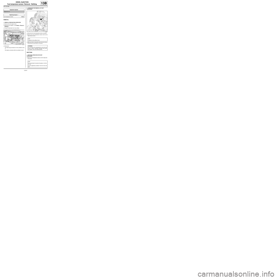
aDisconnect:
-the heater plug connectors (1) from cylinders 3 and
4,
-the injector connectors (2) from cylinders 3 and 4.II - OPERATION FOR REMOVAL OF PART
CONCERNED
aDisconnect the fuel temperature sensor connector.
aRemove the fuel temperature sensor (3) from the
high pressure pump.
aMake sure that no impurities enter the high pressure
pump when the fuel sensor is removed.
REFITTING
I - REFITTING OPERATION FOR PART
CONCERNED
aRefit the fuel temperature sensor onto the high pres-
sure pump. Equipment required
Diagnostic tool
Tightening torquesm
fuel temperature sensor15 Nm
121418
102317
Note:
Prepare for the outflow of fuel.
WARNING
Do not blast with compressed air once the fuel
circuit is open, otherwise impurities may enter
the system. Only use cleaning cloths.
Note:
Do not lubricate the seals with grease or old die-
sel fuel.
Use the applicator provided in the kit for the new
par t.
Page 412 of 652
13B-51
DIESEL INJECTION
Injector leak flow: Check
K9K
13B
PIECES ET INGREDIENTS POUR LA REPARATION
Ingrédients :
-cleaning cloths,
-set of K9K blanking plugs (DELPHI injection).
CHECK
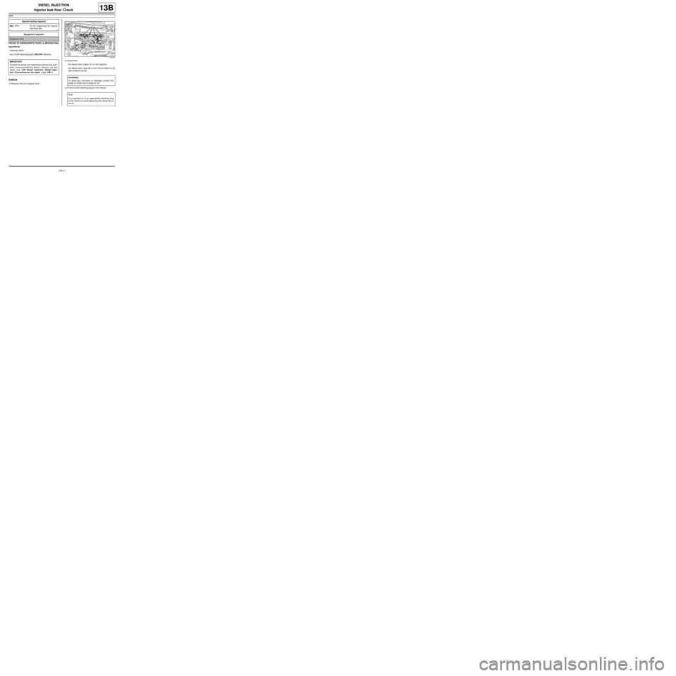
aRemove the front engine cover.aDisconnect:
-the diesel return pipes (1) on the injectors,
-the diesel return pipe (2) on the Venturi fitted on the
high pressure pump.
aFit the correct blanking plug on the Venturi. Special tooling required
Mot. 1711Kit for measuring the injector
fuel flow rate.
Equipment required
Diagnostic tool
IMPORTANT
Consult the safety and cleanliness advice and oper-
ation recommendations before carrying out any
repair (see 13B, Diesel injection, Diesel injec-
tion: Precautions for the repair, page 13B-1) .
121418
WARNING
To avoid any corrosion or damage, protect the
areas on which fuel is likely to r un.
Note:
It is essential to fi t an appropriate blanking plug
to the Venturi to avoid depriming the diesel return
circuit.
Page 422 of 652
14A-4
ANTIPOLLUTION
Fuel vapour absorber: Removal - Refitting
D4F or D7F or K4M, and TECHNICAL REG: GERMANY or TECHNICAL REG: AUSTRIA or TECHNICAL REG:
BALKANS or TECHNICAL-LEGISLATIVE BELGIUM or TECHNICAL REG: BOSNIA or TECHNICAL REG:
CYPRUS-MALTA or CZECH REP AND SLOVAKIA or TECHNICAL REG: DENMARK or TECHNICAL REG: DOM
(FRENCH OVERSEAS SUBDIVISION) or TECHNICAL REG: SPAIN or TECHNICAL REG: FINLAND or
TECHNICAL REG: FRANCE or TECHNICAL REG: GREAT BRITAIN or TECHNICAL REG: GREECE or
TECHNICAL-LEGISLATIVE HOLLAND or TECHNICAL REG: HUNGARY or TECHNICAL REG: IRELAND or
TECHNICAL REG: ICELAND or TECHNICAL REG: ISRAEL or TECHNICAL REG: ITALY or TECHNICAL REG:
JAPAN or TECHNICAL REG: NORTH or TECHNICAL REG: NORWAY or TECHNICAL REG: POLAND or
TECHNICAL REG: PORTUGAL or TECHNICAL REG: SLOVENIA or TECHNICAL REG: SWEDEN or TECHNICAL
REG: SWITZERLAND or TECHNICAL REG: TOM (FRENCH OVERSEAS TERRITORIES)
14A
REMOVAL
I - REMOVAL PREPARATION OPERATION
aPosition the vehicle on a two-post lift (see Vehicle:
Towing and lifting) (02A, Lifting equipment).
aDisconnect the battery (see Battery: Removal - Re-
fitting) (80A, Battery).
II - REMOVAL OPERATION
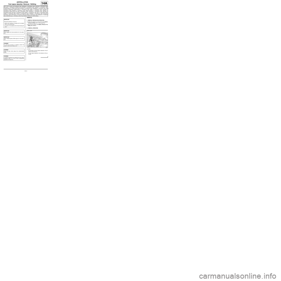
aUnclip:
-the fuel filter on the fuel vapour absorber in the di-
rection of the arrow (1) ,
-the fuel vapour absorber in the direction of the ar-
row (2) . IMPORTANT
During this oper ation, be sure to:
-refrain from smoking or bringing red hot objects
close to the working area,
-be careful of fuel splashes when disconnecting the
union.
IMPORTANT
Wear goggles with side protectors for this opera-
tion.
IMPORTANT
Wear leaktight gloves (Nitrile type) for this opera-
tion.
WARNING
To avoid any corrosion or damage, protect the
areas on which fuel is likely to run.
WARNING
Keep the pipe unions away from contaminated
areas.
WARNING
To prevent impurities from entering the circuit, place
protective plugs on all fuel circuit components
exposed to the open air.
D4F or D7F
120513
Page 424 of 652
14A-6
ANTIPOLLUTION
Fuel vapour absorber: Removal - Refitting
D4F, and SOUTH AFRICA
14A
REMOVAL
I - REMOVAL PREPARATION OPERATION
aPosition the vehicle on a two-post lift (see Vehicle:
Towing and lifting)
aDisconnect the battery (see Battery: Removal - Re-
fitting)
aRemove the rear left-hand wheel (see Wheel: Re-
moval - Refitting)
aRemove the rear left-hand wheel arch liner (see ) II - OPERATION FOR REMOVAL OF PART
CONCERNED
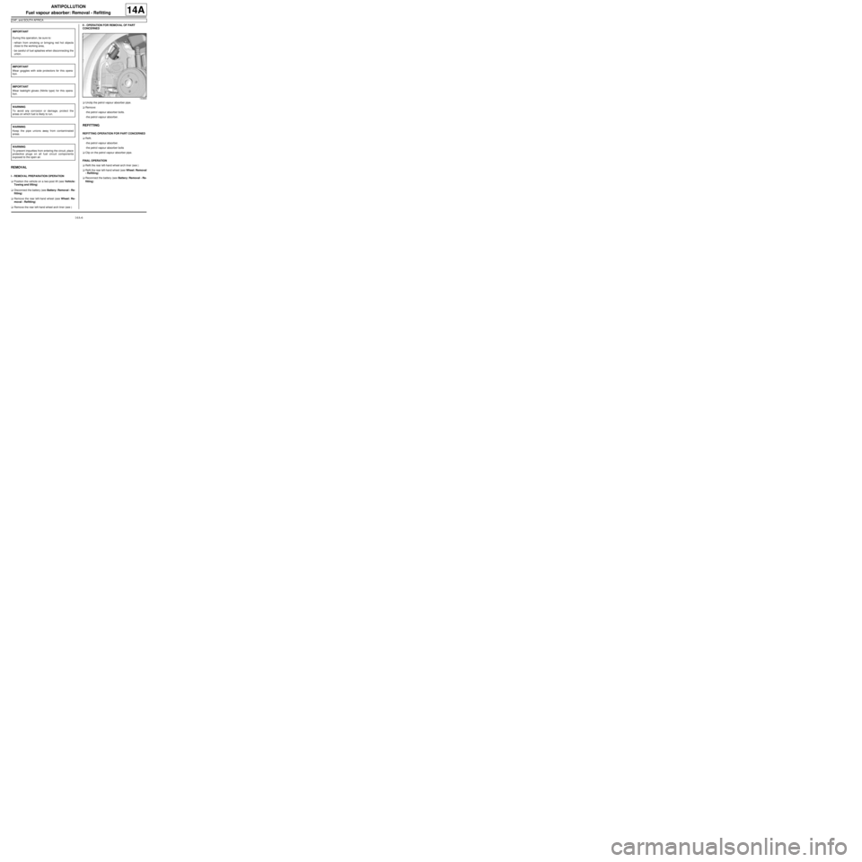
aUnclip the petrol vapour absorber pipe.
aRemove:
-the petrol vapour absorber bolts.
-the petrol vapour absorber.
REFITTING
REFITTING OPERATION FOR PART CONCERNED
aRefit.
-the petrol vapour absorber.
-the petrol vapour absorber bolts
aClip on the petrol vapour absorber pipe.
FINAL OPERATION
aRefit the rear left-hand wheel arch liner (see )
aRefit the rear left-hand wheel (see Wheel: Removal
- Refitting)
aReconnect the battery (see Battery: Removal - Re-
fitting) IMPORTANT
During this oper ation, be sure to:
-refrain from smoking or bringing red hot objects
close to the working area,
-be careful of fuel splashes when disconnecting the
union.
IMPORTANT
Wear goggles with side protectors for this opera-
tion.
IMPORTANT
Wear leaktight gloves (Nitrile type) for this opera-
tion.
WARNING
To avoid any corrosion or damage, protect the
areas on which fuel is likely to run.
WARNING
Keep the pipe unions away from contaminated
areas.
WARNING
To prevent impurities from entering the circuit, place
protective plugs on all fuel circuit components
exposed to the open air.
143884
Page 426 of 652
14A-8
ANTIPOLLUTION
Fuel vapour absorber bleed solenoid valve: Removal - Refitting
K4M
14A
REMOVAL
I - REMOVAL PREPARATION OPERATION
aDisconnect the battery (see Battery: Removal - Re-
fitting) (80A, Battery).
aRemove:
-the windscreen wiper arms (see Windscreen wip-
er arm: Removal - Refitting) (85A, Wiping -
Washing),
-the scuttle panel grille (see Scuttle panel grille:
Removal - Refitting) (56A, Exterior equipment),
-the scoop under the scuttle panel grille (see Scoop
under the scuttle panel grille: Removal - Refit-
ting) (56A, Exterior equipment).II - REMOVAL OPERATION
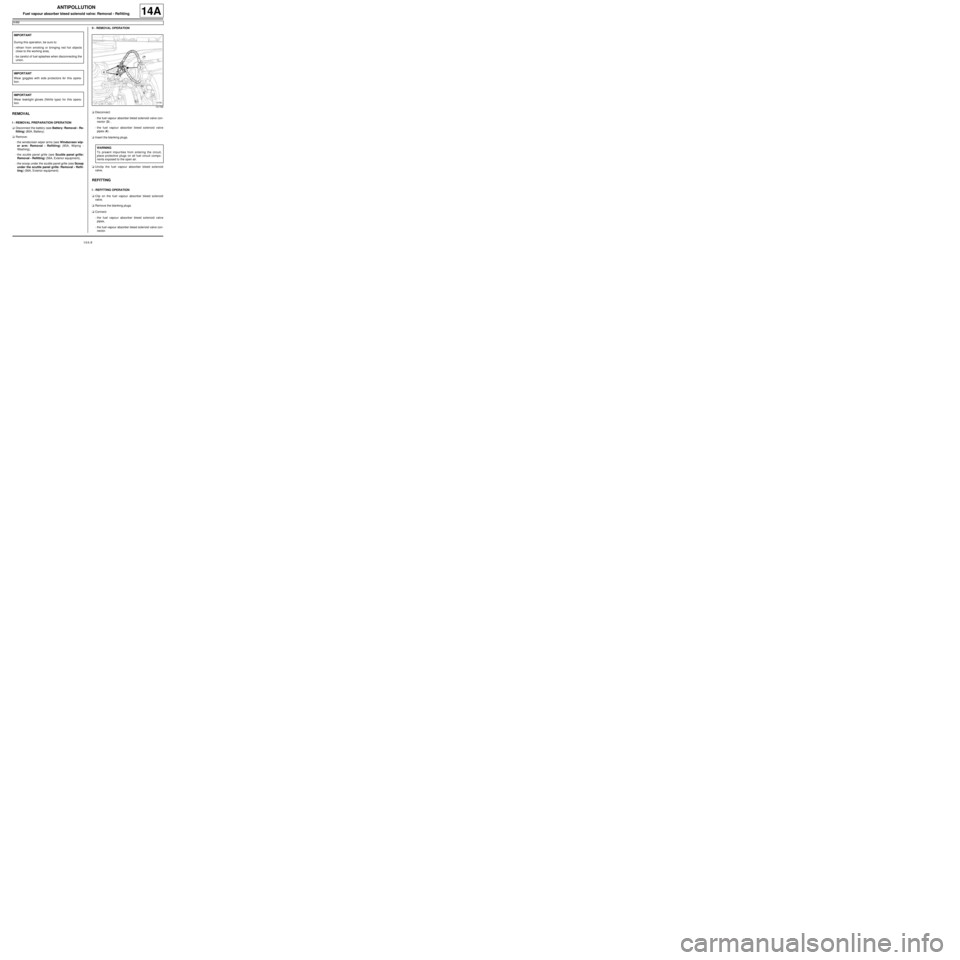
aDisconnect:
-the fuel vapour absorber bleed solenoid valve con-
nector (3) ,
-the fuel vapour absorber bleed solenoid valve
pipes (4) .
aInsert the blanking plugs.
aUnclip the fuel vapour absorber bleed solenoid
valve.
REFITTING
I - REFITTING OPERATION
aClip on the fuel vapour absorber bleed solenoid
valve.
aRemove the blanking plugs.
aConnect:
-the fuel vapour absorber bleed solenoid valve
pipes,
-the fuel vapour absorber bleed solenoid valve con-
nector. IMPORTANT
During this oper ation, be sure to:
-refrain from smoking or bringing red hot objects
close to the working area,
-be careful of fuel splashes when disconnecting the
union.
IMPORTANT
Wear goggles with side protectors for this opera-
tion.
IMPORTANT
Wear leaktight gloves (Nitrile type) for this opera-
tion.
131766
WARNING
To prevent impur ities from entering the circuit,
place protective plugs on all fuel circuit compo-
nents exposed to the open air.
Page 430 of 652
14A-12
ANTIPOLLUTION
Exhaust gas cooler: Removal - Refitting
K9K
14A
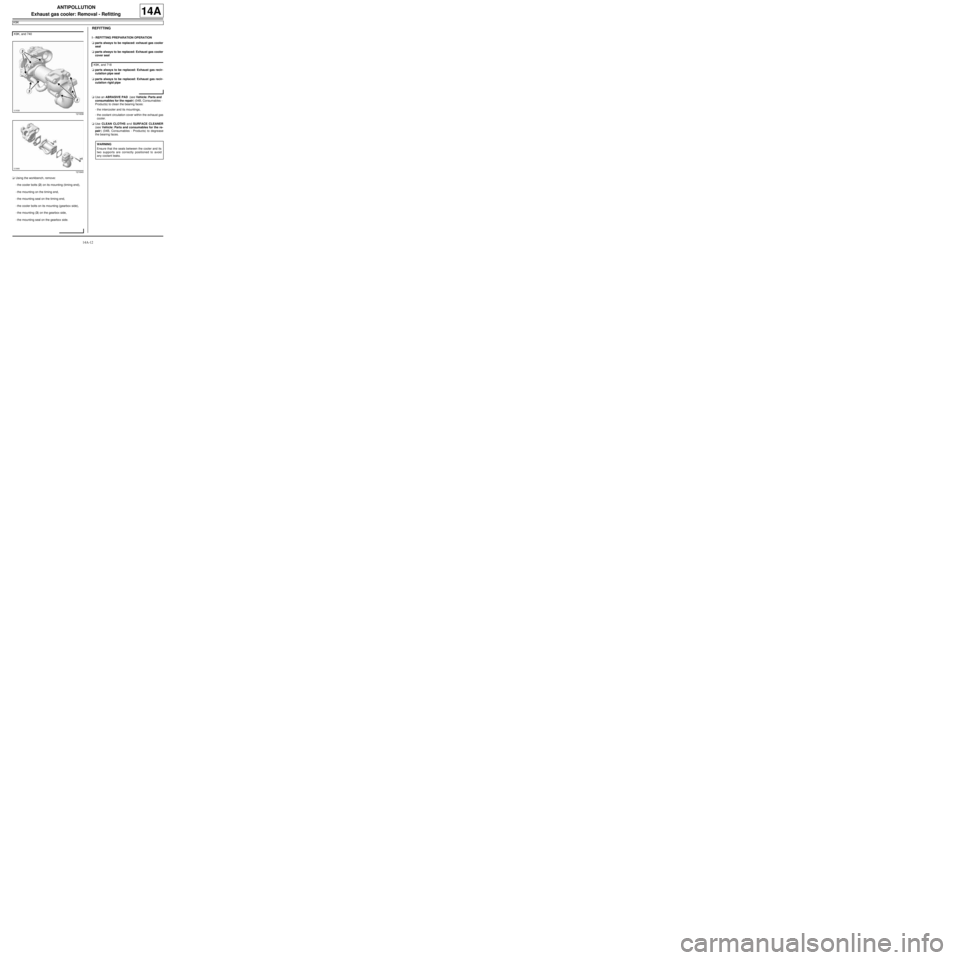
aUsing the workbench, remove:
-the cooler bolts (2) on its mounting (timing end),
-the mounting on the timing end,
-the mounting seal on the timing end,
-the cooler bolts on its mounting (gearbox side),
-the mounting (3) on the gearbox side,
-the mounting seal on the gearbox side.
REFITTING
I - REFITTING PREPARATION OPERATION
aparts always to be replaced: exhaust gas cooler
seal
aparts always to be replaced: Exhaust gas cooler
cover seal
aparts always to be replaced: Exhaust gas recir-
culation pipe seal
aparts always to be replaced: Exhaust gas recir-
culation rigid pipe
aUse an ABRASIVE PAD (see Vehicle: Parts and
consumables for the repair) (04B, Consumables -
Products) to clean the bearing faces:
-the intercooler and its mountings,
-the coolant circulation cover within the exhaust gas
cooler.
aUse CLEAN CLOTHS and SURFACE CLEANER
(see Vehicle: Parts and consumables for the re-
pair) (04B, Consumables - Products) to degrease
the bearing faces. K9K, and 740
121638
121640
K9K, and 718
WARNING
Ensure that the seals between the cooler and its
two supports are correctly positioned to avoid
any coolant leaks.