warning RENAULT TWINGO 2009 2.G Engine And Peripherals Owner's Guide
[x] Cancel search | Manufacturer: RENAULT, Model Year: 2009, Model line: TWINGO, Model: RENAULT TWINGO 2009 2.GPages: 652
Page 134 of 652
11A-17
TOP AND FRONT OF ENGINE
Accessories belt: Removal - Refitting
K4M
11A
REMOVAL
I - REMOVAL PREPARATION OPERATION
aPosition the vehicle on a two-post lift (see Vehicle:
Towing and lifting) (02A, Lifting equipment).
aDisconnect the battery (see Battery: Removal - Re-
fitting) (80A, Battery).
aRemove:
-the engine undertray,
-the front right-hand wheel (see Wheel: Removal -
Refitting) (35A, Wheels and tyres),
-the front right-hand wheel arch liner (see Front
wheel arch liner: Removal - Refitting) (55A, Ex-
terior protection),
-the front bumper (see Front bumper: Removal -
Refitting) (55A, Exterior protection),
-the headlights (see Halogen headlight: Removal
- Refitting) (80B, Headlights),
-the bonnet catch (see Bonnet lock: Removal -
Refitting) (52A, Non-side opening element mecha-
nisms),
-the front upper cross member (see Front upper
cross member: Removal - Refitting) (42A, Upper
front structure).aUnclip:
-the wiring at (1) ,
-the windscreen washer bottle filler neck at (2) ,
-the air conditioning pipe from the right-hand head-
light carrier panel.
aRemove:
-the nut (3) from the right-hand headlight carrier
panel,
-the bolts (4) from the right-hand headlight carrier
panel,
-the right-hand headlight carrier panel. Tightening torquesm
tensioning roller40 N.m
WARNING
Do not r un the engine without the accessories belt
to avoid damaging the crankshaft accessories pul-
ley.
IMPORTANT
Wear cut-resistant gloves during the operation.132339
Page 138 of 652
11A-21
TOP AND FRONT OF ENGINE
Crankshaft accessories pulley: Removal - Refitting
D4F or D7F, and AIR CONDITIONING or STANDARD HEATING
11A
aLock the flywheel by inserting a large flat-blade
screwdriver into the gearbox aperture.
aRemove:
-the accessories pulley bolt (2) ,
-the accessories pulley.
REFITTING
I - REFITTING PREPARATION OPERATION
aClean the crankshaft accessories pulley V-grooves
with a brush to prevent any deposits.aparts always to be replaced: Accessories belt,
parts always to be replaced: Accessories belt
tensioning roller,
parts always to be replaced: Accessories ten-
sioning roller bolt (to be replaced by the hexagonal
head bolt, part no. 77 03 101 075),
parts always to be replaced: Crankshaft acces-
sories pulley bolts.
aparts always to be replaced: Accessories belt,
parts always to be replaced: Crankshaft acces-
sories pulley bolts.
II - REFITTING OPERATION FOR PART
CONCERNED
aRefit the crankshaft accessories pulley using a new
bolt.
aTorque tighten the crankshaft accessories pulley
bolt (40 N.m + 75˚ ±± ± ±
6).
aRemove the large flat screwdriver from the opening
in the gearbox.
aRemove the immobilising tool (Mot. 582-01).
aRefit the flywheel protector.
III - FINAL OPERATION
aRefit:
-the accessories belt (see 11A, Top and front of
engine, Accessories belt: Removal - Refitting,
page 11A-3) , D4F, and 780 or 782
122665
WARNING
Only use brushes with plastic or non-corrosive
metal (brass) bristles.
AIR CONDITIONING
STANDARD HEATING
D4F, and 780 or 782
D4F, and 772 – D7F
Page 142 of 652
11A-25
TOP AND FRONT OF ENGINE
Crankshaft accessories pulley: Removal - Refitting
K4M
11A
REMOVAL
I - REMOVAL PREPARATION OPERATION
aPosition the vehicle on a two-post lift (see Vehicle:
Towing and lifting) (02A, Lifting equipment).
aDisconnect the battery (see Battery: Removal - Re-
fitting) (80A, Battery).
aRemove:
-the front right-hand wheel (see Wheel: Removal -
Refitting) (35A, Wheels and tyres),
-the engine undertray,
-the front right-hand wheel arch liner (see Front
wheel arch liner: Removal - Refitting) (55A, Ex-
terior protection),
-the front bumper (see Front bumper: Removal -
Refitting) (55A, Exterior protection),
-the headlights (see Halogen headlight: Removal
- Refitting) (80B, Headlights),
-the bonnet catch (see Bonnet lock: Removal -
Refitting) (52A, Non-side opening element mecha-
nisms),
-the front upper cross member (see Front upper
cross member: Removal - Refitting) (42A, Upper
front structure),
-the accessories belt (see 11A, Top and front of
engine, Accessories belt: Removal - Refitting,
page 11A-3) .II - REMOVAL OPERATION
aRemove:
-the bolt (1) from the crankshaft accessories pulley
by locking the flywheel using a screwdriver,
-the crankshaft accessories pulley.
REFITTING
I - REFITTING PREPARATION OPERATION
aparts always to be replaced: Crankshaft acces-
sories pulley bolts. Tightening torquesm
crankshaft accessories
pulley bolts120 N.m + 95˚
±± ± ±
10˚
IMPORTANT
Wear cut-resistant gloves during the operation.
WARNING
Do not r un the engine without the accessories belt
to avoid damaging the crankshaft accessories pul-
ley.
133106
14487
Page 155 of 652
11A-38
TOP AND FRONT OF ENGINE
Timing belt: Removal - Refitting
K9K
11A
REMOVAL
I - REMOVAL PREPARATION OPERATION
aPosition the vehicle on a two-post lift (see Vehicle:
Towing and lifting) (02A, Lifting equipment).
aDisconnect the battery (see Battery: Removal - Re-
fitting) (80A, Battery).aRemove:
-the engine cover,
-the windscreen wiper arms (see Windscreen wip-
er arm: Removal - Refitting) (85A, Wiping -
Washing),
-the scuttle panel grille (see Scuttle panel grille:
Removal - Refitting) (56A, Exterior equipment),
-the scoop under the scuttle panel grille (see Scoop
under the scuttle panel grille: Removal - Refit-
ting) (56A, Exterior equipment),
-the front wheels (see Wheel: Removal - Refitting)
(35A, Wheels and tyres),
-the front wheel arch liners (see Front wheel arch
liner: Removal - Refitting) (55A, Exterior protec-
tion),
-the front bumper (see Front bumper: Removal -
Refitting) (55A, Exterior protection),
-the halogen headlights (see Halogen headlight:
Removal - Refitting) (80B, Headlights),
-the front upper cross member (see Front upper
cross member: Removal - Refitting) (42A, Upper
front structure),
-the lower engine tie-bar (see 19D, Engine mount-
ing, Lower engine tie-bar: Removal - Refitting,
page 19D-18) ,
-the right-hand suspended engine mounting (see
19D, Engine mounting, Right-hand suspended
engine mounting: Removal - Refitting, page
19D-13) ,
-the camshaft position sensor (see 13B, Diesel in-
jection, Camshaft position sensor: Removal -
Refitting, page 13B-14) ,
-the accessories belt (see 11A, Top and front of
engine, Accessories belt: Removal - Refitting,
page 11A-3) ,
-the crankshaft accessories pulley (see 11A, Top
and front of engine, Crankshaft accessories
pulley: Removal - Refitting, page 11A-20) . Special tooling required
Mot. 1672Low er engine support.
Mot. 1489TDC locating pin.
Mot. 1430Set of 5 crankshaft and cam-
shaft pulley timing pins.
Tightening torquesm
tensioning roller bolt27 N.m
camshaft pulley wheel
bolts14 N.m
TDC setting pin plug25 N.m
cylinder head sus-
pended mounting bolts25 Nm
IMPORTANT
Wear protective gloves during the operation.
WARNING
The belt must be replaced with a new one if it has
been removed.
WARNING
When replacing the belt, always replace the tension
wheels and idler pulleys.
WARNING
Do not r un the engine without the accessories belt
to avoid damaging the crankshaft accessories pul-
ley.
Page 175 of 652
11A-58
TOP AND FRONT OF ENGINE
Timing belt: Removal - Refitting
K4M
11A
II - REFITTING OPERATION
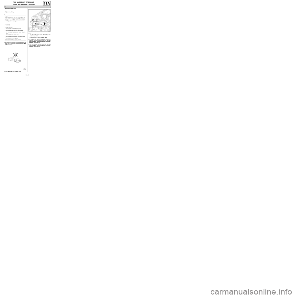
1 - Adjusting the timing
a
aSet the camshaft grooves horizontally and below the
centre line by turning the camshafts with the (Mot.
1496) if necessary.
aFit the (Mot. 1496) with the (Mot. 1750).aFit:
-the (Mot. 1496) fitted with the (Mot. 1750) on the
end of the camshaft,
-a lifting eye bolt to secure the (Mot. 1496).
aIf fitting a new camshaft dephaser, check the
dephaser locking mechanism (see 11A, Top and
front of engine, Camshaft dephaser: Removal -
Refitting, page 11A-135) .
aRefit the camshaft dephaser (see 11A, Top and
front of engine, Camshaft dephaser: Removal -
Refitting, page 11A-135) . Note:
If the stud loosens with the nut (see 11A, Top
and front of engine, Camshaft: Removal -
Refitting, page 11A-82) (Technical Note 3887A,
11A, Top and front of engine).
WARNING
Always degrease:
-the end of the crankshaft (timing end),
-the timing sprocket bore and bear ing faces,
-the crankshaft accessories pulley bearing
faces,
-the camshaft ends (timing end),
-the camshaft sprocket bores and bear ing faces.
This is to avoid timing slippage.
This slippage leads to engine damage.
111337
111336
Page 186 of 652
11A-69
TOP AND FRONT OF ENGINE
Rocker cover: Removal - Refitting
D4F, and 772
11A
REMOVAL
I - REMOVAL PREPARATION OPERATION
aDisconnect the battery (see Battery: Removal - Re-
fitting) (80A, Battery).
aRemove:
-the air filter unit (see 12A, Fuel mixture, Air filter
unit: Removal - Refitting, page 12A-13) ,
-the inlet distributor (see 12A, Fuel mixture, Inlet
distributor: Removal - Refitting, page 12A-29) ,
-the ignition coil (see 17A, Ignition, Coils: Remov-
al - Refitting, page 17A-1) .
aUnclip the rocker cover electric wiring harnesses.
II - OPERATION FOR REMOVAL OF PART
CONCERNED
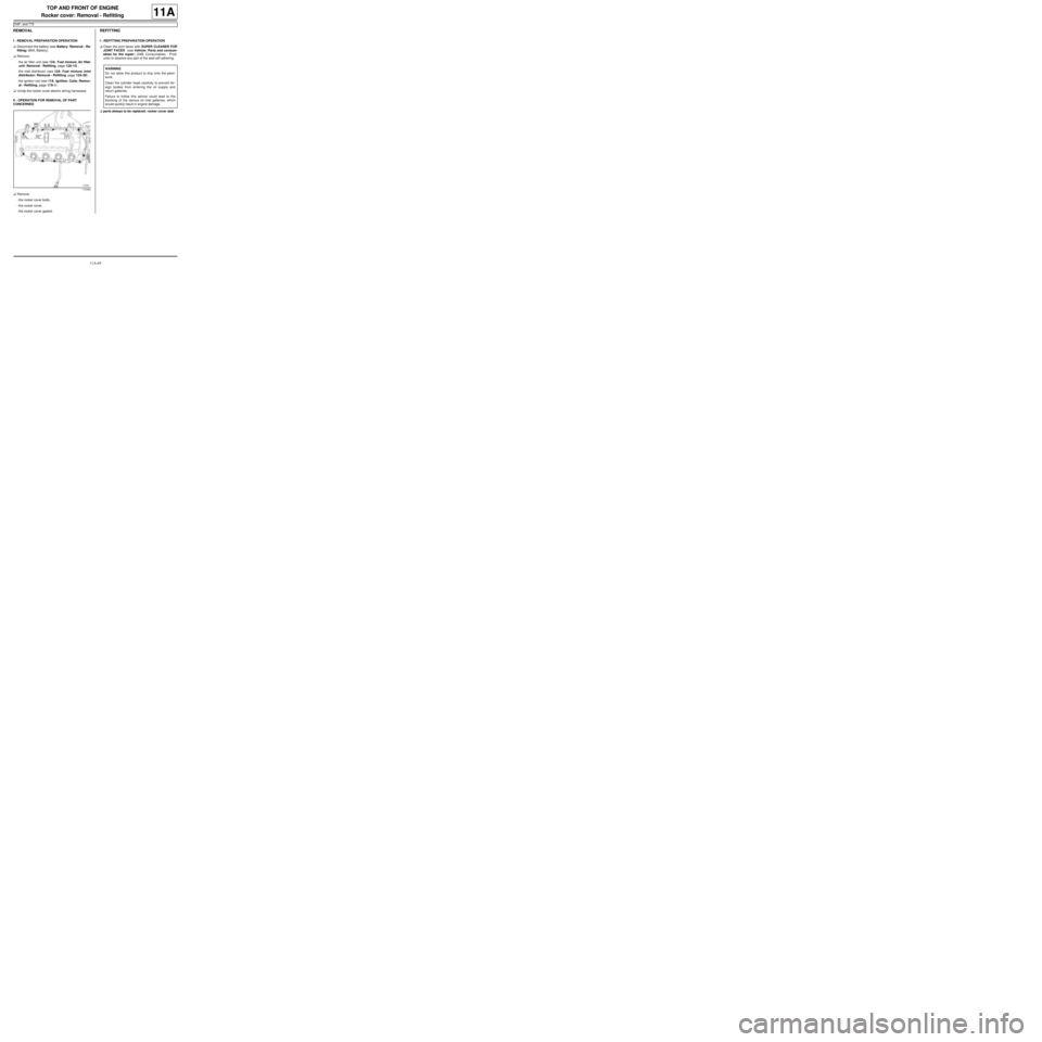
aRemove:
-the rocker cover bolts,
-the rocker cover,
-the rocker cover gasket.
REFITTING
I - REFITTING PREPARATION OPERATION
aClean the joint faces with SUPER CLEANER FOR
JOINT FACES (see Vehicle: Parts and consum-
ables for the repair) (04B, Consumables - Prod-
ucts) to dissolve any part of the seal still adhering.
aparts always to be replaced: rocker cover seal.
110422
WARNING
Do not allow this product to dr ip onto the paint-
work.
Clean the cylinder head carefully to prevent for-
eign bodies from entering the oil supply and
return galleries.
Failure to follow this advice could lead to the
blocking of the various oil inlet galleries, which
would quickly result in engine damage.
Page 190 of 652
11A-73
TOP AND FRONT OF ENGINE
Rocker cover: Removal - Refitting
D4F, and 780 or 782 or 784
11A
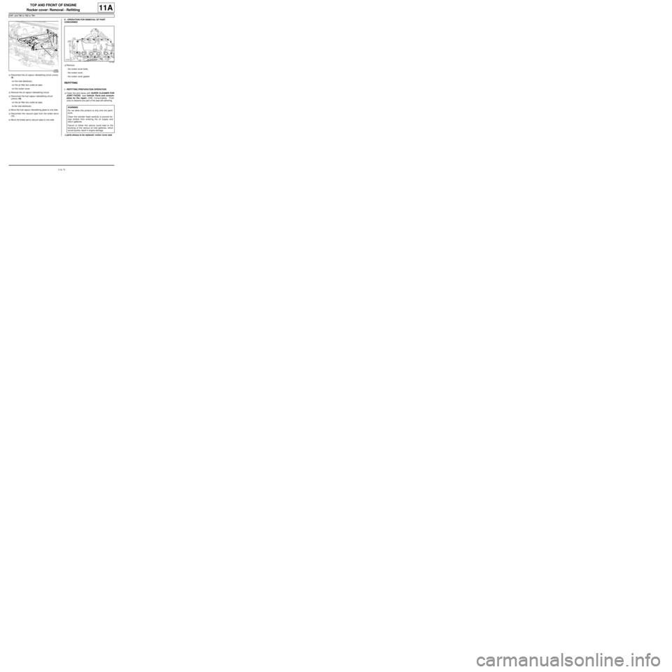
aDisconnect the oil vapour rebreathing circuit unions
(9) .
-on the inlet distributor,
-on the air filter box outlet air pipe,
-on the rocker cover.
aRemove the oil vapour rebreathing circuit.
aDisconnect the fuel vapour rebreathing circuit
unions (10) .
-on the air filter box outlet air pipe,
-to the inlet distributor.
aMove the fuel vapour rebreathing pipes to one side.
aDisconnect the vacuum pipe from the brake servo
(11) .
aMove the brake servo vacuum pipe to one side.II - OPERATION FOR REMOVAL OF PART
CONCERNED
aRemove:
-the rocker cover bolts,
-the rocker cover,
-the rocker cover gasket.
REFITTING
I - REFITTING PREPARATION OPERATION
aClean the joint faces with SUPER CLEANER FOR
JOINT FACES (see Vehicle: Parts and consum-
ables for the repair) (04B, Consumables - Prod-
ucts) to dissolve any part of the seal still adhering.
aparts always to be replaced: rocker cover seal.
122828
121026
WARNING
Do not allow this product to dr ip onto the paint-
work.
Clean the cylinder head carefully to prevent for-
eign bodies from entering the oil supply and
return galleries.
Failure to follow this advice could lead to the
blocking of the various oil inlet galleries, which
would quickly result in engine damage.
Page 191 of 652
11A-74
TOP AND FRONT OF ENGINE
Rocker cover: Removal - Refitting
D4F, and 780 or 782 or 784
11A
II - REFITTING OPERATION FOR PART
CONCERNED
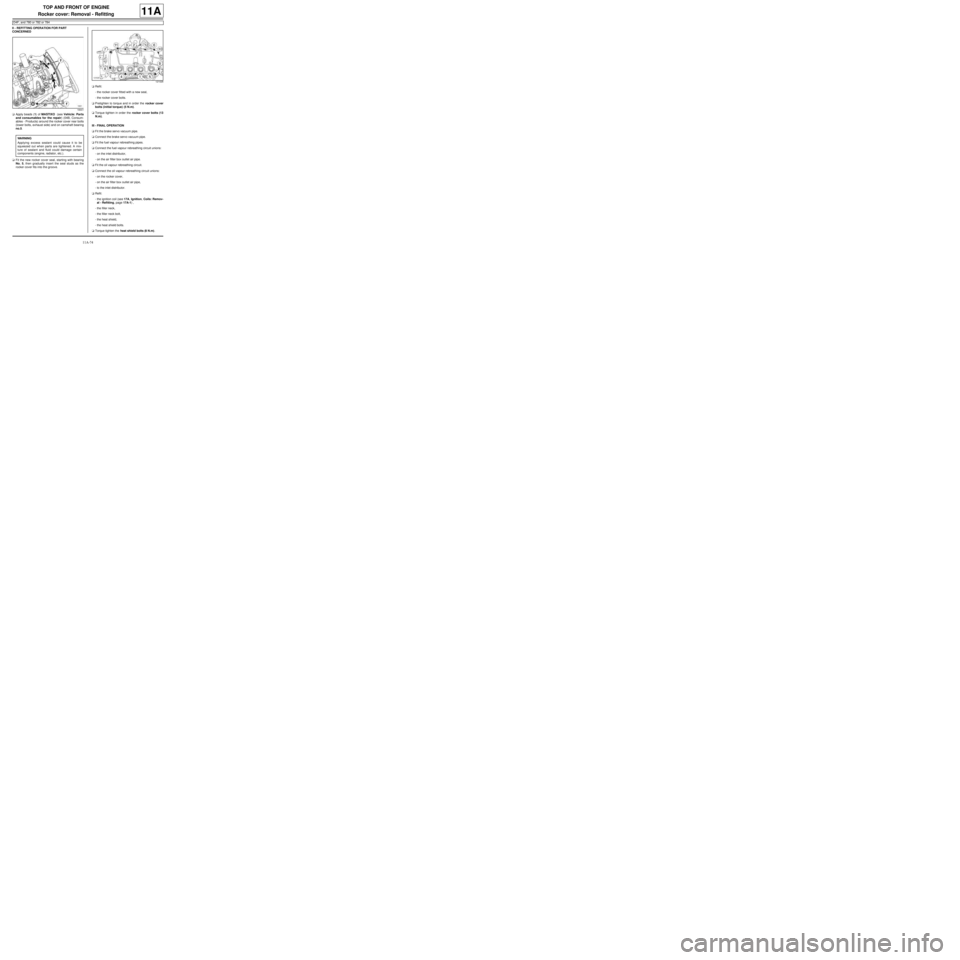
aApply beads (1) of MASTIXO (see Vehicle: Parts
and consumables for the repair) (04B, Consum-
ables - Products) around the rocker cover rear bolts
(lower bolts, exhaust side) and on camshaft bearing
no.5.
aFit the new rocker cover seal, starting with bearing
No. 5, then gradually insert the seal studs as the
rocker cover fits into the groove.aRefit:
-the rocker cover fitted with a new seal,
-the rocker cover bolts.
aPretighten to torque and in order the rocker cover
bolts (initial torque) (5 N.m).
aTorque tighten in order the rocker cover bolts (13
N.m).
III - FINAL OPERATION
aFit the brake servo vacuum pipe.
aConnect the brake servo vacuum pipe.
aFit the fuel vapour rebreathing pipes.
aConnect the fuel vapour rebreathing circuit unions:
-on the inlet distributor,
-on the air filter box outlet air pipe.
aFit the oil vapour rebreathing circuit.
aConnect the oil vapour rebreathing circuit unions:
-on the rocker cover,
-on the air filter box outlet air pipe,
-to the inlet distributor.
aRefit:
-the ignition coil (see 17A, Ignition, Coils: Remov-
al - Refitting, page 17A-1) ,
-the filler neck,
-the filler neck bolt,
-the heat shield,
-the heat shield bolts.
aTorque tighten the heat shield bolts (8 N.m).
18441
WARNING
Applying excess sealant could cause it to be
squeezed out when parts are tightened. A mix-
ture of sealant and fluid could damage certain
components (engine, radiator, etc.).
121026
Page 195 of 652
11A-78
TOP AND FRONT OF ENGINE
Rocker cover: Removal - Refitting
K4M
11A
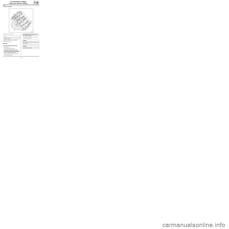
II - REMOVAL OPERATION
aRemove the rocker cover bolts.
aDetach the rocker cover using a screwdriver.
aRemove the rocker cover.
REFITTING
I - REFITTING PREPARATION OPERATION
aAlways replace:
-the camshaft position sensor seal,
-the camshaft dephaser solenoid valve seal.
aUse SUPER CLEANER FOR JOINT FACES (see
Vehicle: Parts and consumables for the repair)
(04B, Consumables - Products) to clean:
-the rocker cover joint face if it is to be re-used,
-the cylinder head joint face.aUse SURFACE CLEANER (see Vehicle: Parts
and consumables for the repair) (04B, Consuma-
bles - Products) to degrease:
-the rocker cover joint face if it is to be re-used,
-the cylinder head joint face.
14497-5
Note:
The rocker cover bolts are not the same length;
mark their positions.
WARNING
Do not scrape the joint faces of the aluminium,
any damage caused to the joint face will result in
a risk of leaks.
WARNING
The joint faces must be clean, dr y and free from
grease (avoid finger marks).
Page 196 of 652
11A-79
TOP AND FRONT OF ENGINE
Rocker cover: Removal - Refitting
K4M
11A
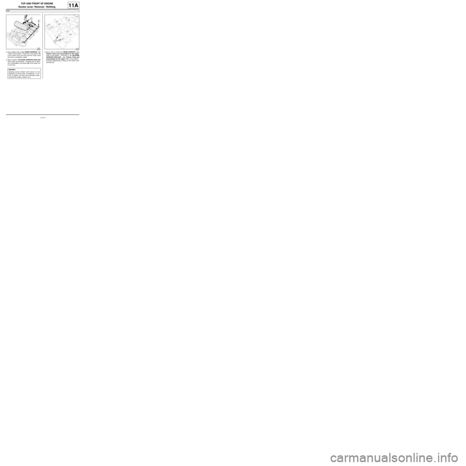
aUse a stipple roller to apply RESIN ADHESIVE (see
) (04B, Consumables - Products) on the section (A)
of the rocker cover joint face until the rocker cover
joint face is completely coated.
aApply a bead of SILICONE ADHESIVE SEALANT
(see ) (04B, Consumables - Products) with a diame-
ter of 1 to 2 mm on the section (B) of the rocker cov-
er joint face.aUse a cloth to remove the RESIN ADHESIVE (see
Vehicle: Parts and consumables for the repair)
(04B, Consumables - Products) or the SILICONE
ADHESIVE SEALANT (see Vehicle: Parts and
consumables for the repair) (04B, Consumables -
Products) (depending on fitting) on the rocker cover
bearings (C) .
145782
WARNING
Applying excess sealant could cause it to be
squeezed out when parts are tightened. A mix-
ture of sealant and fluid could damage certain
components (engine, radiator, etc.).
126216