wiring RENAULT TWINGO RS 2009 2.G Engine And Peripherals Service Manual
[x] Cancel search | Manufacturer: RENAULT, Model Year: 2009, Model line: TWINGO RS, Model: RENAULT TWINGO RS 2009 2.GPages: 652
Page 301 of 652
12A-36
FUEL MIXTURE
Inlet distributor: Removal - Refitting
D4F, and 772
12A
III - FINAL OPERATION
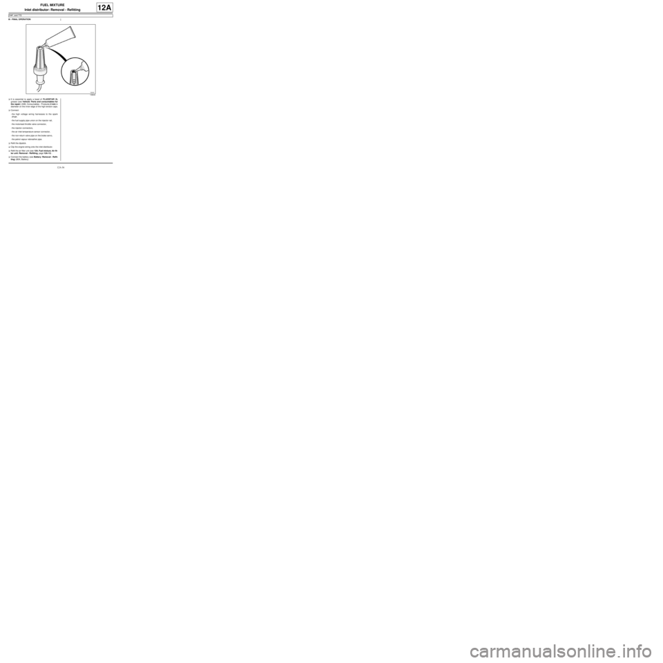
aIt is essential to apply a bead of FLUOSTAR 2L
grease (see Vehicle: Parts and consumables for
the repair) (04B, Consumables - Products) 2 mm in
diameter on the inner edge of the high tension caps.
aConnect:
-the high voltage wiring harnesses to the spark
plugs,
-the fuel supply pipe union on the injector rail,
-the motorised throttle valve connector,
-the injector connectors,
-the air inlet temperature sensor connector,
-the non-return valve pipe on the brake servo,
-the petrol vapour rebreather pipe.
aRefit the dipstick.
aClip the engine wiring onto the inlet distributor.
aRefit the air filter unit (see 12A, Fuel mixture, Air fil-
ter unit: Removal - Refitting, page 12A-13) .
aConnect the battery (see Battery: Removal - Refit-
ting) (80A, Battery).
106640
Page 303 of 652
12A-38
FUEL MIXTURE
Inlet distributor: Removal - Refitting
D4F, and 780 or 782
12A
aRemove the « injector rail - injector » assembly (see
17B, Petrol injection, Injector rail - Injectors: Re-
moval - Refitting, page 17B-27) .
II - OPERATION FOR REMOVAL OF PART
CONCERNED
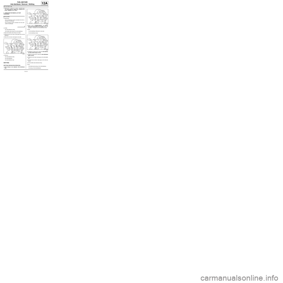
aDisconnect:
-the air temperature sensor connector from the in-
tercooler air outlet pipe,
-the air pressure sensor connector from the inter-
cooler air outlet pipe.
aUnclip:
-the inlet distributor wiring,
-the throttle valve wiring on the inlet distributor.
aMove the throttle valve wiring to one side.
aDisconnect the non-return valve pipe from the inlet
distributor.
aMove the non-return valve pipe to one side.
aRemove:
-the inlet distributor bolts,
-the inlet distributor,
-the inlet distributor seal.
REFITTING
REFITTING PREPARATION OPERATION
aparts always to be replaced: inlet distributor
seal.aApply a drop of FRENETANCHE (see Vehicle:
Parts and consumables for the repair) (04B, Con-
sumables - Products) to the inlet distributor bolts.
aRefit:
-the inlet distributor fitted with a new seal,
-the inlet distributor bolts.
aPretighten to torque and in order the inlet distribu-
tor bolts (initial torque) (4 N.m).
aTighten to torque and in order the inlet distributor
bolts (12 N.m).
aPosition the non-return valve pipe on the inlet distrib-
utor.
aConnect the non-return valve pipe on the inlet dis-
tributor.
aFit the throttle valve electrical wiring.
aClip:
-the throttle valve wiring on the inlet distributor,
-the wiring on the inlet distributor. D4F, and 780
120955
120955
120955
Page 306 of 652
12A-41
FUEL MIXTURE
Inlet distributor: Removal - Refitting
K4M
12A
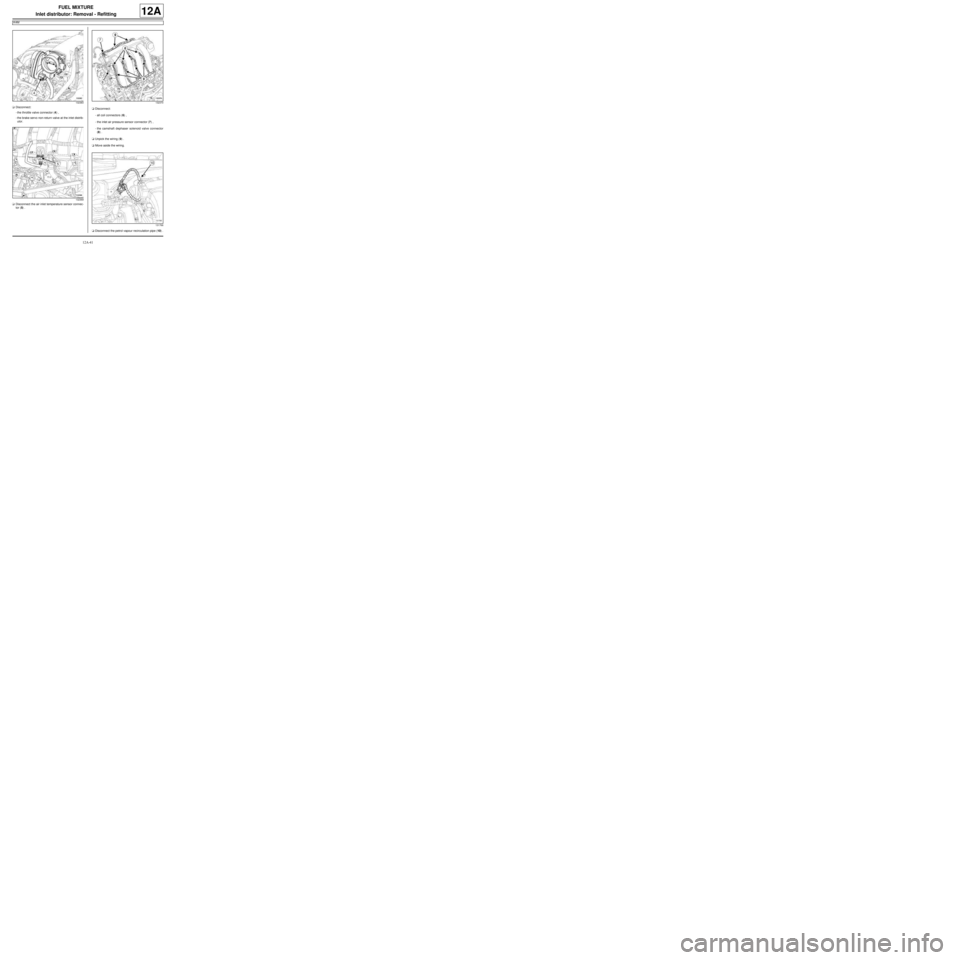
aDisconnect:
-the throttle valve connector (4) ,
-the brake servo non-return valve at the inlet distrib-
utor.
aDisconnect the air inlet temperature sensor connec-
tor (5) .aDisconnect:
-all coil connectors (6) ,
-the inlet air pressure sensor connector (7) ,
-the camshaft dephaser solenoid valve connector
(8) .
aUnpick the wiring (9) .
aMove aside the wiring.
aDisconnect the petrol vapour recirculation pipe (10) .
132383
132369132370
131766
Page 308 of 652
12A-43
FUEL MIXTURE
Inlet distributor: Removal - Refitting
K4M
12A
aFit new seals to the inlet distributor.
When replacing the inlet distributor
aparts always to be replaced: Throttle valve seal.
aUse SURFACE CLEANER (see Vehicle: Parts
and consumables for the repair) (04B, Consuma-
bles - Products) to clean and degrease:
-the throttle valve joint face if it is to be re-used,
-the inlet distributor seal housing.
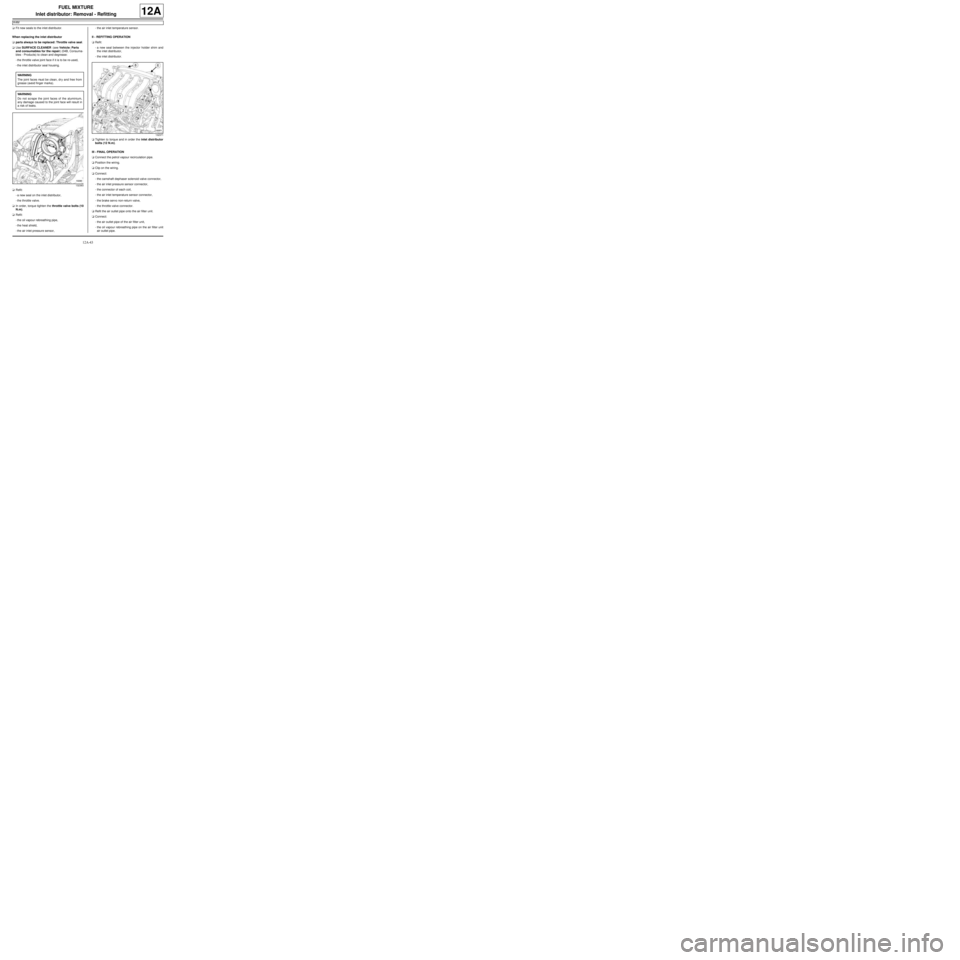
aRefit:
-a new seal on the inlet distributor,
-the throttle valve.
aIn order, torque tighten the throttle valve bolts (10
N.m).
aRefit:
-the oil vapour rebreathing pipe,
-the heat shield,
-the air inlet pressure sensor,-the air inlet temperature sensor.
II - REFITTING OPERATION
aRefit:
-a new seal between the injector holder shim and
the inlet distributor,
-the inlet distributor.
aTighten to torque and in order the inlet distributor
bolts (12 N.m).
III - FINAL OPERATION
aConnect the petrol vapour recirculation pipe.
aPosition the wiring.
aClip on the wiring.
aConnect:
-the camshaft dephaser solenoid valve connector,
-the air inlet pressure sensor connector,
-the connector of each coil,
-the air inlet temperature sensor connector,
-the brake servo non-return valve,
-the throttle valve connector.
aRefit the air outlet pipe onto the air filter unit.
aConnect:
-the air outlet pipe of the air filter unit,
-the oil vapour rebreathing pipe on the air filter unit
air outlet pipe. WARNING
The joint faces must be clean, dr y and free from
grease (avoid finger marks).
WARNING
Do not scrape the joint faces of the aluminium,
any damage caused to the joint face will result in
a risk of leaks.
132383
132371
Page 321 of 652
12A-56
FUEL MIXTURE
Exhaust manifold: Removal - Refitting
K4M
12A
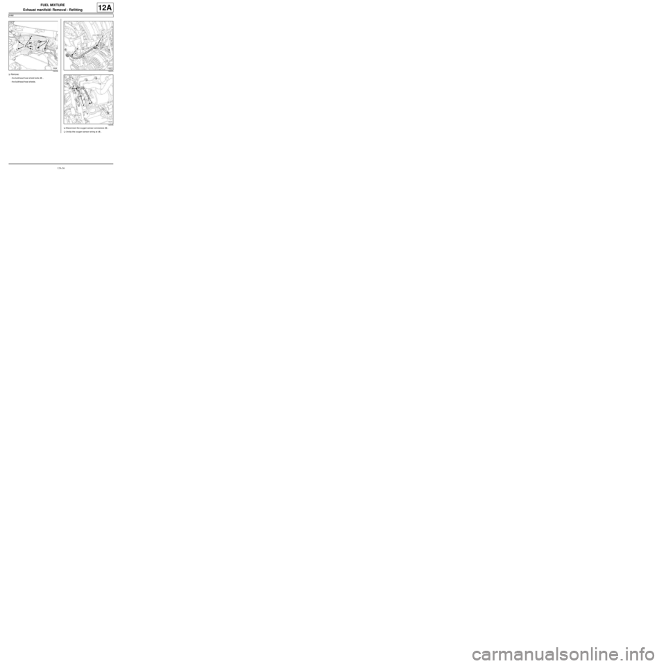
aRemove:
-the bulkhead heat shield bolts (2) ,
-the bulkhead heat shields.
aDisconnect the oxygen sensor connectors (3) .
aUnclip the oxygen sensor wiring at (4) .
132436132373
132378
Page 324 of 652
12A-59
FUEL MIXTURE
Exhaust manifold: Removal - Refitting
K4M
12A
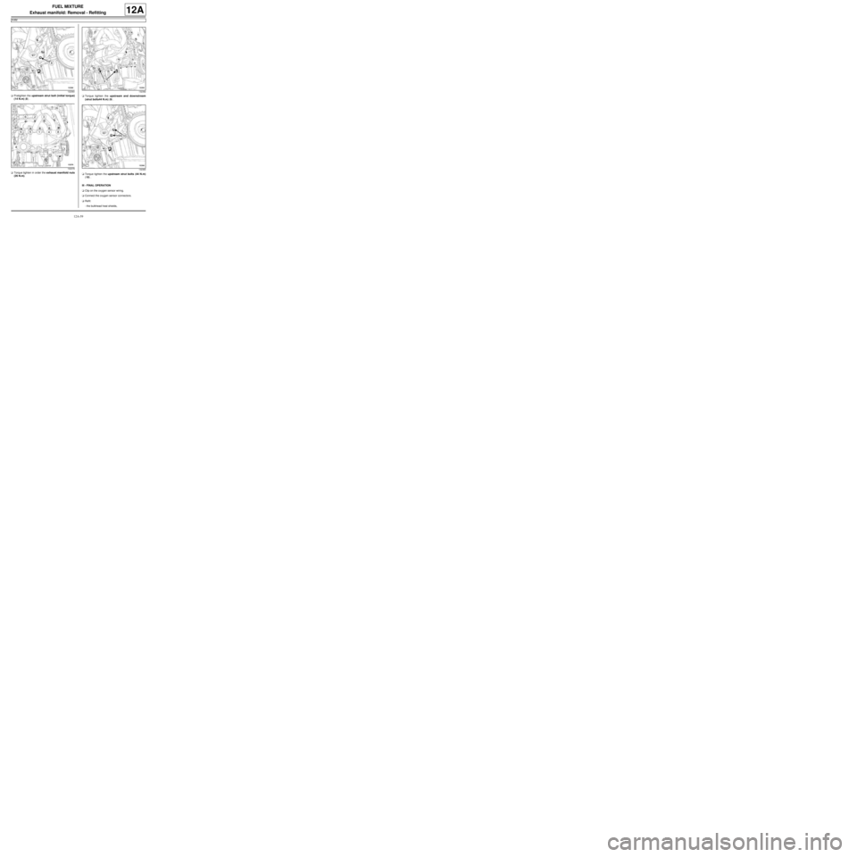
aPretighten the upstream strut bolt (initial torque)
(14 N.m) (8) .
aTorque tighten in order the exhaust manifold nuts
(26 N.m).aTorque tighten the upstream and downstream
(strut bolts44 N.m) (9) .
aTorque tighten the upstream strut bolts (44 N.m)
(10) .
III - FINAL OPERATION
aClip on the oxygen sensor wiring.
aConnect the oxygen sensor connectors.
aRefit:
-the bulkhead heat shields,
132360
132379132392
132360
Page 334 of 652
12B-9
TURBOCHARGING
Turbocharger: Removal - Refitting
D4F, and 780 or 782
12B
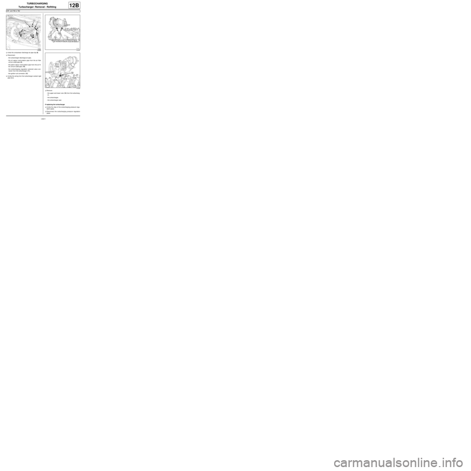
aUndo the compressor discharge air pipe clip (8) .
aDisconnect:
-the turbocharger discharge air pipe,
-the oil vapour recirculation pipe from the air filter
unit air outlet pipe (9) ,
-the petrol vapour recirculation pipe from the air fil-
ter unit air outlet pipe (10) ,
-the turbocharging regulation solenoid valve con-
nector from the turbocharger (11) ,
-the ignition coil connector (12) .
aUnclip the wiring from the turbocharger coolant rigid
pipe strut.
aRemove:
-the upper and lower nuts (13) from the turbocharg-
er,
-the turbocharger,
-the turbocharger seal.
If replacing the turbocharger
aUnclip the clips of the turbocharging pressure regu-
lation pipes.
aDisconnect the turbocharging pressure regulation
pipes.
122826121201
121202
Page 335 of 652
12B-10
TURBOCHARGING
Turbocharger: Removal - Refitting
D4F, and 780 or 782
12B
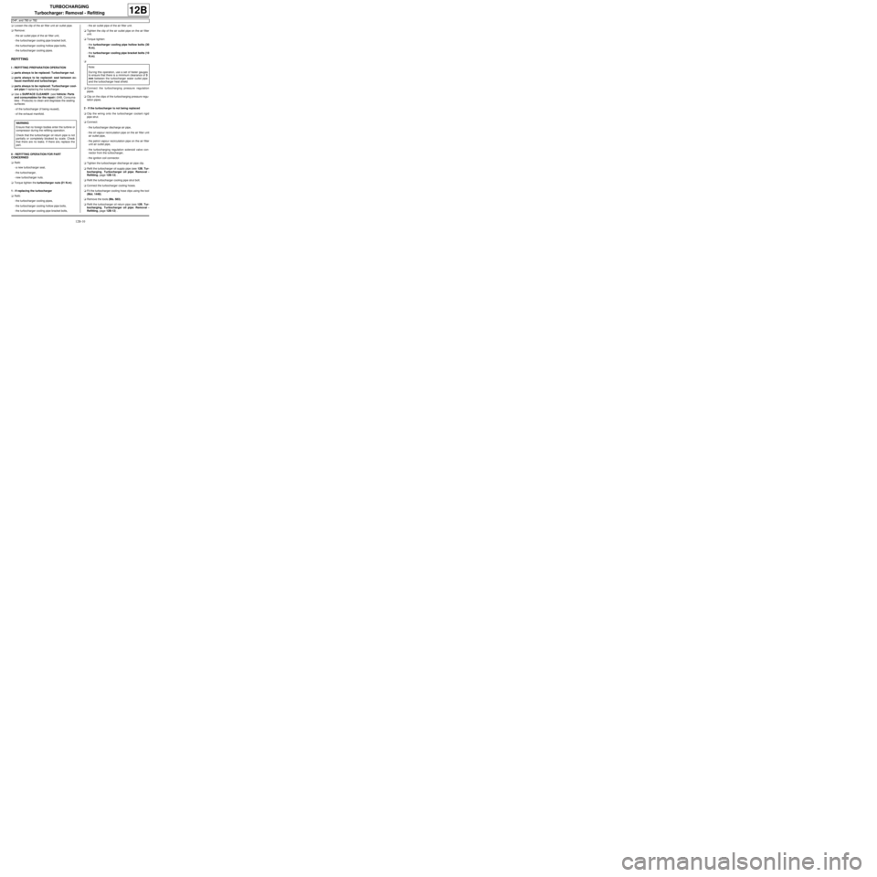
aLoosen the clip of the air filter unit air outlet pipe.
aRemove:
-the air outlet pipe of the air filter unit,
-the turbocharger cooling pipe bracket bolt,
-the turbocharger cooling hollow pipe bolts,
-the turbocharger cooling pipes.
REFITTING
I - REFITTING PREPARATION OPERATION
aparts always to be replaced: Turbocharger nut.
aparts always to be replaced: seal between ex-
haust manifold and turbocharger.
aparts always to be replaced: Turbocharger cool-
ant pipe if replacing the turbocharger.
aUse a SURFACE CLEANER (see Vehicle: Parts
and consumables for the repair) (04B, Consuma-
bles - Products) to clean and degrease the sealing
surfaces:
-of the turbocharger (if being reused),
-of the exhaust manifold.
II - REFITTING OPERATION FOR PART
CONCERNED
aRefit:
-a new turbocharger seal,
-the turbocharger,
-new turbocharger nuts.
aTorque tighten the turbocharger nuts (21 N.m).
1 - If replacing the turbocharger
aRefit:
-the turbocharger cooling pipes,
-the turbocharger cooling hollow pipe bolts,
-the turbocharger cooling pipe bracket bolts,-the air outlet pipe of the air filter unit.
aTighten the clip of the air outlet pipe on the air filter
unit.
aTorque tighten:
-the turbocharger cooling pipe hollow bolts (30
N.m),
-the turbocharger cooling pipe bracket bolts (10
N.m).
a
aConnect the turbocharging pressure regulation
pipes.
aClip on the clips of the turbocharging pressure regu-
lation pipes.
2 - If the turbocharger is not being replaced
aClip the wiring onto the turbocharger coolant rigid
pipe strut.
aConnect:
-the turbocharger discharge air pipe,
-the oil vapour recirculation pipe on the air filter unit
air outlet pipe,
-the petrol vapour recirculation pipe on the air filter
unit air outlet pipe,
-the turbocharging regulation solenoid valve con-
nector from the turbocharger,
-the ignition coil connector.
aTighten the turbocharger discharge air pipe clip.
aRefit the turbocharger oil supply pipe (see 12B, Tur-
bocharging, Turbocharger oil pipe: Removal -
Refitting, page 12B-12) .
aRefit the turbocharger cooling pipe strut bolt.
aConnect the turbocharger cooling hoses.
aFit the turbocharger cooling hose clips using the tool
(Mot. 1448).
aRemove the tools (Ms. 583).
aRefit the turbocharger oil return pipe (see 12B, Tur-
bocharging, Turbocharger oil pipe: Removal -
Refitting, page 12B-12) . WARNING
Ensure that no foreign bodies enter the turbine or
compressor during the refitting operation.
Check that the turbocharger oil return pipe is not
partially or completely blocked by scale. Check
that there are no leaks. If there are, replace the
part.Note:
Dur ing this operation, use a set of feeler gauges
to ensure that there is a minimum clearance of 3
mm between the turbocharger water outlet pipe
and the turbocharger heat shield.
Page 348 of 652
13A-5
FUEL SUPPLY
Fuel filter: Removal - Refitting
K9K
13A
II - OPERATION FOR REMOVAL OF PART
CONCERNED
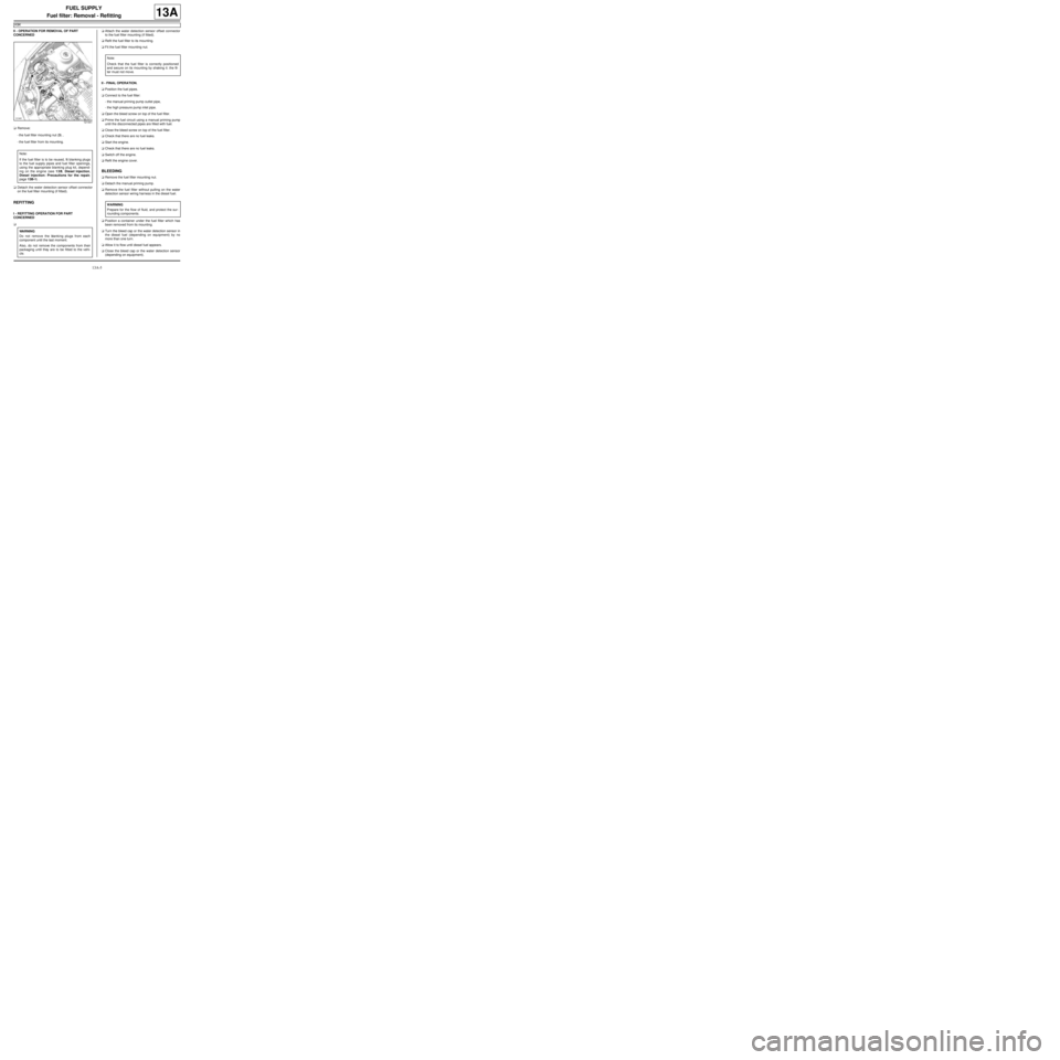
aRemove:
-the fuel filter mounting nut (3) ,
-the fuel filter from its mounting.
aDetach the water detection sensor offset connector
on the fuel filter mounting (if fitted).
REFITTING
I - REFITTING OPERATION FOR PART
CONCERNED
aaAttach the water detection sensor offset connector
to the fuel filter mounting (if fitted).
aRefit the fuel filter to its mounting.
aFit the fuel filter mounting nut.
II - FINAL OPERATION.
aPosition the fuel pipes.
aConnect to the fuel filter:
-the manual priming pump outlet pipe,
-the high pressure pump inlet pipe.
aOpen the bleed screw on top of the fuel filter.
aPrime the fuel circuit using a manual priming pump
until the disconnected pipes are filled with fuel.
aClose the bleed screw on top of the fuel filter.
aCheck that there are no fuel leaks.
aStart the engine.
aCheck that there are no fuel leaks.
aSwitch off the engine.
aRefit the engine cover.
BLEEDING
aRemove the fuel filter mounting nut.
aDetach the manual priming pump.
aRemove the fuel filter without pulling on the water
detection sensor wiring harness in the diesel fuel.
aPosition a container under the fuel filter which has
been removed from its mounting.
aTurn the bleed cap or the water detection sensor in
the diesel fuel (depending on equipment) by no
more than one turn.
aAllow it to flow until diesel fuel appears.
aClose the bleed cap or the water detection sensor
(depending on equipment).
121441
Note:
If the fuel filter is to be reused, fit blanking plugs
to the fuel supply pipes and fuel filter openings,
using the appropriate blanking plug kit, depend-
ing on the engine (see 13B, Diesel injection,
Diesel injection: Precautions for the repair,
page 13B-1) .
WARNING
Do not remove the blanking plugs from each
component until the last moment.
Also, do not remove the components from their
packaging until they are to be fitted to the vehi-
cle.
Note:
Chec k that the fuel filter is correctly positioned
and secure on its mounting by shaking it: the fil-
ter must not move.
WARNING
Prepare for the flow of fluid, and protect the sur-
rounding components.
Page 378 of 652
13B-17
DIESEL INJECTION
High pressure pump: Removal - Refitting
K9K
13B
a
Clean the union on the diesel fuel supply pipe high
pressure pump (see 13B, Diesel injection, Diesel
injection: Precautions for the repair, page 13B-1)
.
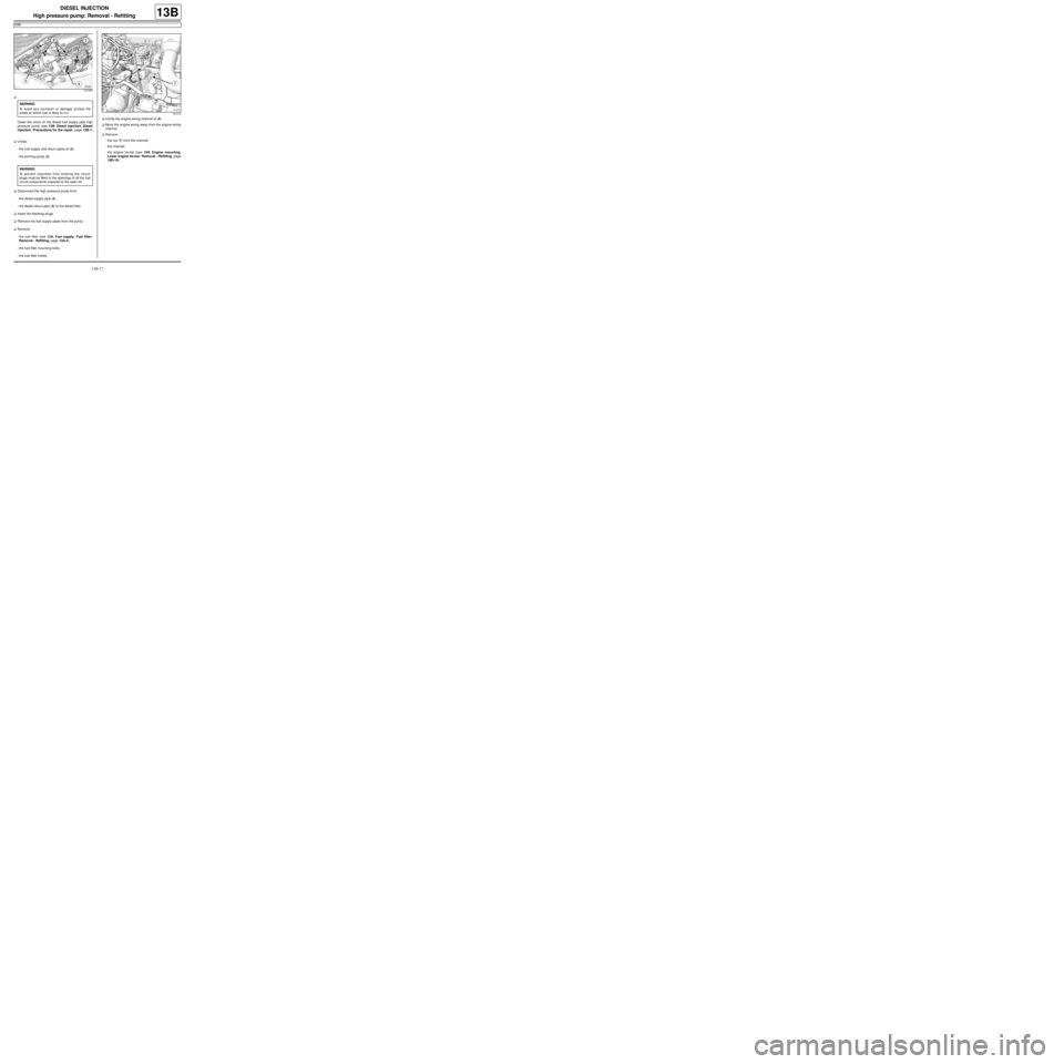
aUnclip:
-the fuel supply and return pipes at (2) ,
-the priming pump (3) .
aDisconnect the high pressure pump from:
-the diesel supply pipe (4) ,
-the diesel return pipe (5) to the diesel filter.
aInsert the blanking plugs.
aRemove the fuel supply pipes from the pump.
aRemove:
-the fuel filter (see 13A, Fuel supply, Fuel filter:
Removal - Refitting, page 13A-4) ,
-the fuel filter mounting bolts,
-the fuel filter holder,aUnclip the engine wiring channel at (6) .
aMove the engine wiring away from the engine wiring
channel.
aRemove:
-the nut (7) from the channel,
-the channel,
-the engine tie-bar (see 19D, Engine mounting,
Lower engine tie-bar: Removal - Refitting, page
19D-18) .
121423
WARNING
To avoid any corrosion or damage, protect the
areas on which fuel is likely to run.
WARNING
To prevent impurities from entering the circuit,
plugs must be fitted to the openings of all the fuel
circuit components exposed to the open air.
121419