K4M RENAULT TWINGO RS 2009 2.G Engine And Peripherals Repair Manual
[x] Cancel search | Manufacturer: RENAULT, Model Year: 2009, Model line: TWINGO RS, Model: RENAULT TWINGO RS 2009 2.GPages: 652
Page 229 of 652
11A-112
TOP AND FRONT OF ENGINE
Camshaft: Removal - Refitting
K4M
11A
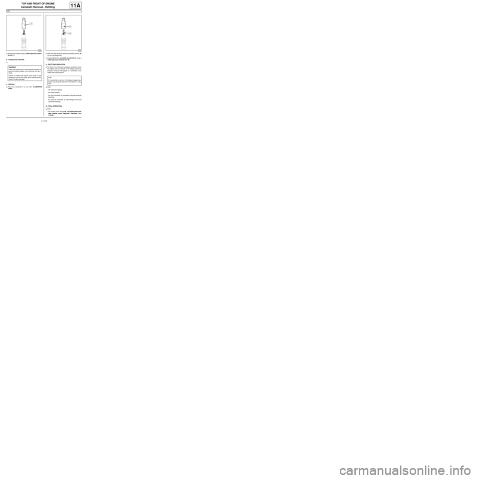
aRemove the dowel using a roller-type stud remov-
al tool (7) .
b - Cleaning the camshaft
a
c - Refitting
aPlace the camshaft in a vice with ALUMINIUM
JAWS.aRefit the new camshaft dowel (precoated section (8)
on the camshaft side).
aTorque tighten the camshaft dowel (8 N.m) using a
roller-type stud removal tool (9) .
II - REFITTING OPERATION
aTo check if re-priming is necessary, press the top of
the tappet with your thumb. If the tappet piston de-
presses, immerse the tappets in a container full of
diesel then reprime them.
aRefit:
-the hydraulic tappets,
-the valve rockers,
-the inlet camshaft, by lubricating the inlet camshaft
bearings,
-the exhaust camshaft, by lubricating the exhaust
camshaft bearings.
III - FINAL OPERATION
aRefit:
-the rocker cover (see 11A, Top and front of en-
gine, Rocker cover: Removal - Refitting, page
11A-66) ,
109050
WARNING
Clean the thread hole of the camshaft carefully to
prevent foreign bodies from entering the cam-
shaft.
Failure to follow this advice could lead to the
blocking of the oil inlet holes, which would quickly
result in engine damage.
109050
Note:
It is essential to repr ime the hydraulic tappets as
these may become drained if removed for a long
time.
Page 230 of 652
11A-113
TOP AND FRONT OF ENGINE
Camshaft: Removal - Refitting
K4M
11A
-the camshaft seals on the timing end (see 11A,
Top and front of engine, Camshaft seal, timing
end: Removal - Refitting, page 11A-138) ,
-the camshaft dephaser (see 11A, Top and front of
engine, Camshaft dephaser: Removal - Refit-
ting, page 11A-135) ,
-the timing belt (see 11A, Top and front of engine,
Timing belt: Removal - Refitting, page 11A-27) ,
-the crankshaft accessories pulley (see 11A, Top
and front of engine, Crankshaft accessories
pulley: Removal - Refitting, page 11A-20) ,
-the right-hand suspended engine mounting (see
19D, Engine mounting, Right-hand suspended
engine mounting: Removal - Refitting, page
19D-13) ,
-the air filter unit (see 12A, Fuel mixture, Air filter
unit: Removal - Refitting, page 12A-13) ,
-the accessories belt (see 11A, Top and front of
engine, Accessories belt: Removal - Refitting,
page 11A-3) ,
-the front upper cross member (see Front upper
cross member: Removal - Refitting) (42A, Upper
front structure),
-the bonnet catch (see Bonnet lock: Removal -
Refitting) (52A, Non-side opening element mecha-
nisms),
-the headlights (see Halogen headlight: Removal
- Refitting) (80B, Headlights),
-the front bumper (see Front bumper: Removal -
Refitting) (55A, Exterior protection),
-the front right-hand wheel arch liner (see Front
wheel arch liner: Removal - Refitting) (55A, Ex-
terior protection),
-the front right-hand wheel (see Wheel: Removal -
Refitting) (35A, Wheels and tyres),
-the engine undertray,
-the oil decanter (see 11A, Top and front of en-
gine, Oil decanter: Removal - Refitting, page
11A-147) ,
-the inlet distributor (see 12A, Fuel mixture, Inlet
distributor: Removal - Refitting, page 12A-29) ,
-the throttle valve (see 12A, Fuel mixture, Throttle
valve: Removal - Refitting, page 12A-20) ,
-the coils (see 17A, Ignition, Coils: Removal - Re-
fitting, page 17A-1) ,
-the scoop under the scuttle panel grille (see Scoop
under the scuttle panel grille: Removal - Refit-
ting) (56A, Exterior equipment),-the scuttle panel grille (see Scuttle panel grille:
Removal - Refitting) (56A, Exterior equipment),
-the windscreen wiper arms (see Windscreen wip-
er arm: Removal - Refitting) (85A, Wiping -
Washing).
aConnect the battery (see Battery: Removal - Refit-
ting) (80A, Battery).
Page 236 of 652
11A-119
TOP AND FRONT OF ENGINE
Cylinder head: Removal - Refitting
K4M
11A
REMOVAL
I - REMOVAL PREPARATION OPERATION
aPosition the vehicle on a two-post lift (see Vehicle:
Towing and lifting) (02A, Lifting equipment).
aDisconnect the battery (see Battery: Removal - Re-
fitting) (80A, Battery).
aRemove the engine undertray.
aDrain the cooling system (see 19A, Cooling, Cool-
ing system: Draining - Refilling, page 19A-9) .
aRemove:
-the windscreen wiper arms (see Windscreen wip-
er arm: Removal - Refitting) (85A, Wiping -
Washing),
-the scuttle panel grille (see Scuttle panel grille:
Removal - Refitting) (56A, Exterior equipment),
-the scoop under the scuttle panel grille (see Scoop
under the scuttle panel grille: Removal - Refit-
ting) (56A, Exterior equipment),
-the coils (see 17A, Ignition, Coils: Removal - Re-
fitting, page 17A-1) ,-the throttle valve (see 12A, Fuel mixture, Throttle
valve: Removal - Refitting, page 12A-20) ,
-the inlet distributor (see 12A, Fuel mixture, Inlet
distributor: Removal - Refitting, page 12A-29) ,
-the oil decanter (see 11A, Top and front of en-
gine, Oil decanter: Removal - Refitting, page
11A-147) ,
-the front right-hand wheel (see Wheel: Removal -
Refitting) (35A, Wheels and tyres),
-the front right-hand wheel arch liner (see Front
wheel arch liner: Removal - Refitting) (55A, Ex-
terior protection),
-the front bumper (see Front bumper: Removal -
Refitting) (55A, Exterior protection),
-the headlights (see Halogen headlight: Removal
- Refitting) (80B, Headlights),
-the bonnet catch (see Bonnet lock: Removal -
Refitting) (52A, Non-side opening element mecha-
nisms),
-the front upper cross member (see Front upper
cross member: Removal - Refitting) (42A, Upper
front structure),
-the accessories belt (see 11A, Top and front of
engine, Accessories belt: Removal - Refitting,
page 11A-3) ,
-the air filter unit (see 12A, Fuel mixture, Air filter
unit: Removal - Refitting, page 12A-13) ,
-the lower engine tie-bar (see 19D, Engine mount-
ing, Lower engine tie-bar: Removal - Refitting,
page 19D-18) ,
-the right-hand suspended engine mounting (see
19D, Engine mounting, Right-hand suspended
engine mounting: Removal - Refitting, page
19D-13) ,
-the crankshaft accessories pulley (see 11A, Top
and front of engine, Crankshaft accessories
pulley: Removal - Refitting, page 11A-20) ,
-the timing belt (see 11A, Top and front of engine,
Timing belt: Removal - Refitting, page 11A-27) ,
-the camshaft dephaser (see 11A, Top and front of
engine, Camshaft dephaser: Removal - Refit-
ting, page 11A-135) ,
-the camshaft seals on the timing end (see 11A,
Top and front of engine, Camshaft seal, timing
end: Removal - Refitting, page 11A-138) ,
-the rocker cover (see 11A, Top and front of en-
gine, Rocker cover: Removal - Refitting, page
11A-66) , Special tooling required
Mot. 1448Remote operation pliers for
hose clips .
Mot. 1202-01Clip pliers for hose clips
(large size).
Mot. 1202-02Clip pliers for hose clips
(small size)
Tightening torquesm
cylinder head bolts (ini-
tial torque)20 N.m
cylinder head bolts240˚ ±± ± ±
6˚
IMPORTANT
Wear cut-resistant gloves during the operation.
IMPORTANT
Wear leaktight gloves (Nitrile type) for this opera-
tion.
Page 237 of 652
11A-120
TOP AND FRONT OF ENGINE
Cylinder head: Removal - Refitting
K4M
11A
-the camshafts (see 11A, Top and front of engine,
Camshaft: Removal - Refitting, page 11A-82) .
aDrain the gearbox (see Manual gearbox oils:
Draining - Filling) (21A, Manual gearbox).
aRemove:
-the front right-hand wheel driveshaft (see Front
right-hand driveshaft: Removal - Refitting)
(29A, Driveshafts),
-the exhaust manifold (see 12A, Fuel mixture, Ex-
haust manifold: Removal - Refitting, page 12A-
48) .
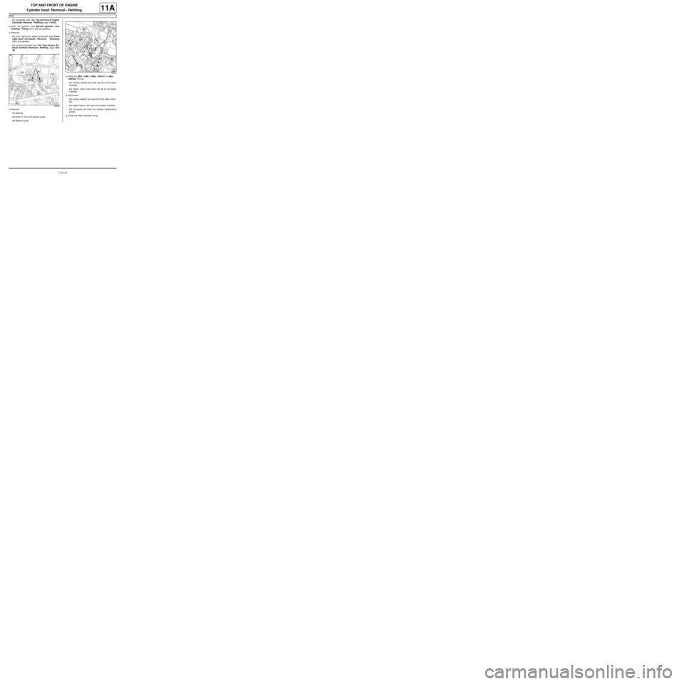
aRemove:
-the dipstick,
-the bolts (1) from the dipstick guide,
-the dipstick guide.aUsing the (Mot. 1448) or (Mot. 1202-01) or (Mot.
1202-02) remove:
-the cooling radiator top hose clip (2) on the water
chamber.
-the heater matrix inlet hose clip (3) on the water
chamber.
aDisconnect:
-the cooling radiator top hose from the water cham-
ber.
-the heater matrix inlet hose of the water chamber,
-the connector (4) from the coolant temperature
sensor.
aUnclip the water chamber wiring.
132368
128616
Page 238 of 652

11A-121
TOP AND FRONT OF ENGINE
Cylinder head: Removal - Refitting
K4M
11A
aRemove:
-the bolts (5) of the engine wiring channel,
-the wiring bracket bolt (6) .
aMove the wiring bracket away from the water cham-
ber.
aDisconnect the injector connectors (7) .
aMove the injector wiring to one side.II - REMOVAL OPERATION
aRemove:
-the cylinder head bolts,
-the cylinder head,
-the cylinder head gasket.
REMOVAL
I - REFITTING PREPARATION OPERATION
aparts always to be replaced: cylinder head bolts.
parts always to be replaced: Cylinder head gas-
ket.
127347
132390
103259
Page 239 of 652

11A-122
TOP AND FRONT OF ENGINE
Cylinder head: Removal - Refitting
K4M
11A
CLEANING THE CYLINDER HEAD
a
aUse SUPER CLEANING AGENT FOR JOINT FA-
CES (see Vehicle: Parts and consumables for
the repair) (04B, Consumables - Products) to clean:
-the cylinder head gasket face if being reused,
-the cylinder block gasket face.
aUse SURFACE CLEANER (see Vehicle: Parts
and consumables for the repair) (04B, Consuma-
bles - Products) to degrease:
-the cylinder head gasket face if being reused,
-the cylinder block gasket face.
aCheck for gasket face deformation using a ruler and
a set of shims.
The maximum deformation is 0.05 mm.aStrip the cylinder head (see Cylinder head: Strip-
ping - Rebuilding) (Technical Note 6023A, 10A,
Engine and peripherals).
aTest the cylinder head for possible cracks using the
cylinder head test kit (see Garage Equipment Cat-
alogue).
aRebuild the cylinder head (see Cylinder head:
Stripping - Rebuilding) (Technical Note 6023A,
10A, Engine and peripherals).
aPosition the pistons at mid-stroke.
aCheck that the centring dowel (6) is on the cylinder
block.
aRefit a new cylinder head gasket. IMPORTANT
Wear goggles with side protectors for this opera-
tion.
IMPORTANT
Wear leaktight gloves (Nitrile type) for this opera-
tion.
WARNING
Do not scrape the joint faces of the aluminium,
any damage caused to the joint face will result in
a risk of leaks.
WARNING
The joint faces must be clean, dr y and free from
grease (avoid finger marks).
WARNING
Do not allow this product to drip onto the paint-
work.
Clean the cylinder head carefully to prevent for-
eign bodies from entering the oil supply and
return galleries.
Failure to follow this advice could lead to the
blocking of the various oil inlet galleries, which
would quickly result in engine damage.
WARNING
No regrinding of the cylinder head is permitted.
128611
Page 240 of 652

11A-123
TOP AND FRONT OF ENGINE
Cylinder head: Removal - Refitting
K4M
11A
II - REFITTING OPERATION
aRefit:
-the cylinder head,
-the new cylinder head bolts.
aWithout tightening, fit the cylinder head bolts in or-
der.
aPretighten to torque and in order the cylinder head
bolts (initial torque) (20 N.m).
aCheck that all of the new cylinder head bolts are
tightened to the correct torque (20 N.m).
aAngle tighten in order the cylinder head bolts (240˚
±± ± ±
6˚).III - FINAL OPERATION
aPosition the injector wiring.
aConnect the injector connectors.
aFit the wiring bracket on the water chamber.
aRefit:
-the wiring bracket bolt on the water chamber,
-the bolts of the engine wiring channel.
aClip on the water chamber wiring.
aConnect:
-the coolant temperature sensor connector,
-the heater matrix inlet hose to the water chamber,
-the cooling radiator top hose to the water chamber.
aUsing the (Mot. 1448) or (Mot. 1202-01) or (Mot.
1202-02) fit:
-the cooling radiator top hose clip on the water
chamber,
-the heater matrix inlet hose clip on the water cham-
ber.
aRefit:
-dipstick guide ,
-the dipstick,
-the exhaust manifold (see 12A, Fuel mixture, Ex-
haust manifold: Removal - Refitting, page 12A-
48) .
-the front right-hand wheel driveshaft (see Front
right-hand driveshaft: Removal - Refitting)
(29A, Driveshafts),
-the camshafts (see 11A, Top and front of engine,
Camshaft: Removal - Refitting, page 11A-82) ,
-the rocker cover (see 11A, Top and front of en-
gine, Rocker cover: Removal - Refitting, page
11A-66) ,
-the camshaft seals on the timing end (see 11A,
Top and front of engine, Camshaft seal, timing
end: Removal - Refitting, page 11A-138) ,
-the camshaft dephaser (see 11A, Top and front of
engine, Camshaft dephaser: Removal - Refit-
ting, page 11A-135) ,
-the timing belt (see 11A, Top and front of engine,
Timing belt: Removal - Refitting, page 11A-27) ,
-the crankshaft accessories pulley (see 11A, Top
and front of engine, Crankshaft accessories
pulley: Removal - Refitting, page 11A-20) ,
103259
WARNING
In order to ensure that the bolts are correctly
tightened, use a syringe to remove any oil which
may be in the cylinder head mounting holes.
WARNING
Do not oil the new bolts. Be sure to oil bolts
being reused.
WARNING
Do not retighten the cylinder head bolts after
applying this procedure.
Page 241 of 652
11A-124
TOP AND FRONT OF ENGINE
Cylinder head: Removal - Refitting
K4M
11A
-the right-hand suspended engine mounting (see
19D, Engine mounting, Right-hand suspended
engine mounting: Removal - Refitting, page
19D-13) ,
-the lower engine tie-bar (see 19D, Engine mount-
ing, Lower engine tie-bar: Removal - Refitting,
page 19D-18) ,
-the air filter unit (see 12A, Fuel mixture, Air filter
unit: Removal - Refitting, page 12A-13) ,
-the accessories belt (see 11A, Top and front of
engine, Accessories belt: Removal - Refitting,
page 11A-3) ,
-the front upper cross member (see Front upper
cross member: Removal - Refitting) (42A, Upper
front structure),
-the bonnet catch (see Bonnet lock: Removal -
Refitting) (52A, Non-side opening element mecha-
nisms),
-the headlights (see Halogen headlight: Removal
- Refitting) (80B, Headlights),
-the front bumper (see Front bumper: Removal -
Refitting) (55A, Exterior protection),
-the front right-hand wheel arch liner (see Front
wheel arch liner: Removal - Refitting) (55A, Ex-
terior protection),
-the front right-hand wheel (see Wheel: Removal -
Refitting) (35A, Wheels and tyres),
-the oil decanter (see 11A, Top and front of en-
gine, Oil decanter: Removal - Refitting, page
11A-147) ,
-the inlet distributor (see 12A, Fuel mixture, Inlet
distributor: Removal - Refitting, page 12A-29) ,
-the throttle valve (see 12A, Fuel mixture, Throttle
valve: Removal - Refitting, page 12A-20) ,
-the coils (see 17A, Ignition, Coils: Removal - Re-
fitting, page 17A-1) ,
-the scoop under the scuttle panel grille (see Scoop
under the scuttle panel grille: Removal - Refit-
ting) (56A, Exterior equipment),
-the scuttle panel grille (see Scuttle panel grille:
Removal - Refitting) (56A, Exterior equipment),
-the windscreen wiper arms (see Windscreen wip-
er arm: Removal - Refitting) (85A, Wiping -
Washing).
aPerform the following operations:
-fill the gearbox (see Manual gearbox oils: Drain-
ing - Filling) (21A, Manual gearbox).-fill and bleed the coolant circuit (see 19A, Cooling,
Cooling system: Draining - Refilling, page 19A-
9) .
aRefit the engine undertray.
aConnect the battery (see Battery: Removal - Refit-
ting) (80A, Battery).
Page 252 of 652
11A-135
TOP AND FRONT OF ENGINE
Camshaft dephaser: Removal - Refitting
K4M
11A
REMOVAL
I - REMOVAL PREPARATION OPERATION
aPosition the vehicle on a two-post lift (see Vehicle:
Towing and lifting) (02A, Lifting equipment).
aDisconnect the battery (see Battery: Removal - Re-
fitting) (80A, Battery).
aRemove:
-the engine undertray,
-the front right-hand wheel (see Wheel: Removal -
Refitting) (35A, Wheels and tyres),
-the front right-hand wheel arch liner (see Front
wheel arch liner: Removal - Refitting) (55A, Ex-
terior protection),
-the front bumper (see Front bumper: Removal -
Refitting) (55A, Exterior protection),
-the headlights (see Halogen headlight: Removal
- Refitting) (80B, Headlights),
-the bonnet catch (see Bonnet lock: Removal -
Refitting) (52A, Non-side opening element mecha-
nisms),
-the front upper cross member (see Front upper
cross member: Removal - Refitting) (42A, Upper
front structure),
-the accessories belt (see 11A, Top and front of
engine, Accessories belt: Removal - Refitting,
page 11A-3) ,
-the air filter unit (see 12A, Fuel mixture, Air filter
unit: Removal - Refitting, page 12A-13) ,
-the throttle valve (see 12A, Fuel mixture, Throttle
valve: Removal - Refitting, page 12A-20) ,
-the windscreen wiper arms (see Windscreen wip-
er arm: Removal - Refitting) (85A, Wiping -
Washing),
-the scuttle panel grille (see Scuttle panel grille:
Removal - Refitting) (56A, Exterior equipment),
-the scoop under the scuttle panel grille (see Scoop
under the scuttle panel grille: Removal - Refit-
ting) (56A, Exterior equipment),-the right-hand suspended engine mounting (see
19D, Engine mounting, Right-hand suspended
engine mounting: Removal - Refitting, page
19D-13) ,
-the crankshaft accessories pulley (see 11A, Top
and front of engine, Crankshaft accessories
pulley: Removal - Refitting, page 11A-20) ,
-the timing belt (see 11A, Top and front of engine,
Timing belt: Removal - Refitting, page 11A-27) .
II - REMOVAL OPERATION
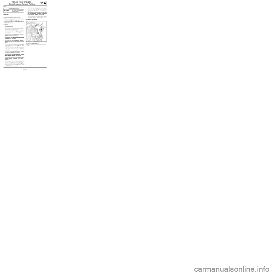
aPosition the (Mot. 1490-01) (1) .
aRemove the camshaft dephaser pulley blanking cov-
er (2) . Special tooling required
Mot. 1490-01For locking and adjusting the
camshaft pulle ys.
103265
Page 253 of 652
11A-136
TOP AND FRONT OF ENGINE
Camshaft dephaser: Removal - Refitting
K4M
11A
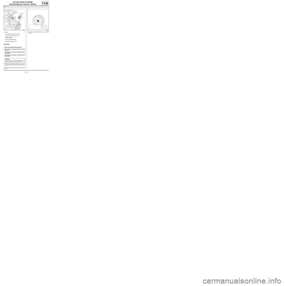
aRemove:
-the camshaft dephaser pulley bolt (3) ,
-the exhaust camshaft pulley nut (4) ,
-the (Mot. 1490-01),
-the exhaust camshaft pulley.
-the camshaft dephaser pulley.
REFITTING
I - REFITTING PREPARATION OPERATION
aparts always to be replaced: Exhaust camshaft
pulley nut.
parts always to be replaced: Camshaft dephaser
sprocket bolt.
parts always to be replaced: Camshaft dephaser
sprocket cap.
aIf fitting a new camshaft dephaser pulley, check that
it is locked by following the procedure described be-
low:
aFit a stud to the camshaft dephaser pulley hub and
tighten it.aPlace the inlet camshaft dephaser in a vice fitted
with jaws.
103264
WARNING
Failure to adhere to the following procedure may
cause the timing belt to be incorrectly timed.
111339