K4M RENAULT TWINGO RS 2009 2.G Engine And Peripherals Workshop Manual
[x] Cancel search | Manufacturer: RENAULT, Model Year: 2009, Model line: TWINGO RS, Model: RENAULT TWINGO RS 2009 2.GPages: 652
Page 349 of 652

13A-6
FUEL SUPPLY
Fuel filter: Removal - Refitting
K4M
13A
The fuel filter is incorporated in the "fuel level sensor
module". To remove the fuel filter, remove the "fuel lev-
el sensor module" (see 19C, Tank, Fuel level sensor
module: Removal - Refitting, page 19C-13) .
Page 351 of 652

13A-8
FUEL SUPPLY
Fuel circuit: Operating diagram
D4F or D7F or K4M
13A
Operating diagram of the fuel supply circuit ( « pump - sender - fuel filter » assembly)
The fuel supply circuit does not have a return.
The fuel pressure does not vary with engine load.
The circuit comprises:
-a rail (1) without a return pipe union and without a
supply pressure regulator,
-a single pipe (2) coming from the tank,
-a « pump - sender - fuel filter » supply assembly fitted
with a pressure regulator (3) , fuel pump (4) and fuel
filter (5) (all located in the tank),
-a fuel vapour recirculation tank (6) .
109471
Page 355 of 652
13A-12
FUEL SUPPLY
Fuel pressure: Check
K4M
13A
CHECK
aI - PREPARATION OPERATION FOR CHECK
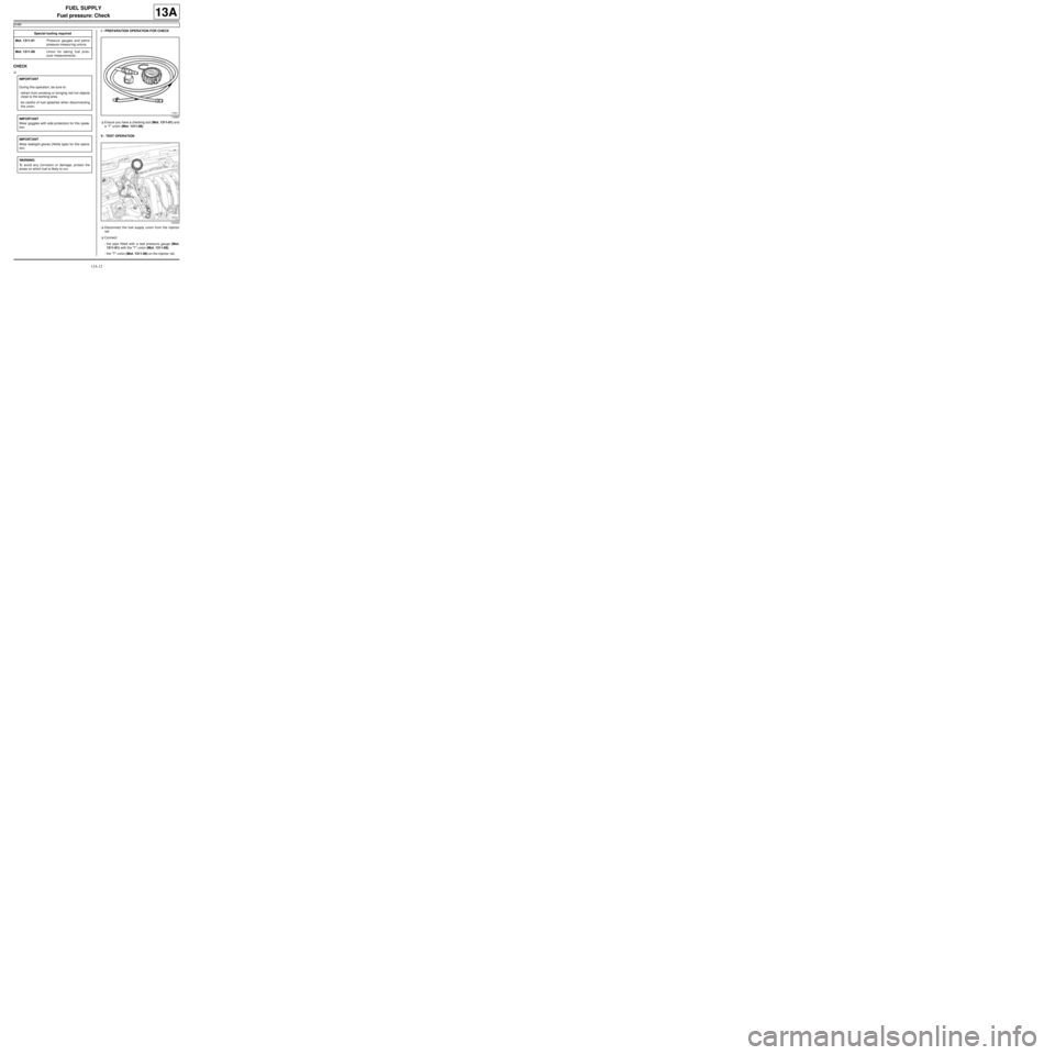
aEnsure you have a checking tool (Mot. 1311-01) and
a “T” union (Mot. 1311-08).
II - TEST OPERATION
aDisconnect the fuel supply union from the injector
rail.
aConnect:
-the pipe fitted with a test pressure gauge (Mot.
1311-01) with the "T" union (Mot. 1311-08),
-the "T" union (Mot. 1311-08) on the injector rail, Special tooling required
Mot. 1311-01Pressure gauges and petrol
pressure measur ing unions.
Mot. 1311-08Union for taking fuel pres-
sure measurements .
IMPORTANT
During this operation, be sure to:
-refrain from smoking or bringing red hot objects
close to the working area,
-be careful of fuel splashes when disconnecting
the union.
IMPORTANT
Wear goggles with side protectors for this opera-
tion.
IMPORTANT
Wear leaktight gloves (Nitrile type) for this opera-
tion.
WARNING
To avoid any corrosion or damage, protect the
areas on which fuel is likely to run.
116887
132333
Page 356 of 652
13A-13
FUEL SUPPLY
Fuel pressure: Check
K4M
13A
-the injector rail fuel supply union to the "T" union
(Mot. 1311-08).
aStart the engine.
aRecord the pressure; this should be constant at 3.5
bar.
aSwitch off the engine.
III - FINAL OPERATION
aDisconnect the "T" union (Mot. 1311-08) from the in-
jector rail.
aConnect the fuel supply pipe union on the injector
rail.Note:
It may take a few seconds to obtain a correct
injector rail pressure reading.
Page 360 of 652
13A-17
FUEL SUPPLY
Fuel flow: Check
K4M
13A
I - PREPARATION OPERATION FOR CHECK
aEnsure you have a checking tool (Mot. 1311-01) and
a “T” union (Mot. 1311-08).
aAssemble the long hose of the test tool (Mot. 1311-
01) and the "T" union (Mot. 1311-08).
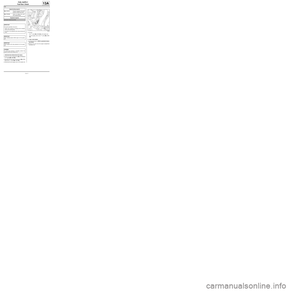
aDisconnect the fuel supply union on the injector rail.aConnect:
-the "T" union (Mot. 1311-08) on the injector rail,
-the fuel supply union to the "T" union (Mot. 1311-
08).
II - FUEL FLOW CHECK
aImmerse the hose in a 2000 ml graduated measur-
ing cylinder.
aRemove the cover from the engine compartment
connection unit. Special tooling required
Mot. 1311-01Pressure gauges and petrol
pressure measur ing unions.
Mot. 1311-08Union for taking fuel pres-
sure measurements .
Equipment required
graduated measuring cylinder
IMPORTANT
During this oper ation, be sure to:
-refrain from smoking or bringing red hot objects
close to the working area,
-be careful of fuel splashes when disconnecting the
union.
IMPORTANT
Wear leaktight gloves (Nitrile type) for this opera-
tion.
IMPORTANT
Wear goggles with side protectors for this opera-
tion.
WARNING
To avoid any corrosion or damage, protect the
areas on which fuel is likely to run.
132334
Page 361 of 652
13A-18
FUEL SUPPLY
Fuel flow: Check
K4M
13A
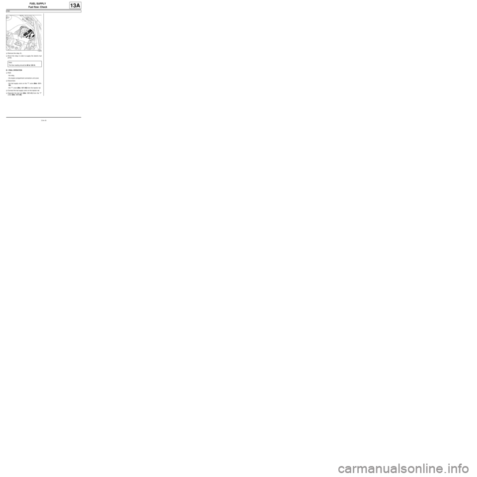
aRemove the relay (1) .
aShunt the relay in order to supply the electric fuel
pump.
III - FINAL OPERATION
aRefit:
-the relay,
-the engine compartment connection unit cover.
aDisconnect:
-the fuel supply union on the "T" union (Mot. 1311-
08),
-the "T" union (Mot. 1311-08) from the injector rail.
aConnect the fuel supply union on the injector rail.
aSeparate the test tool (Mot. 1311-01) from the "T"
union (Mot. 1311-08).
119373
Note:
The flow reading should be 80 to 120 l/h.
Page 422 of 652
14A-4
ANTIPOLLUTION
Fuel vapour absorber: Removal - Refitting
D4F or D7F or K4M, and TECHNICAL REG: GERMANY or TECHNICAL REG: AUSTRIA or TECHNICAL REG:
BALKANS or TECHNICAL-LEGISLATIVE BELGIUM or TECHNICAL REG: BOSNIA or TECHNICAL REG:
CYPRUS-MALTA or CZECH REP AND SLOVAKIA or TECHNICAL REG: DENMARK or TECHNICAL REG: DOM
(FRENCH OVERSEAS SUBDIVISION) or TECHNICAL REG: SPAIN or TECHNICAL REG: FINLAND or
TECHNICAL REG: FRANCE or TECHNICAL REG: GREAT BRITAIN or TECHNICAL REG: GREECE or
TECHNICAL-LEGISLATIVE HOLLAND or TECHNICAL REG: HUNGARY or TECHNICAL REG: IRELAND or
TECHNICAL REG: ICELAND or TECHNICAL REG: ISRAEL or TECHNICAL REG: ITALY or TECHNICAL REG:
JAPAN or TECHNICAL REG: NORTH or TECHNICAL REG: NORWAY or TECHNICAL REG: POLAND or
TECHNICAL REG: PORTUGAL or TECHNICAL REG: SLOVENIA or TECHNICAL REG: SWEDEN or TECHNICAL
REG: SWITZERLAND or TECHNICAL REG: TOM (FRENCH OVERSEAS TERRITORIES)
14A
REMOVAL
I - REMOVAL PREPARATION OPERATION
aPosition the vehicle on a two-post lift (see Vehicle:
Towing and lifting) (02A, Lifting equipment).
aDisconnect the battery (see Battery: Removal - Re-
fitting) (80A, Battery).
II - REMOVAL OPERATION
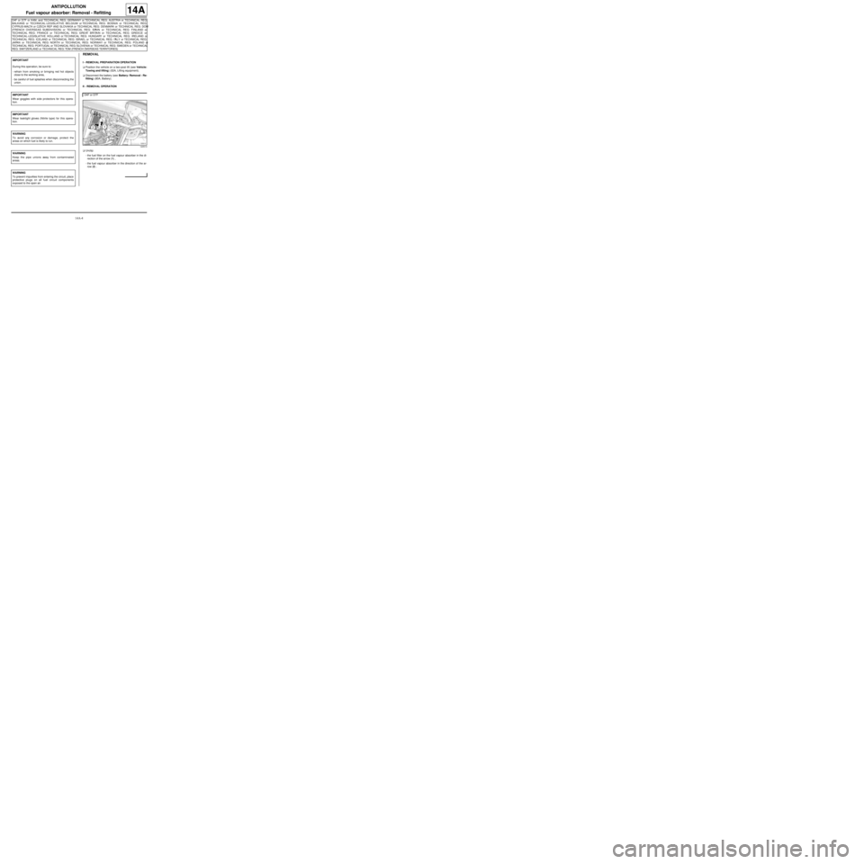
aUnclip:
-the fuel filter on the fuel vapour absorber in the di-
rection of the arrow (1) ,
-the fuel vapour absorber in the direction of the ar-
row (2) . IMPORTANT
During this oper ation, be sure to:
-refrain from smoking or bringing red hot objects
close to the working area,
-be careful of fuel splashes when disconnecting the
union.
IMPORTANT
Wear goggles with side protectors for this opera-
tion.
IMPORTANT
Wear leaktight gloves (Nitrile type) for this opera-
tion.
WARNING
To avoid any corrosion or damage, protect the
areas on which fuel is likely to run.
WARNING
Keep the pipe unions away from contaminated
areas.
WARNING
To prevent impurities from entering the circuit, place
protective plugs on all fuel circuit components
exposed to the open air.
D4F or D7F
120513
Page 423 of 652
14A-5
ANTIPOLLUTION
Fuel vapour absorber: Removal - Refitting
D4F or D7F or K4M, and TECHNICAL REG: GERMANY or TECHNICAL REG: AUSTRIA or TECHNICAL REG:
BALKANS or TECHNICAL-LEGISLATIVE BELGIUM or TECHNICAL REG: BOSNIA or TECHNICAL REG:
CYPRUS-MALTA or CZECH REP AND SLOVAKIA or TECHNICAL REG: DENMARK or TECHNICAL REG: DOM
(FRENCH OVERSEAS SUBDIVISION) or TECHNICAL REG: SPAIN or TECHNICAL REG: FINLAND or
TECHNICAL REG: FRANCE or TECHNICAL REG: GREAT BRITAIN or TECHNICAL REG: GREECE or
TECHNICAL-LEGISLATIVE HOLLAND or TECHNICAL REG: HUNGARY or TECHNICAL REG: IRELAND or
TECHNICAL REG: ICELAND or TECHNICAL REG: ISRAEL or TECHNICAL REG: ITALY or TECHNICAL REG:
JAPAN or TECHNICAL REG: NORTH or TECHNICAL REG: NORWAY or TECHNICAL REG: POLAND or
TECHNICAL REG: PORTUGAL or TECHNICAL REG: SLOVENIA or TECHNICAL REG: SWEDEN or TECHNICAL
REG: SWITZERLAND or TECHNICAL REG: TOM (FRENCH OVERSEAS TERRITORIES)
14A
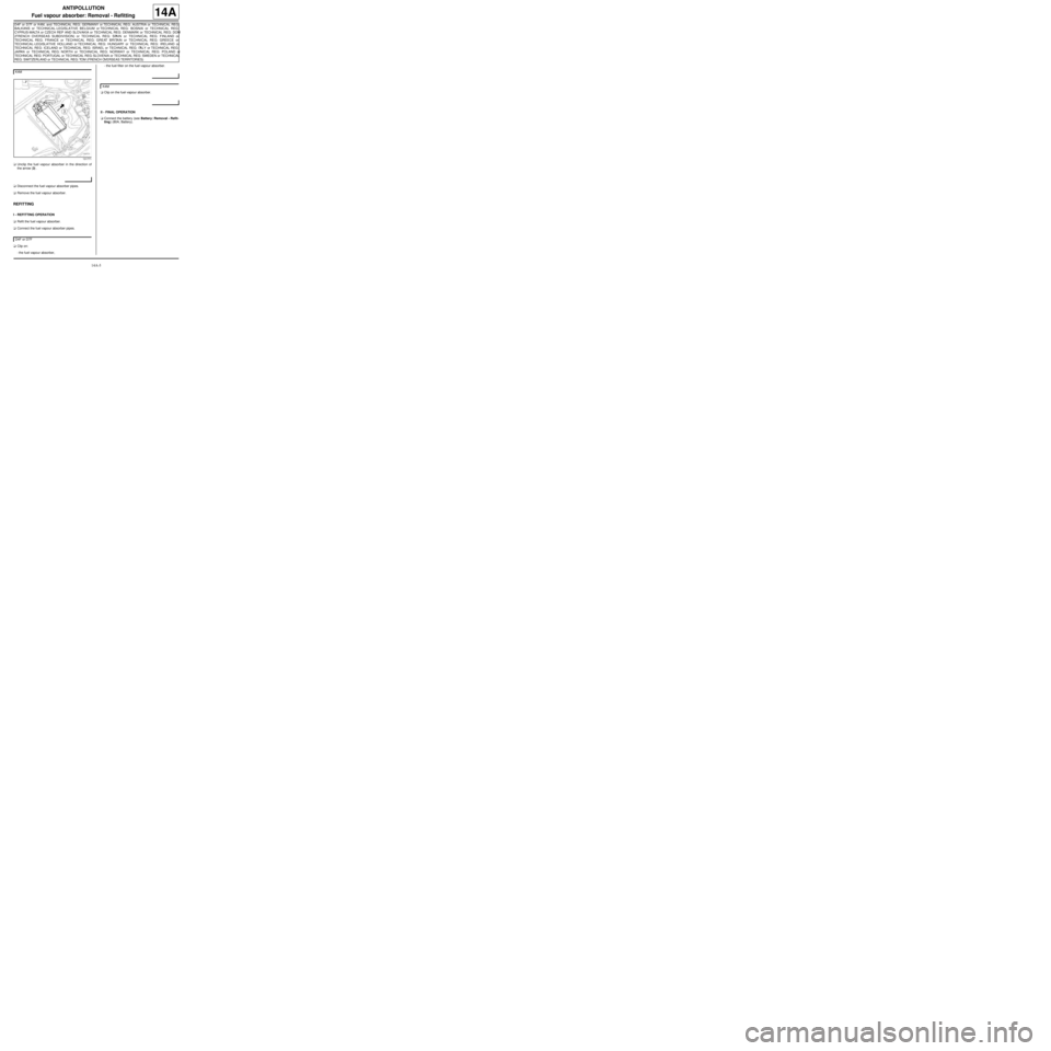
aUnclip the fuel vapour absorber in the direction of
the arrow (3) .
aDisconnect the fuel vapour absorber pipes.
aRemove the fuel vapour absorber.
REFITTING
I - REFITTING OPERATION
aRefit the fuel vapour absorber.
aConnect the fuel vapour absorber pipes.
aClip on:
-the fuel vapour absorber,-the fuel filter on the fuel vapour absorber.
aClip on the fuel vapour absorber.
II - FINAL OPERATION
aConnect the battery (see Battery: Removal - Refit-
ting) (80A, Battery). K4M
131771
D4F or D7F
K4M
Page 426 of 652
14A-8
ANTIPOLLUTION
Fuel vapour absorber bleed solenoid valve: Removal - Refitting
K4M
14A
REMOVAL
I - REMOVAL PREPARATION OPERATION
aDisconnect the battery (see Battery: Removal - Re-
fitting) (80A, Battery).
aRemove:
-the windscreen wiper arms (see Windscreen wip-
er arm: Removal - Refitting) (85A, Wiping -
Washing),
-the scuttle panel grille (see Scuttle panel grille:
Removal - Refitting) (56A, Exterior equipment),
-the scoop under the scuttle panel grille (see Scoop
under the scuttle panel grille: Removal - Refit-
ting) (56A, Exterior equipment).II - REMOVAL OPERATION
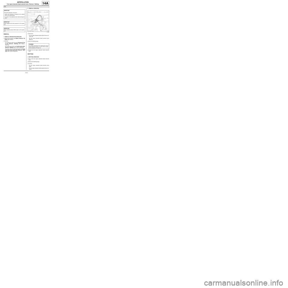
aDisconnect:
-the fuel vapour absorber bleed solenoid valve con-
nector (3) ,
-the fuel vapour absorber bleed solenoid valve
pipes (4) .
aInsert the blanking plugs.
aUnclip the fuel vapour absorber bleed solenoid
valve.
REFITTING
I - REFITTING OPERATION
aClip on the fuel vapour absorber bleed solenoid
valve.
aRemove the blanking plugs.
aConnect:
-the fuel vapour absorber bleed solenoid valve
pipes,
-the fuel vapour absorber bleed solenoid valve con-
nector. IMPORTANT
During this oper ation, be sure to:
-refrain from smoking or bringing red hot objects
close to the working area,
-be careful of fuel splashes when disconnecting the
union.
IMPORTANT
Wear goggles with side protectors for this opera-
tion.
IMPORTANT
Wear leaktight gloves (Nitrile type) for this opera-
tion.
131766
WARNING
To prevent impur ities from entering the circuit,
place protective plugs on all fuel circuit compo-
nents exposed to the open air.
Page 427 of 652
14A-9
ANTIPOLLUTION
Fuel vapour absorber bleed solenoid valve: Removal - Refitting
K4M
14A
II - FINAL OPERATION
aRefit:
-the scoop under the scuttle panel grille (see Scoop
under the scuttle panel grille: Removal - Refit-
ting) (56A, Exterior equipment),
-the scuttle panel grille (see Scuttle panel grille:
Removal - Refitting) (56A, Exterior equipment),
-the windscreen wiper arms (see Windscreen wip-
er arm: Removal - Refitting) (85A, Wiping -
Washing).
aConnect the battery (see Battery: Removal - Refit-
ting) (80A, Battery).