RENAULT TWINGO RS 2009 2.G Panelwork User Guide
TWINGO RS 2009 2.G
RENAULT
RENAULT
https://www.carmanualsonline.info/img/7/1724/w960_1724-0.png
RENAULT TWINGO RS 2009 2.G Panelwork User Guide
Trending: air condition, airbag, spare tire, open bonnet, brake light, headlight, door lock
Page 11 of 209
40A-6
GENERAL INFORMATION
Vehicle on repair bench: Description
C44
40A
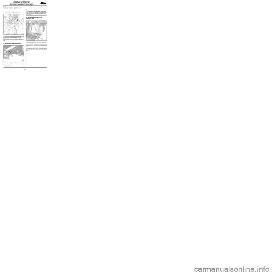
III - TRIM-SETTING MAIN REAR REFERENCE
POINTS
1 - Rear mechanical components in place
The jig supports the underside of the rear axle fork and
is centred in the rear axle bolt tapped hole (B) .
Use this situation for a frontal impact or a light rear im-
pact.
2 - Rear mechanical components removed
The jig rests under the rear side member and is cen-
tred on tapped hole (B) .
Use this situation for a rear impact with removal of the
mechanical components.IV - SECONDARY REAR TRIM-SETTING
REFERENCE POINT
The jig rests under the rear side member and is positio-
ned in the hole (J) .
Use this situation to confirm the trim-setting following a
frontal impact (e.g.: to replace a complete front half
unit).
It is used to confirm the vehicle trim setting in case of
doubt about the deformation of a main front reference
point.
120609
121746
Note:
If it is suspected that one of these points may be
deformed, use two additional points located in an
area not affected by the impact in order to confirm
trim-setting.
121748
Page 12 of 209
40A-7
GENERAL INFORMATION
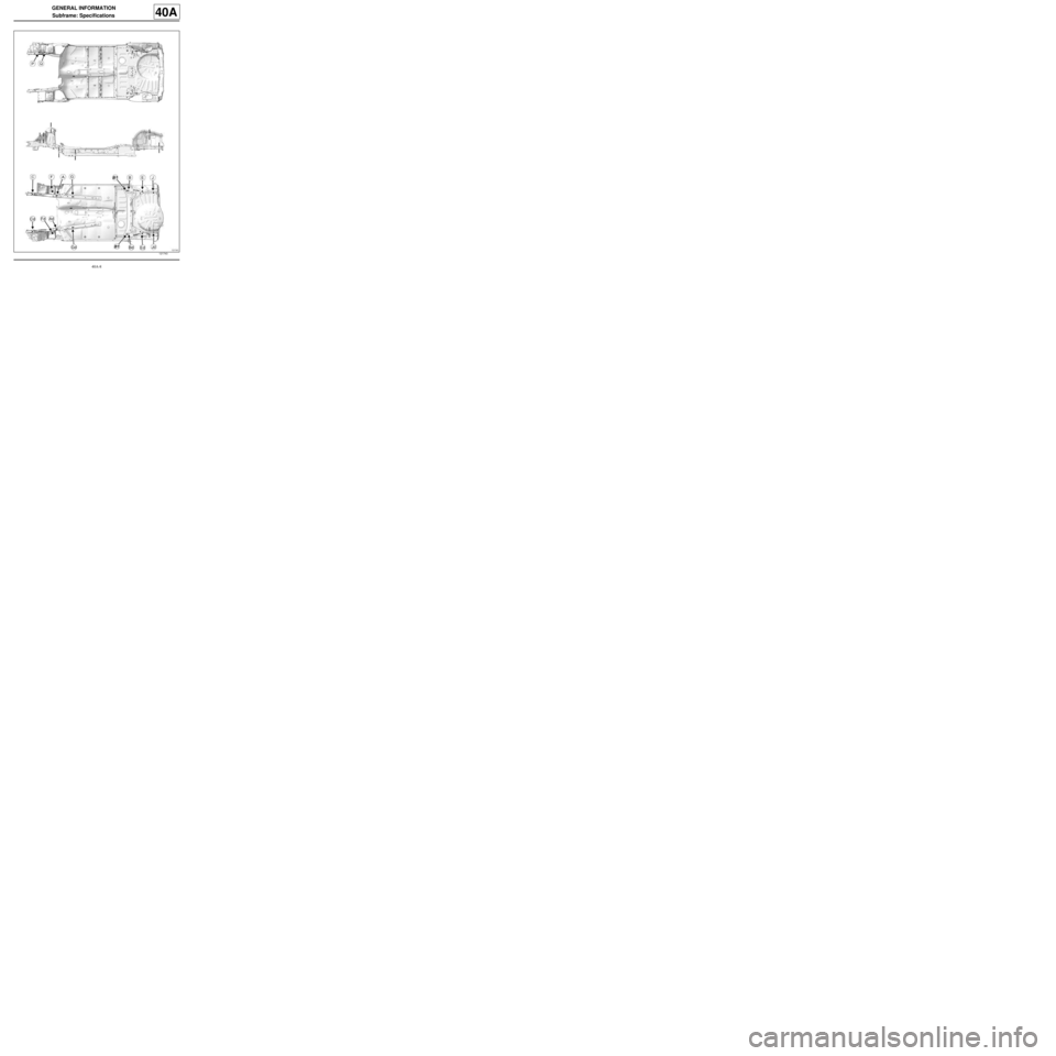
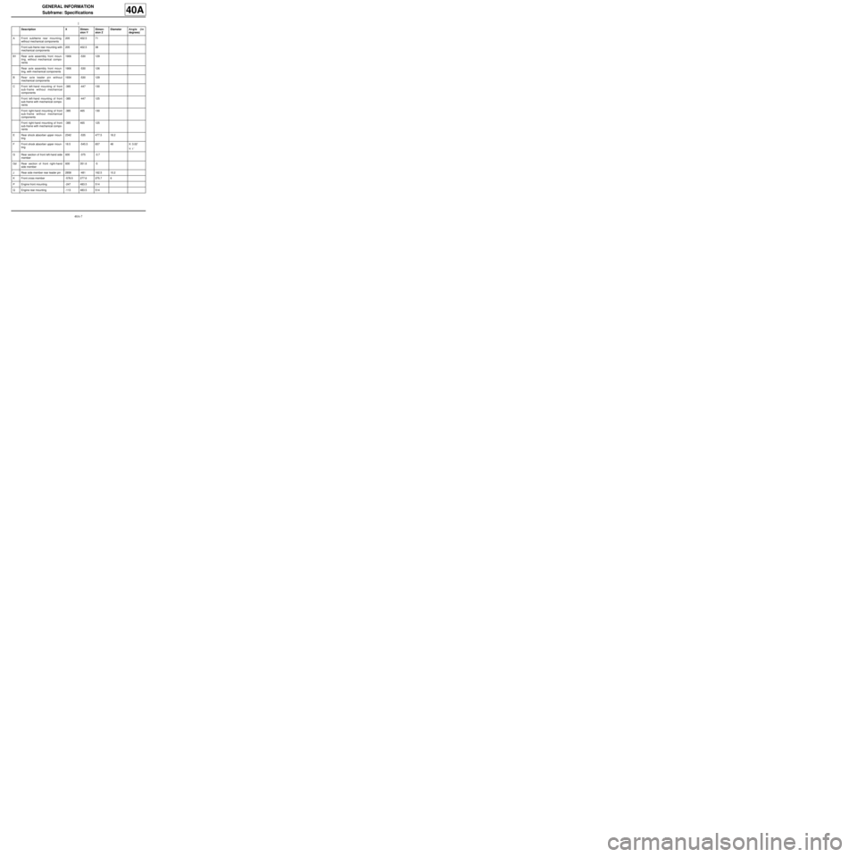
Subframe: Specifications
40A
Description X Dimen-
sion YDimen-
sion ZDiameterAngle (in
degrees)
AFront subframe rear mounting,
without mechanical components205 402.5 71
Front sub-frame rear mounting with
mechanical components205 402.5 38
B1Rear axle assembly front moun-
ting, without mechanical compo-
nents1906 -530 129
Rear axle assembly front moun-
ting, with mechanical components1906 -530 126
BRear axle leader pin without
mechanical components1934 -530 129
CFront left-hand mounting of front
sub-frame without mechanical
components-385 -447 130
Front left-hand mounting of front
sub-frame with mechanical compo-
nents-385 -447 125
Front right-hand mounting of front
sub-frame without mechanical
components-385 465 130
Front right-hand mounting of front
sub-frame with mechanical compo-
nents-385 465 125
ERear shock absorber upper moun-
ting2342 -535 477.5 18.2
FFront shock absorber upper moun-
ting18.5 -545.5 657 48 X: 3.02˚
Y: 1˚
GRear section of front left-hand side
member600 -375 -3.7
GdRear section of front right-hand
side member600 351.6 -5
JRear side member rear leader pin 2858 -481 162.5 10.2
KFront cross member -578.5 277.6 275.7 6
PEngine front mounting -247 483.5 514
QEngine rear mounting -113 483.5 514
Page 13 of 209
40A-8
GENERAL INFORMATION
Subframe: Specifications
40A
121743
Page 14 of 209
40A-9
GENERAL INFORMATION
Hollow section inserts: List and location of components40A
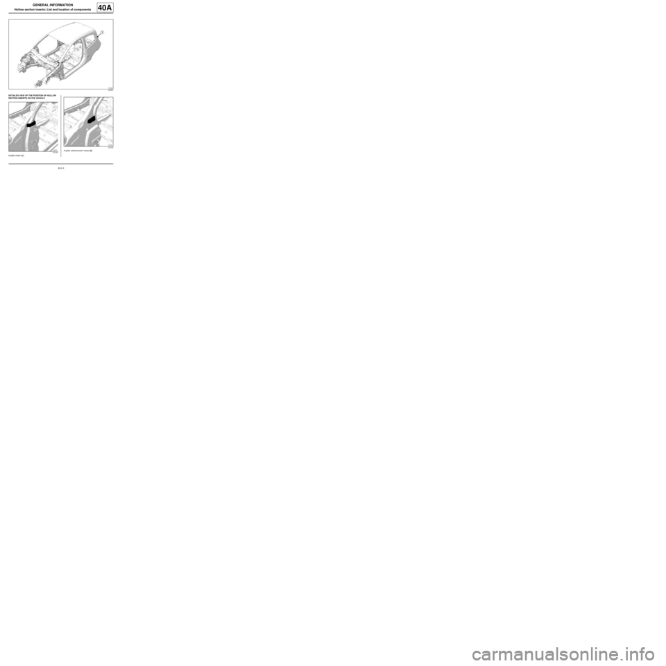
DETAILED VIEW OF THE POSITION OF HOLLOW
SECTION INSERTS ON THE VEHICLE
A-pillar insert (1) .A-pillar reinforcement insert (2) .
121241
121243
121244
Page 15 of 209
40A-10
GENERAL INFORMATION
Hollow section inserts: List and location of components40A
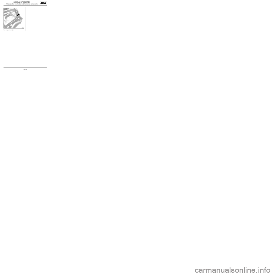
Rear wing panel insert (3) .
121242
Page 16 of 209
40A-11
GENERAL INFORMATION
Hollow section inserts: Precautions for the repair
40A
The expanding inserts ensure that the vehicle cavities
are sealed and soundproofed. They react to the tempe-
rature when the bodywork is immersed in the catapho-
retic bath at the factory. These conditions cannot be
reproduced on the bodywork.
As inserts are not recoverable, always replace expan-
ding inserts.
The inserts supplied by the Parts Department are
identical to the original parts.
To obtain the same sealing and soundproofing proper-
ties, carry out the following operations:
-clean the bonding surfaces with heptane,
-if necessary, block the holes in the insert using pieces
cut from a soundproofing pad.
-apply a bead of preformed trim sealing mastic around
and inside the insert holes,
-fit the insert by compressing the mastic.
In some cases, it is possible to replace the accessible
part of the insert only, which must be cut out of the re-
placement part.WARNING
Do not refit the part after compressing the bead.
When EGW welding, protect the inserts from spat-
ter and heat dispersion.
For example, use a heat shield.
Page 17 of 209
40A-12
GENERAL INFORMATION
Earths on body: List and location of components
40A
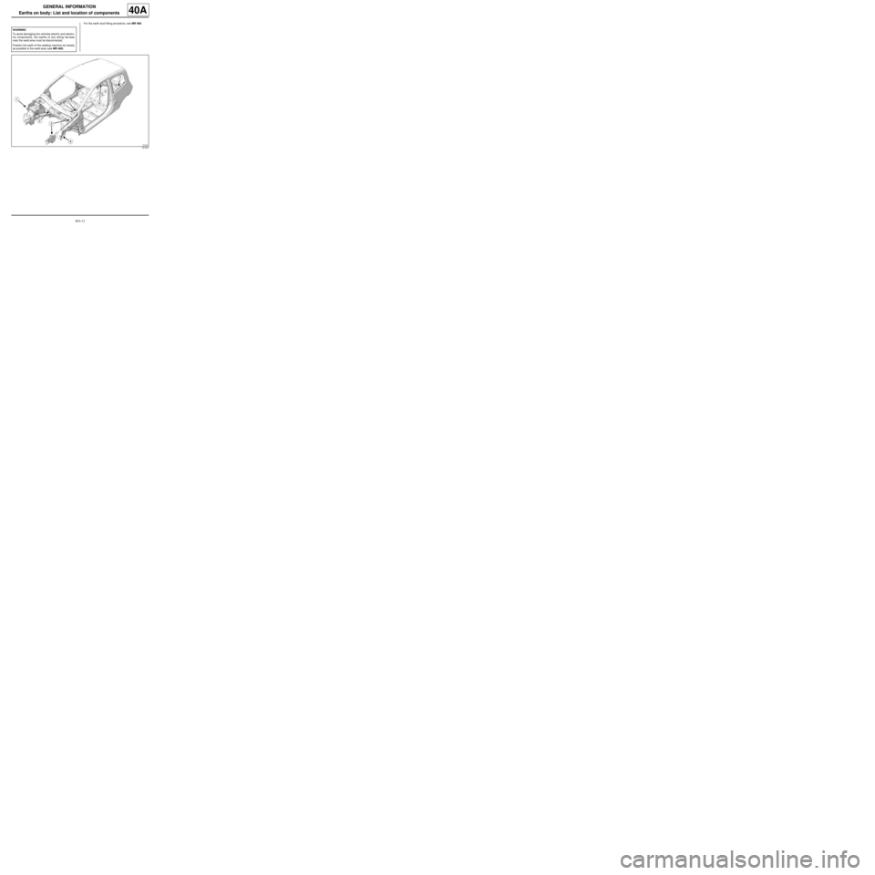
For the earth stud fitting procedure, see MR 400.
WARNING
To avoid damaging the vehicles electric and electro-
nic components, the earths of any wiring harness
near the weld area must be disconnected.
Position the earth of the welding machine as closely
as possible to the weld area (see MR 400).
121241
Page 18 of 209
40A-13
GENERAL INFORMATION
Earths on body: List and location of components
40A
DETAILED VIEW OF THE POSITION OF EARTHS
ON THE VEHICLE
Earth stud on the front right-hand wing lower bracket
(1) .
Earth stud on the bulkhead (2) .Earth stud on the front left-hand side member and scu-
ttle side panel (3) .
Earth stud on the front left-hand wing lower bracket (4)
.
121247
121246
121245
121248
Page 19 of 209
40A-14
GENERAL INFORMATION
Earths on body: List and location of components
40A
Earth stud on the tunnel (5) .
Earth stud on the right-hand rear quarter lining (6) .Earth stud on the rear quarter lining (7) .
125408
121249121250
Page 20 of 209
40A-15
GENERAL INFORMATION
Vehicle structure, front section: Description
40A
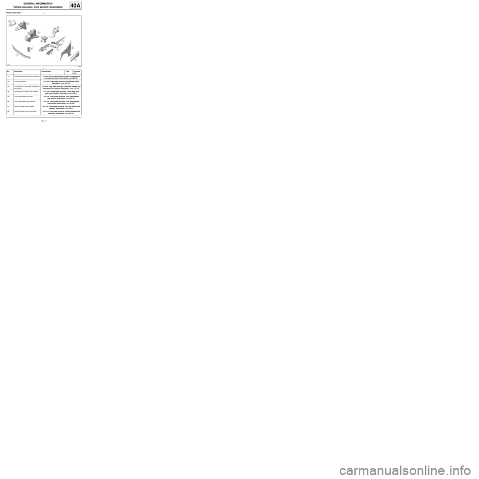
FRONT STRUCTURE
125409
No. Description Classification Type Thickness
(mm)
(1) Scuttle side panel upper reinforcement (see 42A, Front upper structure, Upper reinforcement
of scuttle side panel: Description, page 42A-19)
(2) Scuttle side panel (see 42A, Front upper structure, Scuttle side panel:
Description, page 42A-16)
(3) Front section of front side member clo-
sure panel (see 41A, Front lower structure, Front side member clo-
sure panel, front section: Description, page 41A-13)
(4) Centre floor front side cross member (see 41B, Centre lower structure, Centre floor front
side cross member: Description, page 41B-7)
(5) Front side member rear part (see 41A, Front lower structure, Front side member,
rear section: Description, page 41A-15)
(6) Front side member front section (see 41A, Front lower structure, Front side member,
front section: Description, page 41A-8)
(7) front-end lower cross member (see 41A, Front lower structure, Front end lower cross
member: Description, page 41A-2)
(8) Front mounting of front sub-frame (see 41A, Front lower structure, Front subframe front
mounting: Description, page 41A-18)
Trending: instrument panel, brake, ESP, tailgate, gas type, warning, lock


