RENAULT TWINGO RS 2009 2.G Panelwork Owner's Guide
Manufacturer: RENAULT, Model Year: 2009, Model line: TWINGO RS, Model: RENAULT TWINGO RS 2009 2.GPages: 209
Page 31 of 209

40A-26
GENERAL INFORMATION
Structural components to be positioned on the repair bench: Description40A
The jig rests against the rear section of the side mem-
ber and is centred in the sub-frame rear mounting hole
(11) .
The jig is used for replacing a complete front half unit.
III - REAR AXLE ASSEMBLY FRONT MOUNTING
The jig supports the underneath of the rear axle as-
sembly mounting unit and is centred on threaded hole
(12) of the rear axle bearing mounting.
The jig is used for replacing a rear side member as-
sembly.IV - FRONT SUBFRAME FRONT MOUNTING
The jig supports the underneath of the front sub-frame
mounting and is centred on tapped hole (13) .
The jig is used to replace:
-a complete front side member,
-a front half unit. IMPORTANT
This point contributes to ensuring the front axle
geometry. This point aligns the subframe of the
front axle in relation to the body. This point has a
direct influence on all of the front axle angles.
121746
IMPORTANT
These points contribute to ensuring the alignment
of the rear axle in relation to the body. These points
have a direct influence on all of the path angles of
the vehicle.
121752
IMPORTANT
This point contributes to ensuring the front axle
geometry. This point aligns the subframe of the
front axle in relation to the body. This point has a
direct influence on all of the front axle angles.
Page 32 of 209
40A-27
GENERAL INFORMATION
Structural components to be positioned on the repair bench: Description40A
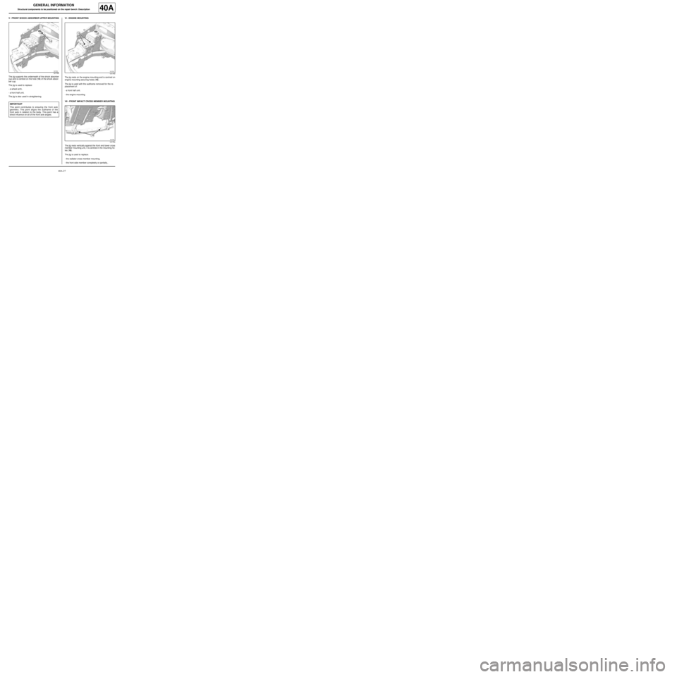
V - FRONT SHOCK ABSORBER UPPER MOUNTING
The jig supports the underneath of the shock absorber
cup and is centred on the hole (14) of the shock absor-
ber cup.
The jig is used to replace:
-a wheel arch,
-a front half unit.
The jig is also used in straightening.VI - ENGINE MOUNTING
The jig rests on the engine mounting and is centred on
engine mounting securing holes (15) .
The jig is used with the subframe removed for the re-
placement of:
-a front half unit.
-the engine mounting.
VII - FRONT IMPACT CROSS MEMBER MOUNTING
The jig rests vertically against the front end lower cross
member mounting unit, it is centred in the mounting ho-
les (16) .
The jig is used to replace:
-the radiator cross member mounting,
-the front side member completely or partially,.
121753
IMPORTANT
This point contributes to ensuring the front axle
geometry. This point aligns the subframe of the
front axle in relation to the body. This point has a
direct influence on all of the front axle angles.
121753
121754
Page 33 of 209
40A-28
GENERAL INFORMATION
Structural components to be positioned on the repair bench: Description40A
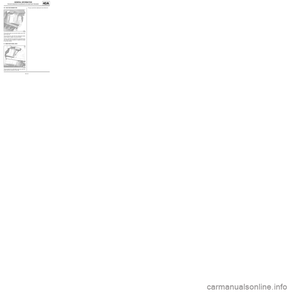
VIII - REAR SIDE MEMBER END
The jig rests under the rear side member and is cen-
tred in hole (17) .
The jig should be used with the mechanical compo-
nents in place to realign a rear side member.
The jig is used with the mechanical components remo-
ved, under the same conditions, to replace the comple-
te rear side member.
IX - INNER REAR WHEEL ARCH
The jig supports the underneath of the rear shock ab-
sorber cup and is centred on hole (18) .The jig is used when replacing the rear wheel arch.
121748
121749
Page 34 of 209
40A-29
GENERAL INFORMATION
Structural bodywork documentation: Description
40A
I - - CLASSIFYING INFORMATION
This information is classified in two complementary do-
cuments:
1 - Vehicle structure bodywork repair procedures
(MR of the vehicle concerned)
This document comprises two sections:
a - Section 0:
This section does not contain repair methods, it only
contains description information; it consists of several
subsections:
-01C Vehicle bodywork specifications,
-02A Lifting equipment,
-02B Bodywork innovations,
-03B Collision,
-04B Consumables - Products,
-04E Painting,
-05B Bodywork equipment and tooling.
b - Section 4:
This section consists of several subsections:
-40A General information,
-41A Lower front structure,
-41B Lower central structure,
-41C Lower side structure,
-41D Lower rear structure,
-42A Upper front structure,
-43A Upper side structure,
-44A Upper rear structure,
-45A Top of body,
-47A Side opening elements,
-48A Non-side opening elements.
These subsections are linked to the Replacement
Parts Catalogue and contain two types of information:
-Section 1: General description. This section con-
tains information relating to generic structural spare
parts and to their design. This information may be the
same for several vehicles.
-Section 2: Description, Removal - Refitting, Strip -
Rebuild and Adjustment. This section contains in-
formation relating to structural spare parts and the
special features of the vehicle concerned.2 - Fundamentals of the structure bodywork repair
(MR 400)
This document comprises two sections:
a - Section 0:
this section consists of several subsections:
-04F Bodywork products and mountings
-05B Bodywork equipment and tooling
b - Section 4:
This section contains information on the basic opera-
ting ranges which concern the bodyshop technician.
this section consists of several subsections:
-40A General information
-40B Electrical resistance welded connections
-40C Gas metal arc welded connections (GMAW)
-40D Laser welded connections
-40E Partial replacement connections
-04F Bonded connections
-40G Riveted connections
-40H Screw connections
-40J Protective devices Note:
Always read both parts in order to have all the
necessary information to repair the vehicle.
Page 35 of 209
40A-30
GENERAL INFORMATION
Structural bodywork documentation: Description
40A
II - INFORMATION SEARCH
Questions Answers
Features of specific tools to repair a given vehicle.Refer firstly to section 0 of the Vehicle MR then refer
to the « special tooling catalogue » or the « garage
equipment catalogue » .
Features of specific products to repair a given vehicle. Firstly refer to section 0 of the Vehicle MR then refer
to the « IXELL product catalogue » .
Description and part number of a specific tool to
repair a giv en vehicle.Firstly refer to section 0 of the Vehicle MR.
Using a bodywork tool. Refer to subsection 40A of the Vehicle MR.
Information concerning the replacement parts of a
given vehicle regarding:
-the possibilities of replacement with the position on
vehicle,
-an adaptation before the assembly,
-a cutting place with the special notes on this cut,
-special notes on r ight-left symmetry.
-special features of the version or equipment.Refer to the subsection which corresponds to the part
concerned: 41 to 48 of the Vehicle MR.
Information concerning the spare parts of a given
vehicle, the composition and the specifications of
each par t it contains.Firstly refer to the parts description exploded view in
subsection 40 of the Vehicle MR.
If this is detailed in the document, refer to subsections
41 to 48 of the Vehicle MR which corresponds to the
par t concerned.
If this does not appear in the description, refer to sub-
section 41 to 48 for the part in the next level up.
Information concerning:
-details of panel overlap on a joint,
-a procedure and an operational mode relating to a
new type of assembly in Renault,
-a method for using a tool or a new product which is
unfamiliar in Renault.Refer to the subsection which corresponds to the part
concerned: 41 to 48 of the Vehicle MR then subsec-
tion 40 of Vehicle MR 400.
Towing and raising a vehicle after an accident. Firstly refer to subsection 02A of the Vehicle MR then
the equipment catalogue.
Combination of impacts to repair a given vehicle. Refer to subsection 03B of the Vehicle MR.
Fault finding on an impact for a given vehicle.Firstly refer to subsection 03B of the Vehicle MR or
MR 400.
Page 36 of 209
40A-31
GENERAL INFORMATION
Structural bodywork documentation: Description
40A
III - SYMBOLS FOR STRUCTURE REPAIR
PROCEDURES
You will find below the detailed explanations of all the
symbols used in the structure bodywork methods.
At the top of each DU you will find a reminder of these
different components:
-the tightening torques,
-the specific tools.
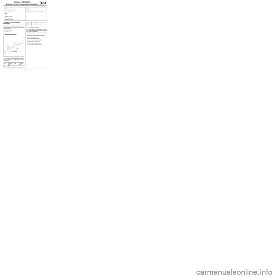
1 - Specifications of spare parts
When a spare part consists of several parts, a table in-
dicates the components of the spare part with notes on
the illustration.2 - In the event of replacement
Only on illustrations of replacement parts, the bold
lines indicate the possible cuts that can be made in the
case of a partial replacement.
A list indicates the name and the marks that delimit the
replacement
The options for replacing this part are as follows:
-complete replacement A-D-F,
-front end partial replacement A-C,
-front section partial replacement A-D-E,
-partial replacement under door B-C,
-rear section partial replacement C-D-F,
-rear end section partial replacement E-F. Logic of impact fault finding. See MR 400.
General instr uctions for:
-repair,
-safety,
-preparing a vehicle,
-tool classification,
-precautions for repair.Refer to section 0 of the Vehicle MR or MR 400. Questions Answers
136096
No. Descrip-
tionType Thickness
(mm)
(1)
(2)
(3)
Page 37 of 209
40A-32
GENERAL INFORMATION
Structural bodywork documentation: Description
40A
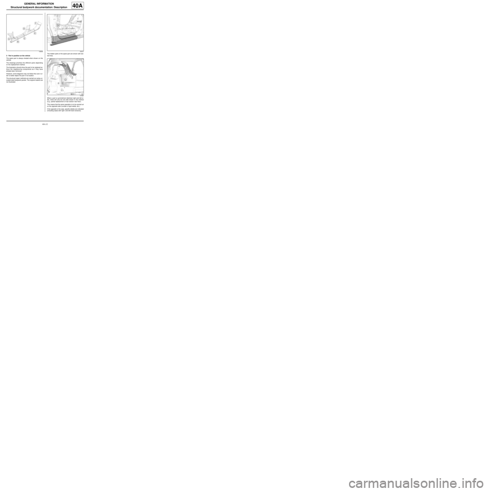
3 - Part in position on the vehicle
The spare part is always shaded when shown on the
vehicle.
The drawings prioritise the different parts depending
on the replacement method.
The illustration should show the part to be replaced wi-
thout the neighbouring components as if they have
already been removed.
However, some diagrams may not follow this rule in or-
der to better depict the part in its location.
The structural repair methods are carried out using un-
coated steel bodywork panels. The original mastics are
not illustrated.The hidden parts of the spare part are shown with dot-
ted lines.
When a part is symmetrical (identical right and left si-
de), there will only be one side shown in the method
(e.g.: partial replacement of rear section rear floor).
This means that the same operation is to be carried out
on the opposite side (number of spot welds, etc.).
If the opposite is the case, specific details are indicated
(including cases with right- and left-hand versions).
136098136107
137597
Page 38 of 209

40A-33
GENERAL INFORMATION
Structural bodywork documentation: Description
40A
4 - Symbols for detailed views
The detailed views define the space between the part
to replace and the vehicle structure.
The mark (A) designates the viewing direction of the
detailed view for proper orientation of the associated
detailed view.
Detailed view A
5 - Symbols for opening element adjustments
Different symbols indicate the possibilities for adjust-
mentThe mountings are shaded.
6 - Symbols for adhesives and mastics
A shaded band represents the path of a bead of adhe-
sive or mastic.
136108
136100
109496
137603
Page 39 of 209
40A-34
GENERAL INFORMATION
Structural bodywork documentation: Description
40A
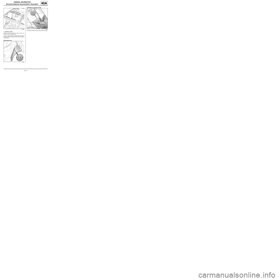
7 - Symbols for welds
Different symbols represent the type of weld to be
made if it is not an original weld.
In case of superimposed or joggle welds, the type of
weld to be made is indicated in the text accompanying
the illustration.
Superimposed weldCombination of two types of welds
If two types of welds are used, points delimit the areas.
136359
137559137242
Page 40 of 209
41A-1
FRONT LOWER STRUCTURE
Front end lower cross member: General description
41A
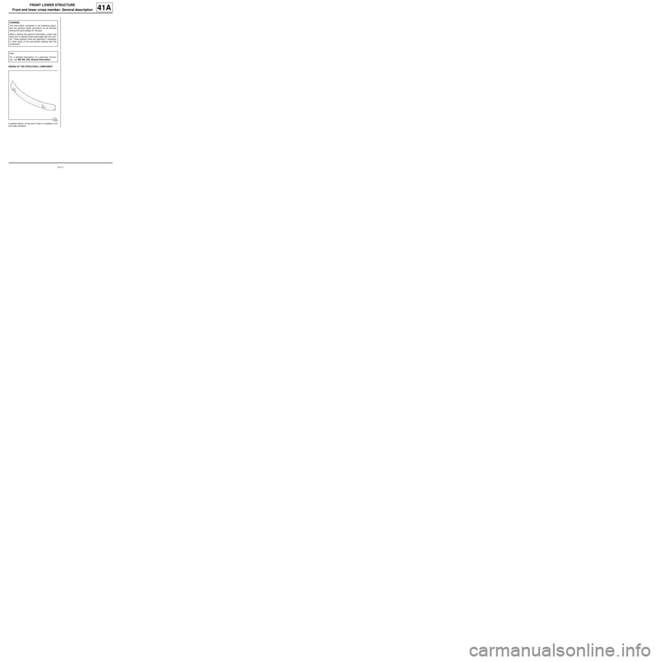
DESIGN OF THE STRUCTURAL COMPONENT
A special feature of this part is that it is welded to the
front side members.WARNING
The information contained in the following descri-
bes the general repair procedure for all vehicles
having the same design for this part.
Before reading this general information, check that
there are no special notes associated with this vehi-
cle. These special notes are specified if necessary
in other parts of the sub-section dealing with the
component.
Note:
For a detailed description of a particular connec-
tion, see MR 400, 40A, General Information.
110524