RENAULT TWINGO RS 2009 2.G Sequential Transmission Repair Manual
Manufacturer: RENAULT, Model Year: 2009, Model line: TWINGO RS, Model: RENAULT TWINGO RS 2009 2.GPages: 138
Page 51 of 138
21B-51
MR-413-X44-21B000$413.mif
V2
SEQUENTIAL GEARBOX
Fault finding - Interpretation of faults
Vdiag No.: 04
21B
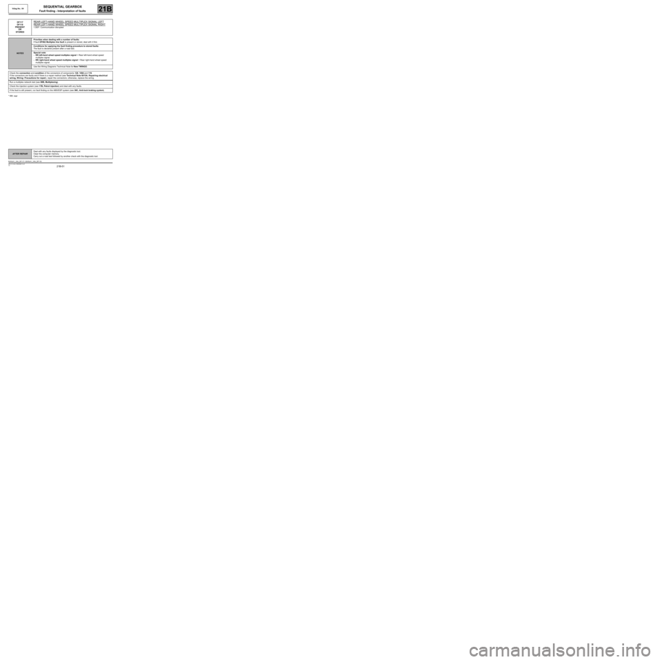
* RR: rearDF117
DF118
PRESENT
OR
STORED
REAR LEFT-HAND WHEEL SPEED MULTIPLEX SIGNAL LEFT
REAR LEFT-HAND WHEEL SPEED MULTIPLEX SIGNAL RIGHT
1.DEF: Communication disrupted
NOTESPriorities when dealing with a number of faults:
If fault DF062 Multiplex line fault is present or stored, deal with it first.
Conditions for applying the fault finding procedure to stored faults:
The fault is declared present after a road test.
Special note:
–RR left-hand wheel speed multiplex signal = Rear left-hand wheel speed
multiplex signal.
–RR right-hand wheel speed multiplex signal = Rear right-hand wheel speed
multiplex signal.
Use the Wiring Diagrams Technical Note for New TWINGO.
Check the connection and condition of the connectors of components 120, 1094 and 119.
If the connectors are faulty and if there is a repair method (see Technical Note 6015A, Repairing electrical
wiring, W iring: Precautions for repair), repair the connectors; otherwise, replace the wiring.
Run a multiplex network test (see 88B, Multiplexing).
Check the injection system (see 17B, Petrol injection) and deal with any faults.
If the fault is still present, run fault finding on the ABS/ESP system (see 38C, Anti-lock braking system).
AFTER REPAIRDeal with any faults displayed by the diagnostic tool.
Clear the computer memory.
Carry out a road test followed by another check with the diagnostic tool.
BVRJH1_V04_DF117 / BVRJH1_V04_DF118
Page 52 of 138
21B-52
MR-413-X44-21B000$413.mif
V2
SEQUENTIAL GEARBOX
Fault finding - Interpretation of faults
Vdiag No.: 04
21B
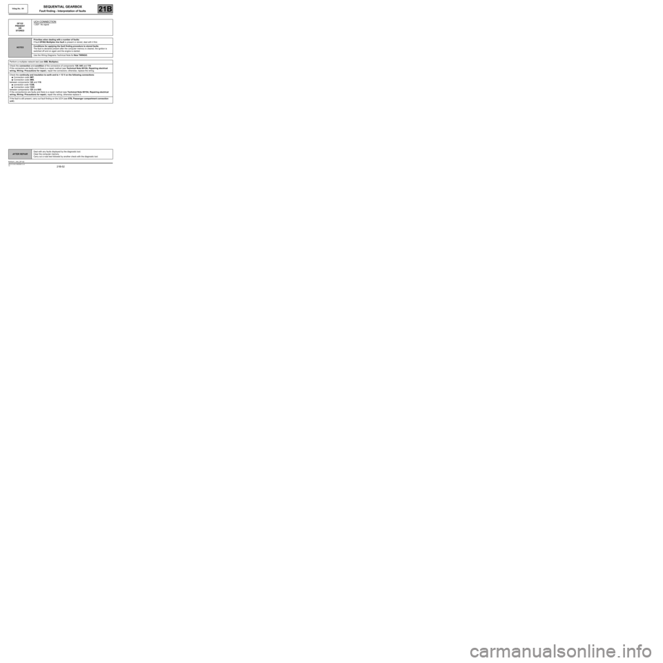
DF122
PRESENT
OR
STOREDUCH CONNECTION
1.DEF: No signal
NOTESPriorities when dealing with a number of faults:
If fault DF062 Multiplex line fault is present or stored, deal with it first.
Conditions for applying the fault finding procedure to stored faults:
The fault is declared present after the computer memory is cleared, the ignition is
switched off and on again and the engine is started.
Use the Wiring Diagrams Technical Note for New TWINGO.
Perform a multiplex network test (see 88B, Multiplex).
Check the connection and condition of the connectors of components 120, 645 and 119.
If the connectors are faulty and if there is a repair method (see Technical Note 6015A, Repairing electrical
wiring, W iring: Precautions for repair), repair the connectors; otherwise, replace the wiring.
Check the continuity and insulation to earth and to + 12 V on the following connections:
●Connection code 3MT,
●Connection code 3MS,
between components 120 and 119.
●connection code 133B,
●Connection code 133C,
between components 120 and 645.
If the connection(s) are faulty and there is a repair method (see Technical Note 6015A, Repairing electrical
wiring, W iring: Precautions for repair), repair the wiring, otherwise replace it.
If the fault is still present, carry out fault finding on the UCH (see 87B, Passenger compartment connection
unit).
AFTER REPAIRDeal with any faults displayed by the diagnostic tool.
Clear the computer memory.
Carry out a road test followed by another check with the diagnostic tool.
BVRJH1_V04_DF122
Page 53 of 138
21B-53
MR-413-X44-21B000$472.mif
V2
21B
SEQUENTIAL GEARBOX
Fault finding - Interpretation of faults
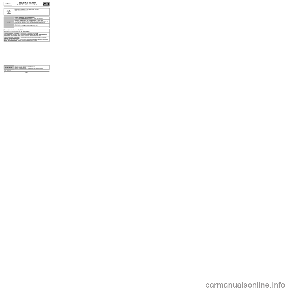
DF144
PRESENT
OR
STOREDCOOLANT TEMPERATURE MULTIPLEX SIGNAL
1.DEF : Communication disrupted
NOTESPriorities when dealing with a number of faults:
If fault DF062 Multiplex line fault is present or stored, deal with it first.
Conditions for applying the fault finding procedure to stored faults:
The fault is declared present after the computer fault memory has been cleared, the
ignition has been switched off and on again and the engine has been started.
Special note:
Default value PR145 Engine coolant temperature = 20 ˚C
Use the Wiring Diagrams Technical Note for New TWINGO.
Run a multiplex network test (see 88B, Multiplex).
Run a check of the injection system (see 17B, Petrol injection).
Check the connection and condition of the connectors of components 120 and 119.
If the connectors are faulty and if there is a repair method (see Technical Note 6015A, Repairing electrical
wiring, W iring: Precautions for repair), repair the connectors; otherwise, replace the wiring.
Check the connection and condition of the coolant temperature sensor connector (component code 244)
integrated with the injection system.
If the connector is faulty and there is a repair procedure (see Technical Note 6015A, Electrical wiring repair,
Wiring: Precautions for repair), repair the connector, otherwise replace the wiring.
AFTER REPAIRDeal with any faults detected by the diagnostic tool.
Clear the computer memory.
Carry out a road test followed by another check with the diagnostic tool.
BVRJH1_V04_DF144
Vdiag No: 04
MR-413-X44-21B000$472.mif
Page 54 of 138
21B-54
MR-413-X44-21B000$472.mif
V2
SEQUENTIAL GEARBOX
Fault finding - Interpretation of faults
Vdiag No: 04
21B
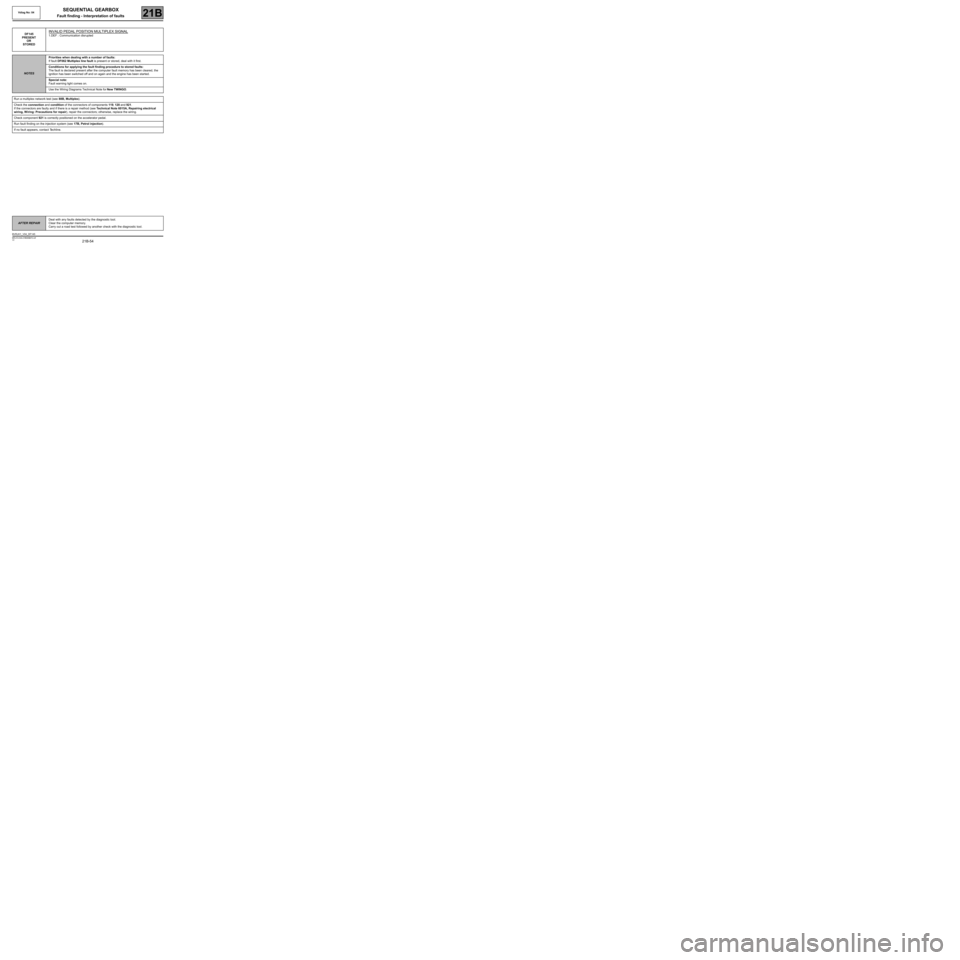
DF145
PRESENT
OR
STOREDINVALID PEDAL POSITION MULTIPLEX SIGNAL
1.DEF : Communication disrupted
NOTESPriorities when dealing with a number of faults:
If fault DF062 Multiplex line fault is present or stored, deal with it first.
Conditions for applying the fault finding procedure to stored faults:
The fault is declared present after the computer fault memory has been cleared, the
ignition has been switched off and on again and the engine has been started.
Special note:
Fault warning light comes on.
Use the Wiring Diagrams Technical Note for New TWINGO.
Run a multiplex network test (see 88B, Multiplex).
Check the connection and condition of the connectors of components 119, 120 and 921.
If the connectors are faulty and if there is a repair method (see Technical Note 6015A, Repairing electrical
wiring, W iring: Precautions for repair), repair the connectors; otherwise, replace the wiring.
Check component 921 is correctly positioned on the accelerator pedal.
Run fault finding on the injection system (see 17B, Petrol injection).
If no fault appears, contact Techline.
AFTER REPAIRDeal with any faults detected by the diagnostic tool.
Clear the computer memory.
Carry out a road test followed by another check with the diagnostic tool.
BVRJH1_V04_DF145
MR-413-X44-21B000$472.mif
Page 55 of 138
21B-55
MR-413-X44-21B000$472.mif
V2
SEQUENTIAL GEARBOX
Fault finding - Interpretation of faults
Vdiag No: 04
21B
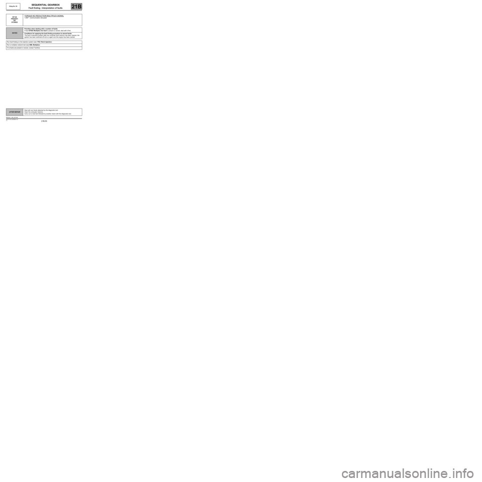
DF146
PRESENT
OR
STOREDTORQUE NO REDUCTION MULTIPLEX SIGNAL
1.DEF : Communication disrupted
NOTESPriorities when dealing with a number of faults:
If fault DF062 Multiplex line fault is present or stored, deal with it first.
Conditions for applying the fault finding procedure to stored faults:
The fault is declared present after the computer fault memory has been cleared, the
ignition has been switched off and on again and the engine has been started.
Run fault finding on the injection system (see 17B, Petrol injection).
Run a multiplex network test (see 88B, Multiplex).
If no faults are present or stored, contact Techline.
AFTER REPAIRDeal with any faults detected by the diagnostic tool.
Clear the computer memory.
Carry out a road test followed by another check with the diagnostic tool.
BVRJH1_V04_DF146
Page 56 of 138
21B-56
MR-413-X44-21B000$472.mif
V2
SEQUENTIAL GEARBOX
Fault finding - Interpretation of faults
Vdiag No: 04
21B
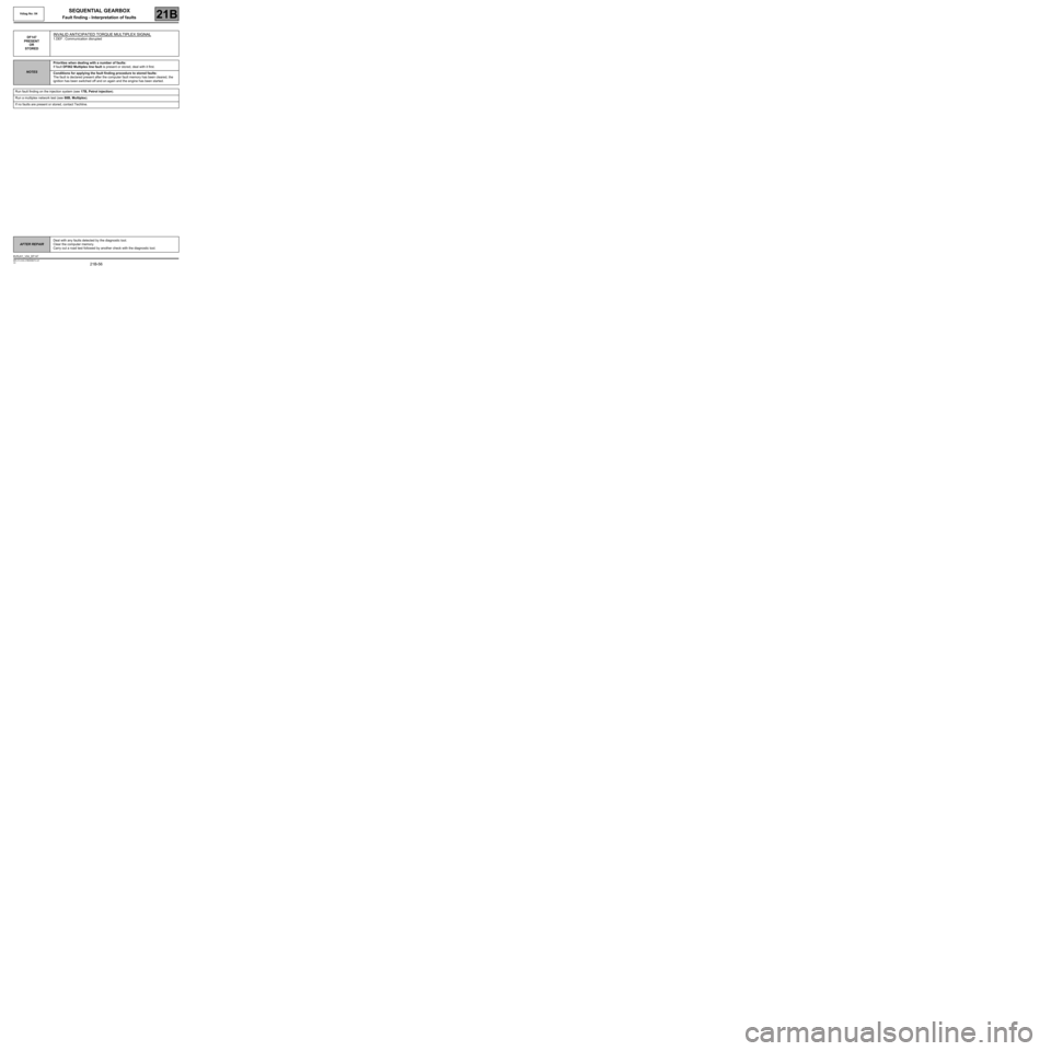
DF147
PRESENT
OR
STOREDINVALID ANTICIPATED TORQUE MULTIPLEX SIGNAL
1.DEF : Communication disrupted
NOTESPriorities when dealing with a number of faults:
If fault DF062 Multiplex line fault is present or stored, deal with it first.
Conditions for applying the fault finding procedure to stored faults:
The fault is declared present after the computer fault memory has been cleared, the
ignition has been switched off and on again and the engine has been started.
Run fault finding on the injection system (see 17B, Petrol injection).
Run a multiplex network test (see 88B, Multiplex).
If no faults are present or stored, contact Techline.
AFTER REPAIRDeal with any faults detected by the diagnostic tool.
Clear the computer memory.
Carry out a road test followed by another check with the diagnostic tool.
BVRJH1_V04_DF147
Page 57 of 138
21B-57
MR-413-X44-21B000$472.mif
V2
SEQUENTIAL GEARBOX
Fault finding - Interpretation of faults
Vdiag No: 04
21B
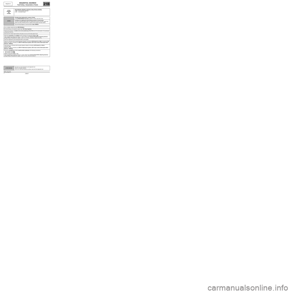
DF148
PRESENT
OR
STOREDSECONDARY BRAKE CONTACT MULTIPLEX SIGNAL
1.DEF : Communication disrupted
2.DEF : Inconsistent signal
NOTESPriorities when dealing with a number of faults:
If fault DF062 Multiplex line fault is present or stored, deal with it first.
Conditions for applying the fault finding procedure to stored faults:
The fault is declared present after the computer fault memory has been cleared, the
ignition has been switched off and on again and the engine has been started.
Use the Wiring Diagrams Technical Note for New TWINGO.
Run a multiplex network test (see 88B, Multiplex).
Run fault finding on the injection system (see 17B, Petrol injection).
Check for the presence, condition and correct positioning of the 15A fuse for the brake lights in the passenger
compartment fuse box.
Check that the indicator light switches off quickly as soon as the brake pedal moves.
Check the connection and condition of the connectors of components 120 and 160.
If the connectors are faulty and if there is a repair method (see Technical Note 6015A, Repairing electrical
wiring, W iring: Precautions for repair), repair the connectors; otherwise, replace the wiring.
Check the adjustment of the brake light switch on the pedals.
Check for continuity with the pedal depressed, between connections AP10 (track 2) and 65A of component 160.
Replace the switch if necessary (see MR 411 Mechanical systems, 83D Cruise control, Brake light switch:
Removal - Refitting).
Check there is no continuity with the pedal released, between connections AP10 (track 2) and 65A of
component 160.
Replace the switch if necessary (see MR 411 Mechanical systems, 83D Cruise control, Brake light switch:
Removal - Refitting).
Ensure the insulation to + 12 V, to earth and the continuity of the following connections:
●Connection code 3MT,
●Connection code 3MS,
between components 120 and 119.
If the connection(s) are faulty and there is a repair method (see Technical Note 6015A, Repairing electrical
wiring, W iring: Precautions for repair), repair the wiring, otherwise replace it.
AFTER REPAIRDeal with any faults detected by the diagnostic tool.
Clear the computer memory.
Carry out a road test followed by another check with the diagnostic tool.
BVRJH1_V04_DF148
Page 58 of 138
21B-58
MR-413-X44-21B000$472.mif
V2
SEQUENTIAL GEARBOX
Fault finding - Interpretation of faults
Vdiag No: 04
21B
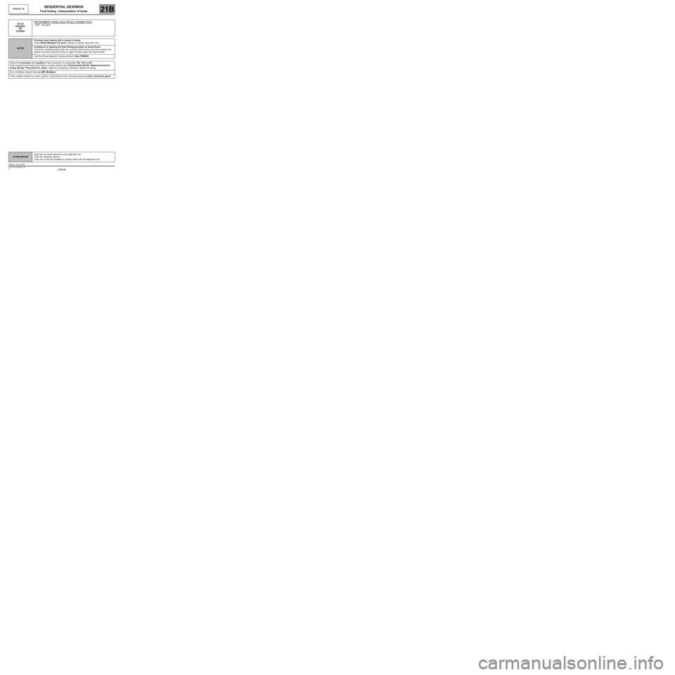
DF150
PRESENT
OR
STOREDINSTRUMENT PANEL MULTIPLEX CONNECTION
1.DEF : No signal
NOTESPriorities when dealing with a number of faults:
If fault DF062 Multiplex line fault is present or stored, deal with it first.
Conditions for applying the fault finding procedure to stored faults:
The fault is declared present after the computer fault memory has been cleared, the
ignition has been switched off and on again and the engine has been started.
Use the Wiring Diagrams Technical Note for New TWINGO.
Check the connection and condition of the connectors of components 120, 119 and 247.
If the connectors are faulty and if there is a repair method (see Technical Note 6015A, Repairing electrical
wiring, W iring: Precautions for repair), repair the connectors; otherwise, replace the wiring.
Run a multiplex network test (see 88B, Multiplex).
If the multiplex network is correct, perform a fault finding of the instrument panel (see 83A, Instrument panel).
AFTER REPAIRDeal with any faults detected by the diagnostic tool.
Clear the computer memory.
Carry out a road test followed by another check with the diagnostic tool.
BVRJH1_V04_DF150
Page 59 of 138
21B-59
MR-413-X44-21B000$472.mif
V2
SEQUENTIAL GEARBOX
Fault finding - Interpretation of faults
Vdiag No: 04
21B
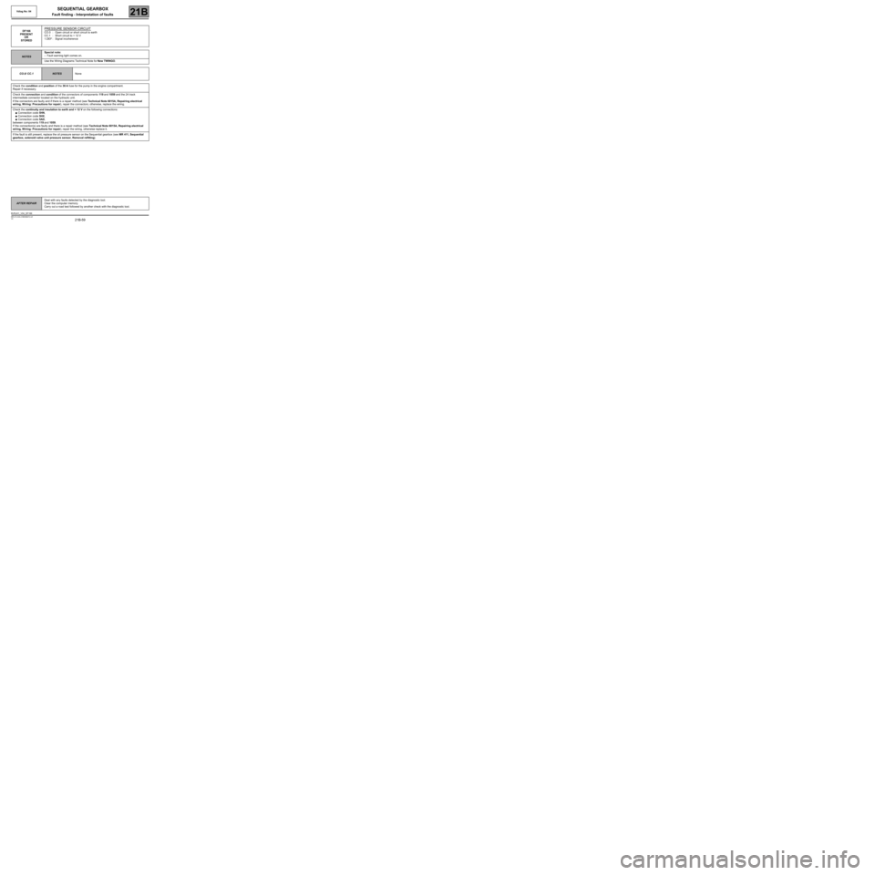
DF166
PRESENT
OR
STOREDPRESSURE SENSOR CIRCUIT
CO.0 : Open circuit or short circuit to earth
CC.1 : Short circuit to + 12 V
1.DEF : Signal incoherence
NOTESSpecial note:
–Fault warning light comes on.
Use the Wiring Diagrams Technical Note for New TWINGO.
CO.0/ CC.1
NOTESNone
Check the condition and position of the 30 A fuse for the pump in the engine compartment.
Repair if necessary.
Check the connection and condition of the connectors of components 119 and 1059 and the 24 track
intermediate connector located on the hydraulic unit.
If the connectors are faulty and if there is a repair method (see Technical Note 6015A, Repairing electrical
wiring, W iring: Precautions for repair), repair the connectors; otherwise, replace the wiring.
Check the continuity and insulation to earth and + 12 V on the following connections:
●Connection code 5HN,
●Connection code 5HX,
●Connection code 5AD,
between components 119 and 1059.
If the connection(s) are faulty and there is a repair method (see Technical Note 6015A, Repairing electrical
wiring, W iring: Precautions for repair), repair the wiring, otherwise replace it.
If the fault is still present, replace the oil pressure sensor on the Sequential gearbox (see MR 411, Sequential
gearbox, solenoid valve unit pressure sensor, Removal refitting).
AFTER REPAIRDeal with any faults detected by the diagnostic tool.
Clear the computer memory.
Carry out a road test followed by another check with the diagnostic tool.
BVRJH1_V04_DF166
Page 60 of 138
21B-60
MR-413-X44-21B000$472.mif
V2
SEQUENTIAL GEARBOX
Fault finding - Interpretation of faults
Vdiag No: 04
21B
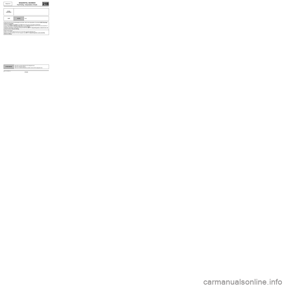
DF166
CONTINUED
1.DEF
NOTESNone
Check the level of oil in the discharged accumulator, refer to the interpretation of command AC081 Discharge
pressure accumulator.
Check the condition and position of the 30 A fuse for the pump in the engine compartment.
Use command AC012 “Hydraulic pump relay” with the diagnostic tool and check that the pump assembly is
working. If the pump is not working, perform the necessary repairs.
If the fault is still present, replace the oil pressure sensor (see MR 411, Sequential gearbox, solenoid valve unit
pressure sensor, Removal refitting).
Switch off the ignition.
Switch on the ignition again and carry out a new check using the diagnostic tool.
Replace the pump assembly if the fault reappears (see MR 411, Sequential gearbox, pump assembly,
Removal refitting).
AFTER REPAIRDeal with any faults detected by the diagnostic tool.
Clear the computer memory.
Carry out a road test followed by another check with the diagnostic tool.