technical data Seat Altea 2010 Repair Manual
[x] Cancel search | Manufacturer: SEAT, Model Year: 2010, Model line: Altea, Model: Seat Altea 2010Pages: 310, PDF Size: 7.46 MB
Page 125 of 310

Lights and visibility123
Safety First
Operating instructions
Practical tips
Technical Data
Front reading lights Switching on the reading light
Press the corresponding button ⇒fig. 81 and ⇒fig. 82 to switch on
the reading light. Switching the reading lights off
Press the corresponding button to switch the reading light off.Rear interior and reading lights* The switch
⇒fig. 83 is used to select the following positions:
Interior light switched off 0
In switch position ⇒fig. 83 , the interior and reading lights are switched
off.
Switching on the reading light
Turn the switch to position (left reading light) or to position (right
reading light).
Courtesy light position
Turn the control to position . The interior lights are automatically switched
on when the vehicle is unlocked or the key removed from the ignition lock The
Fig. 81 Interior roof trim:
front reading lights, type
1Fig. 82 Interior roof trim:
front reading lights, type
2
AB
AB
Fig. 83 Interior roof trim:
rear interior lights and
reading lights.
AC
A1A2
A4
A3
altea_EN Seite 123 Mittwoch, 26. August 2009 6:00 18
Page 127 of 310
Lights and visibility125
Safety First
Operating instructions
Practical tips
Technical Data
Windscreen washersFront windscreen wipers
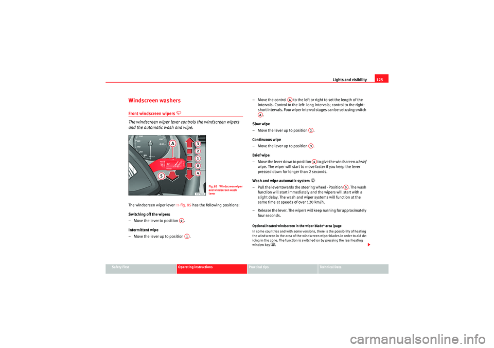
The windscreen wiper lever controls the windscreen wipers
and the automatic wash and wipe.
The windscreen wiper lever ⇒ fig. 85 has the following positions:
Switching off the wipers
– Move the lever to position .
Intermittent wipe
– Move the lever up to position . – Move the control to the left or right to set the length of the
intervals. Control to the left: long intervals; control to the right:
short intervals. Four wiper interval stages can be set using switch
.
Slow wipe
– Move the lever up to position .
Continuous wipe
– Move the lever up to position .
Brief wipe
– Move the lever down to position to give the windscreen a brief
wipe. The wiper will start to move faster if you keep the lever
pressed down for longer than 2 seconds.
Wash and wipe automatic system
– Pull the lever towards the steering wheel - Position . The wash function will start immediately and the wipers will start with a
slight delay. The wash and wiper systems will function at the
same time at speeds of over 120 km/h.
– Release the lever. The wipers will keep running for approximately four seconds.Optional heated windscreen in the wiper blade* area (page
In some countries and with some versions, there is the possibility of heating
the windscreen in the area of the windscreen wiper blades in order to aid de-
icing in the zone. The function is switched on by pressing the rear heating
window key
.
Fig. 85 Windscreen wiper
and windscreen wash
lever
A0A1
AA
AA
A2A3A4
A5
altea_EN Seite 125 Mittwoch, 26. August 2009 6:00 18
Page 129 of 310

Lights and visibility127
Safety First
Operating instructions
Practical tips
Technical Data
Rain sensor*
The rain sensor controls the frequency of the windscreen
wiper intervals, depending on the amount of rain.
Switching on the rain sensor
– Move the windscreen wiper lever into position ⇒fig. 87 .
– Move the control to the left or right to set the sensitivity of the rain sensor. Control to the right: highly sensitive. Control to the
left: less sensitive.The rain sensor is part of the interval wipe function. You will have to switch
the rain sensor back on if you switch off the ignition. This is done by switching
the wiper intermittent function off and back on.
Note
•Do not put stickers on the windscreen in front of the sensor. This may
cause sensor disruption or faults.
Fig. 86 Rain sensor*Fig. 87 Windscreen wiper
lever
A1
AA
altea_EN Seite 127 Mittwoch, 26. August 2009 6:00 18
Page 131 of 310
Lights and visibility129
Safety First
Operating instructions
Practical tips
Technical Data
Headlight washer system
The headlight washers clean the headlight lenses.The headlight washers are activated automatically when the windscreen
washer is used and the windscreen wiper lever is pulled towards the steering
wheel for at least 1.5 seconds – provided the dipped headlights or main
beams are switched on. Clean off stubborn dirt (insects, etc.) from the head-
lights at regular intervals, for instance when filling the fuel tank.
Note
•To ensure that the headlight washers work properly in winter, keep the
nozzle holders in the bumper free of snow and remove any ice with a de-icer
spray.•To remove water, the windscreen wipers will be activated from time to
time, the headlight wipers will be activated every three cycles.MirrorsInterior mirror
It is dangerous to drive if you cannot see clearly through the
rear window.Manual anti-dazzle function for interior mirror
In the basic mirror position, the lever at the bottom edge of the mirror should
be at the front. Pull the lever to the back to select the anti-dazzle function.
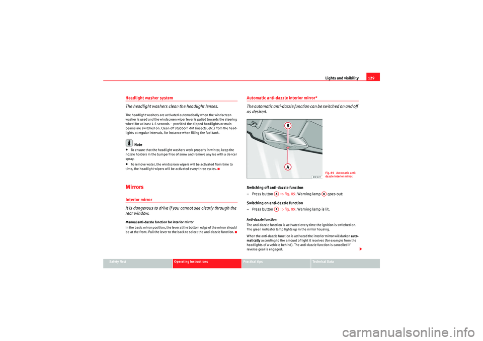
Automatic anti-dazzle interior mirror*
The automatic anti-dazzle function can be switched on and off
as desired.Switching off anti-dazzle function
–Press button ⇒ fig. 89. Warning lamp goes out:
Switching on anti-dazzle function
–Press button ⇒ fig. 89. Warning lamp is lit.Anti-dazzle function
The anti-dazzle function is activated every time the ignition is switched on.
The green indicator lamp ligh ts up in the mirror housing.
When the anti-dazzle function is activated the interior mirror will darken auto-
matically according to the amount of light it receives (for example from the
headlights of a vehicle behind). The anti-dazzle function is cancelled if
reverse gear is engaged.
Fig. 89 Automatic anti-
dazzle interior mirror.
AA
AB
AA
altea_EN Seite 129 Mittwoch, 26. August 2009 6:00 18
Page 133 of 310
Lights and visibility131
Safety First
Operating instructions
Practical tips
Technical Data
Synchronised mirror adjustment
1. Turn the control to the position L ( left exterior mirror ).
2. Turn the rotary knob to position the mirror so that you have a good view to the rear of the vehicle. The right exterior mirror will
be adjusted at the same time (synchronised).
WARNING
•The rear view convex or aspheric mirror increase the field of vision
however the objects appear smaller and further away in the mirrors. If you
use these mirrors to estimate the distance to vehicles behind you when
changing lane, you could make a mistake. Risk of accident.•If possible, use the interior mirror to estimate distances to vehicles
behind you.•Make sure that you do not get your finger trapped between the mirror
and the mirror base when folding back the mirrors. Risk of injury!For the sake of the environment
The exterior mirror heating should be switched off when it is no longer
needed. Otherwise, it is an unnecessary fuel waste.
Note
•If the electrical adjustment ever fails to operate, the mirrors can be
adjusted by hand by lightly pressing the edge of the mirror glass.•In vehicles with electric wing mirrors, the following points should be
observed: if, due to an external force (e.g. a knock while manoeuvring), the
adjustment of the mirror housing is altered, the mirror will have to be
completely folded electrically. Do not readjust the mirror housing by hand, as
this will interfere with the mirror adjuster function.
•The rear view mirrors can be adjusted separately or simultaneously, as
described before.•The wing mirrors folding function does not activate with speeds higher
than 40 km/h.
altea_EN Seite 131 Mittwoch, 26. August 2009 6:00 18
Page 135 of 310
Seats and stowage133
Safety First
Operating instructions
Practical tips
Technical Data
Head restraintsCorrect adjustment of head restraints
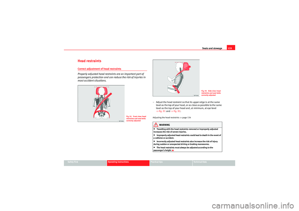
Properly adjusted head restraints are an important part of
passengers protection and can reduce the risk of injuries in
most accident situations.
– Adjust the head restraint so that its upper edge is at the same
level as the top of your head, or as close as possible to the same
level as the top of your head and, at minimum, at eye level
⇒fig. 91 and ⇒fig. 92.Adjusting the head restraints ⇒page 134
WARNING
•Travelling with the head restraints removed or improperly adjusted
increases the risk of severe injuries.•Improperly adjusted head restraints could lead to death in the event of
a collision or accident.•Incorrectly adjusted head restraints also increase the risk of injury
during sudden or unexpected driving or braking manoeuvres.•The head restraints must always be adjusted according to the
passenger's height.
Fig. 91 Front view: head
restraints and seat belts
correctly adjusted
Fig. 92 Side view: head
restraints and seat belts
correctly adjusted
altea_EN Seite 133 Mittwoch, 26. August 2009 6:00 18
Page 137 of 310
Seats and stowage135
Safety First
Operating instructions
Practical tips
Technical Data
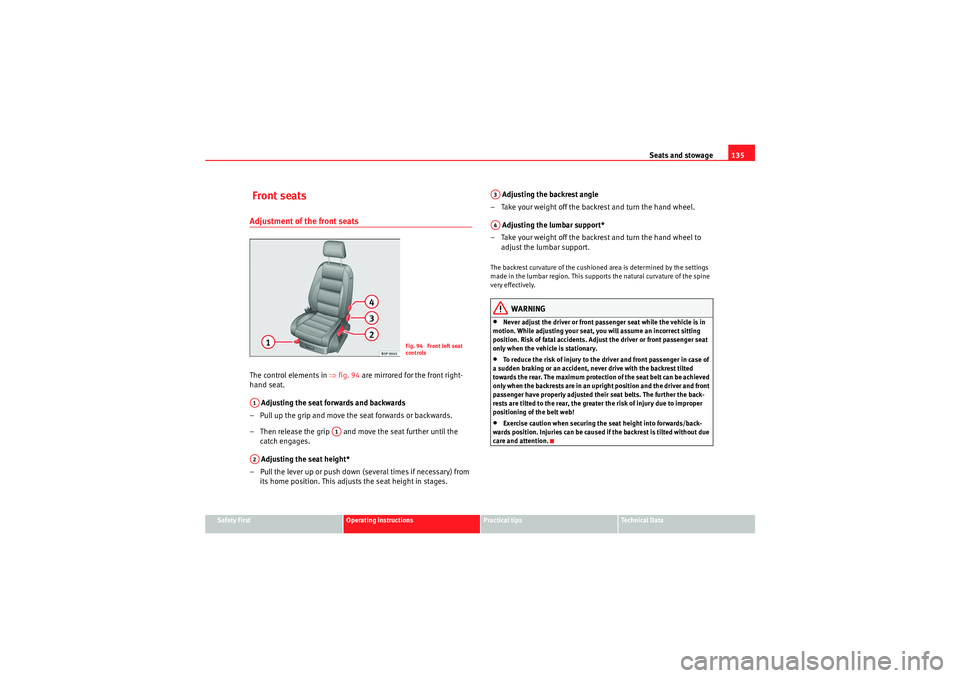
Front seatsAdjustment of the front seatsThe control elements in ⇒fig. 94 are mirrored for the front right-
hand seat.
Adjusting the seat forwards and backwards
– Pull up the grip and move the seat forwards or backwards.
– Then release the grip and move the seat further until the catch engages.
Adjusting the seat height*
– Pull the lever up or push down (several times if necessary) from its home position. This adjusts the seat height in stages. Adjusting the backrest angle
– Take your weight off the backrest and turn the hand wheel.
Adjusting the lumbar support*
– Take your weight off the backrest and turn the hand wheel to adjust the lumbar support.
The backrest curvature of the cushioned area is determined by the settings
made in the lumbar region. This supports the natural curvature of the spine
very effectively.
WARNING
•Never adjust the driver or front passenger seat while the vehicle is in
motion. While adjusting your seat, you will assume an incorrect sitting
position. Risk of fatal accidents. Adjust the driver or front passenger seat
only when the vehicle is stationary.•To reduce the risk of injury to the driver and front passenger in case of
a sudden braking or an accident, never drive with the backrest tilted
towards the rear. The maximum protection of the seat belt can be achieved
only when the backrests are in an upright position and the driver and front
passenger have properly adjusted their seat belts. The further the back-
rests are tilted to the rear, the greater the risk of injury due to improper
positioning of the belt web!•Exercise caution when securing the seat height into forwards/back-
wards position. Injuries can be caused if the backrest is tilted without due
care and attention.
Fig. 94 Front left seat
controls
A1
A1
A2
A3A4
altea_EN Seite 135 Mittwoch, 26. August 2009 6:00 18
Page 139 of 310
Seats and stowage137
Safety First
Operating instructions
Practical tips
Technical Data
Rear seat benchSeat adjustment
The seats may be moved forwards or backwards independently. The
movement can be 1/3 or 2/3 of the seat. There are various possible
positions.
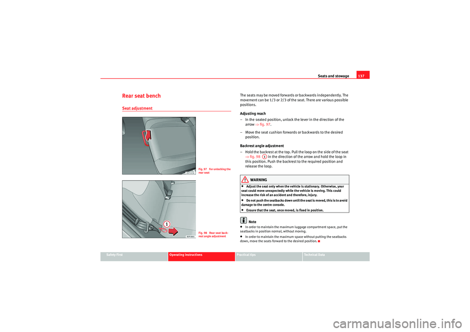
Adjusting reach
– In the seated position, unlock the lever in the direction of the
arrow ⇒fig. 97 .
– Move the seat cushion forwards or backwards to the desired
position.
Backrest angle adjustment
– Hold the backrest at the top. Pull the loop on the side of the seat ⇒fig. 98 in the direction of the arrow and hold the loop in
this position. Push the backrest to the required position and
release the loop.
WARNING
•Adjust the seat only when the vehicle is stationary. Otherwise, your
seat could move unexpectedly while the vehicle is moving. This could
increase the risk of an accident and therefore, injury.•Do not push the seatbacks down until the seat is moved, this is to avoid
damage to the centre console.•Ensure that the seat, once moved, is fixed in position.Note
•In order to maintain the maximum luggage compartment space, put the
seatbacks in position normal, without moving.•In order to maintain the maximum space without putting the seatbacks
down, move the seats forward to the desired position.
Fig. 97 For unlocking the
rear seatFig. 98 Rear seat back-
rest angle adjustment
A1
altea_EN Seite 137 Mittwoch, 26. August 2009 6:00 18
Page 141 of 310
Seats and stowage139
Safety First
Operating instructions
Practical tips
Technical Data
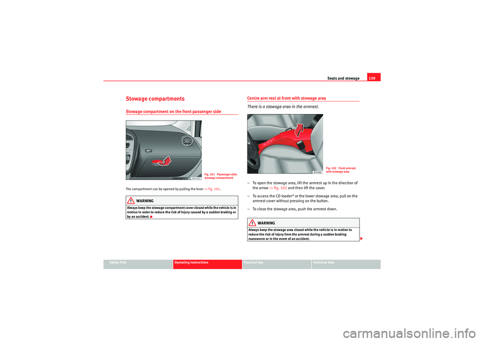
Stowage compartmentsStowage compartment on the front passenger sideThe compartment can be opened by pulling the lever ⇒fig. 101.
WARNING
Always keep the stowage compartment cover closed while the vehicle is in
motion in order to reduce the risk of injury caused by a sudden braking or
by an accident.
Centre arm rest at front with stowage area
There is a stowage area in the armrest.– To open the stowage area, lift the armrest up in the direction of
the arrow ⇒fig. 102 and then lift the cover.
– To access the CD loader* or the lower stowage area, pull on the armrest cover without pressing on the button.
– To close the stowage area, push the armrest down.
WARNING
Always keep the stowage area closed while the vehicle is in motion to
reduce the risk of injury from the armrest during a sudden braking
manoeuvre or in the event of an accident.
Fig. 101 Passenger side:
stowage compartment
Fig. 102 Front armrest
with stowage area
altea_EN Seite 139 Mittwoch, 26. August 2009 6:00 18
Page 143 of 310
Seats and stowage141
Safety First
Operating instructions
Practical tips
Technical Data
WARNING
•The folding tables may not be folded down whilst the vehicle is in
motion and anyone is seated on the second row of seats. There is a risk on
injury during a sudden braking manoeuvre! The table must therefore be
closed and properly secured whilst the vehicle is in motion.•Never place hot drinks in the drink holders. During normal or sudden
driving manoeuvres, sudden braking or an accident, the hot drink could be
spilled. Danger of scalding.Caution
When driving, do not leave open cans in the cup holders. The drink might be
spilt on braking, for example, and could damage the vehicle.Roof stowage compartment*
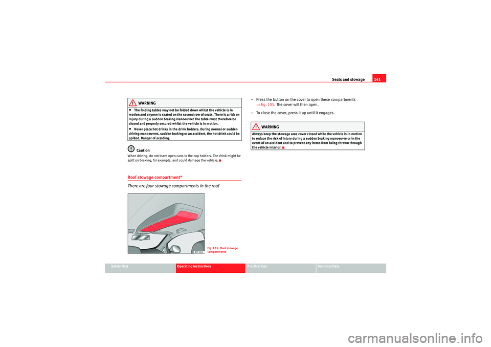
There are four stowage compartments in the roof
– Press the button on the cover to open these compartments ⇒fig. 105 . The cover will then open.
– To close the cover, press it up until it engages.
WARNING
Always keep the stowage area cover closed while the vehicle is in motion
to reduce the risk of injury during a sudden braking manoeuvre or in the
event of an accident and to prevent any items from being thrown through
the vehicle interior.
Fig. 105 Roof stowage
compartments
altea_EN Seite 141 Mittwoch, 26. August 2009 6:00 18