technical data Seat Altea 2010 Manual PDF
[x] Cancel search | Manufacturer: SEAT, Model Year: 2010, Model line: Altea, Model: Seat Altea 2010Pages: 310, PDF Size: 7.46 MB
Page 145 of 310
Seats and stowage143
Safety First
Operating instructions
Practical tips
Technical Data
Luggage compartment net
There is a retaining net in the luggage compartment for
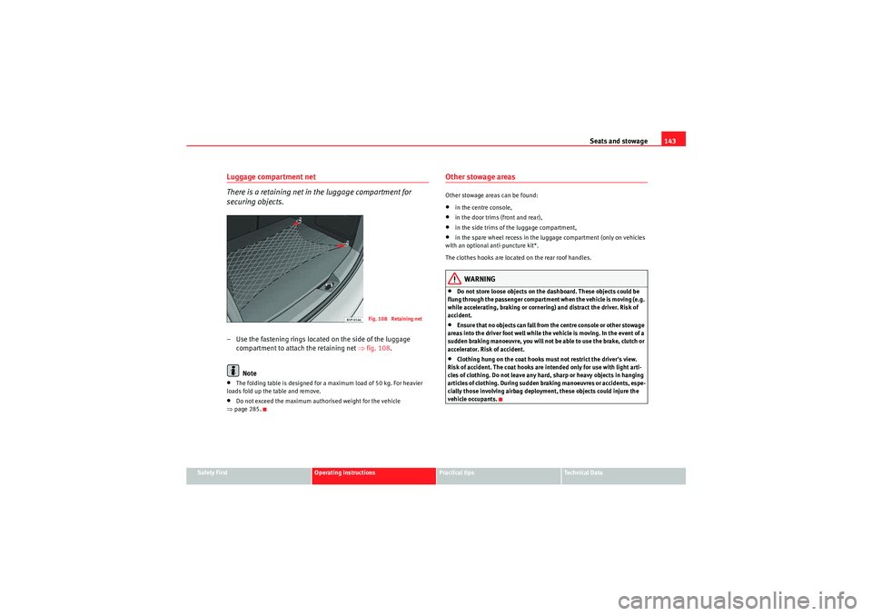
securing objects.– Use the fastening rings located on the side of the luggage
compartment to attach the retaining net ⇒ fig. 108.
Note•The folding table is designed for a maximum load of 50 kg. For heavier
loads fold up the table and remove.•Do not exceed the maximum authorised weight for the vehicle
⇒ page 285.
Other stowage areasOther stowage areas can be found:•in the centre console,•in the door trims (front and rear),•in the side trims of the luggage compartment,•in the spare wheel recess in the luggage compartment (only on vehicles
with an optional anti-puncture kit*.
The clothes hooks are located on the rear roof handles.WARNING
•Do not store loose objects on the dashboard. These objects could be
flung through the passenger compartment when the vehicle is moving (e.g.
while accelerating, braking or cornering) and distract the driver. Risk of
accident.•Ensure that no objects can fall from the centre console or other stowage
areas into the driver foot well while the vehicle is moving. In the event of a
sudden braking manoeuvre, you will not be able to use the brake, clutch or
accelerator. Risk of accident.•Clothing hung on the coat hooks must not restrict the driver's view.
Risk of accident. The coat hooks are intended only for use with light arti-
cles of clothing. Do not leave any hard, sharp or heavy objects in hanging
articles of clothing. During sudden braking manoeuvres or accidents, espe-
cially those involving airbag deployment, these objects could injure the
vehicle occupants.
Fig. 108 Retaining net
altea_EN Seite 143 Mittwoch, 26. August 2009 6:00 18
Page 147 of 310
Seats and stowage145
Safety First
Operating instructions
Practical tips
Technical Data
Opening and closing the armrest* / drink holder*
– To open, pull the loop in the direction of the arrow ⇒page 144,
fig. 110 .
– To close, lift the Drink holder* / armrest* in the direction of the arrow ⇒page 144, fig. 111 .
WARNING
Ensure that the load in the luggage compartment is correctly secured with
the retainer net when travelling with the armrest down ⇒page 143.Multi-purpose* mobile stowage compartment - Fitting and removal
This stowage compartment may only be placed in the central
area of the rear seat
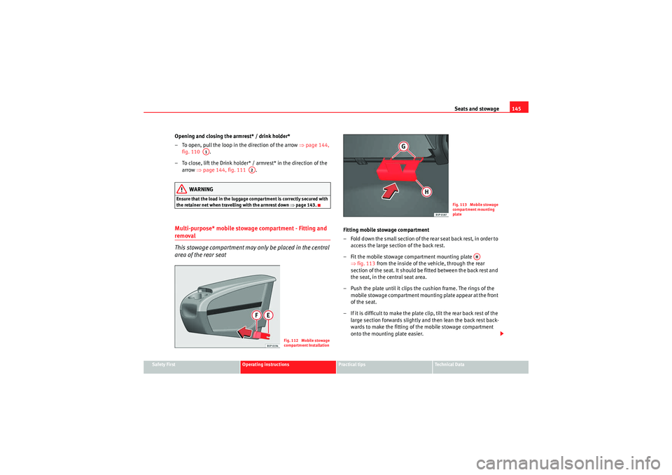
Fitting mobile stowage compartment
– Fold down the small section of the rear seat back rest, in order to
access the large sectio n of the back rest.
– Fit the mobile stowage compartment mounting plate ⇒fig. 113 from the inside of the vehicle, through the rear
section of the seat. It should be fitted between the back rest and
the seat, in the central seat area.
– Push the plate until it clips the cushion frame. The rings of the mobile stowage compartment mounting plate appear at the front
of the seat.
– If it is difficult to make the plate clip, tilt the rear back rest of the large section forwards slightly and then lean the back rest back-
wards to make the fitting of the mobile stowage compartment
onto the mounting plate easier.
A1
A2
Fig. 112 Mobile stowage
compartment Installation
Fig. 113 Mobile stowage
compartment mounting
plate
AH
altea_EN Seite 145 Mittwoch, 26. August 2009 6:00 18
Page 149 of 310
Seats and stowage147
Safety First
Operating instructions
Practical tips
Technical Data
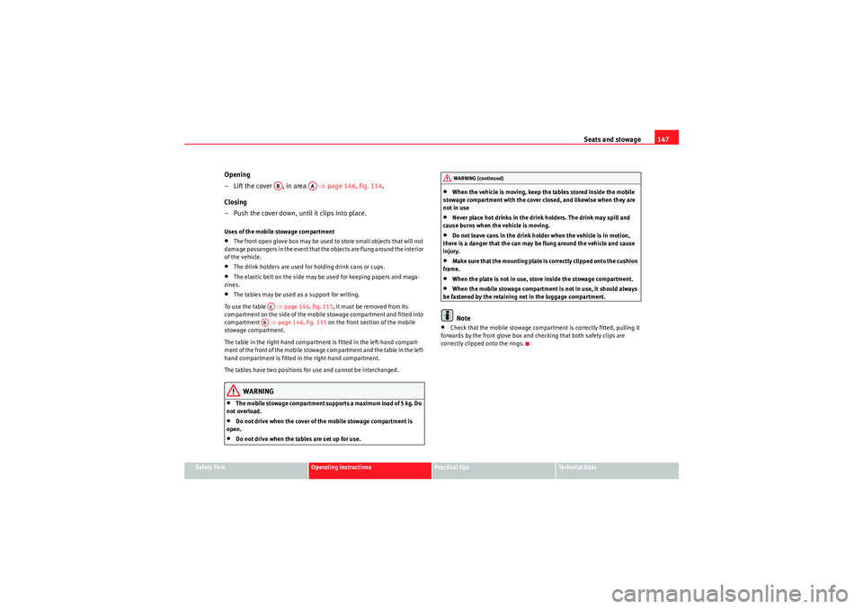
Opening
– Lift the cover , in area ⇒ page 146, fig. 114.
Closing
– Push the cover down, until it clips into place.Uses of the mobile stowage compartment•The front open glove box may be used to store small objects that will not
damage passengers in the event that the objects are flung around the interior
of the vehicle.•The drink holders are used for holding drink cans or cups.•The elastic belt on the side may be used for keeping papers and maga-
zines.•The tables may be used as a support for writing.
To use the table ⇒page 146, fig. 115, it must be removed from its
compartment on the side of the mobile stowage compartment and fitted into
compartment ⇒page 146, fig. 115 on the front section of the mobile
stowage compartment.
The table in the right-hand compartment is fitted in the left-hand compart-
ment of the front of the mobile stowage compartment and the table in the left-
hand compartment is fitted in the right-hand compartment.
The tables have two positions for use and cannot be interchanged.WARNING
•The mobile stowage compartment supports a maximum load of 5 kg. Do
not overload.•Do not drive when the cover of the mobile stowage compartment is
open.•Do not drive when the tables are set up for use.
•When the vehicle is moving, keep the tables stored inside the mobile
stowage compartment with the cover closed, and likewise when they are
not in use•Never place hot drinks in the drink holders. The drink may spill and
cause burns when the vehicle is moving.•Do not leave cans in the drink holder when the vehicle is in motion,
there is a danger that the can may be flung around the vehicle and cause
injury.•Make sure that the mounting plate is correctly clipped onto the cushion
frame.•When the plate is not in use, store inside the stowage compartment.•When the mobile stowage compartment is not in use, it should always
be fastened by the retaining net in the luggage compartment.Note
•Check that the mobile stowage compartment is correctly fitted, pulling it
forwards by the front glove box and checking that both safety clips are
correctly clipped onto the rings.
AB
AA
ACAD
WARNING (continued)
altea_EN Seite 147 Mittwoch, 26. August 2009 6:00 18
Page 151 of 310
Seats and stowage149
Safety First
Operating instructions
Practical tips
Technical Data
Electrical sockets
Electrical equipment can be connected to any of the 12 volt
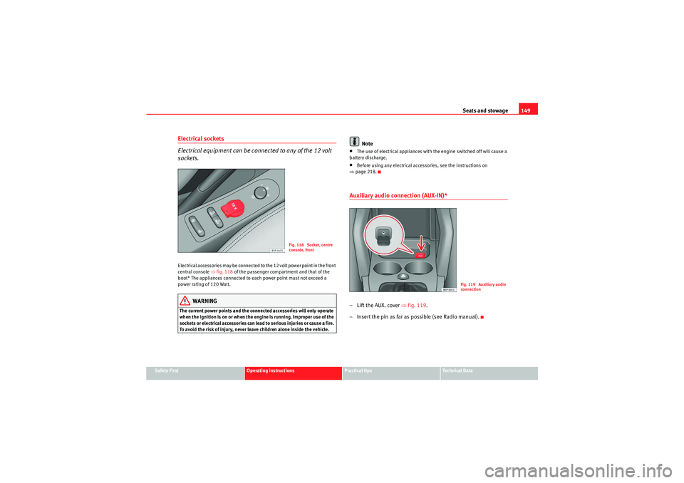
sockets.Electrical accessories may be connected to the 12 volt power point in the front
central console ⇒fig. 118 of the passenger compartment and that of the
boot* The appliances connected to each power point must not exceed a
power rating of 120 Watt.
WARNING
The current power points and the connected accessories will only operate
when the ignition is on or when the engine is running. Improper use of the
sockets or electrical accessories can lead to serious injuries or cause a fire.
To avoid the risk of injury, never leave children alone inside the vehicle.
Note
•The use of electrical appliances with the engine switched off will cause a
battery discharge.•Before using any electrical accessories, see the instructions on
⇒ page 218.Auxiliary audio connection (AUX-IN)*– Lift the AUX. cover ⇒fig. 119 .
– Insert the pin as far as possible (see Radio manual).
Fig. 118 Socket, centre
console, front
Fig. 119 Auxiliary audio
connection
altea_EN Seite 149 Mittwoch, 26. August 2009 6:00 18
Page 153 of 310
Seats and stowage151
Safety First
Operating instructions
Practical tips
Technical Data
First-aid kit, warning triangle, fire
extinguisherWarning triangle
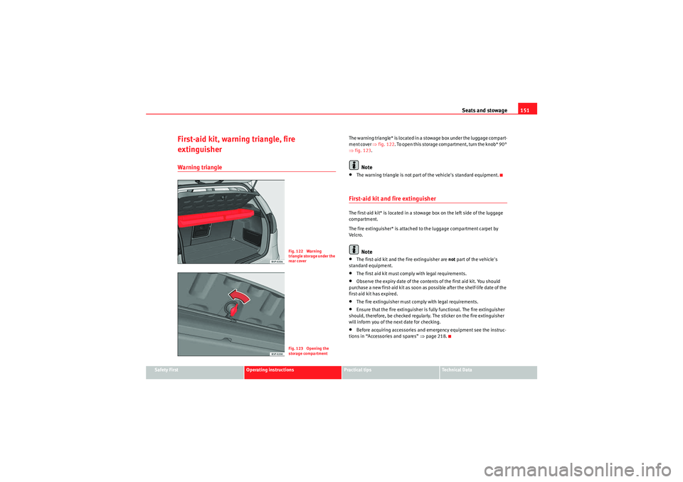
The warning triangle* is located in a stowage box under the luggage compart-
ment cover ⇒fig. 122 . To open this storage compartment, turn the knob* 90°
⇒ fig. 123 .
Note
•The warning triangle is not part of the vehicle's standard equipment.First-aid kit and fire extinguisherThe first-aid kit* is located in a stowage box on the left side of the luggage
compartment.
The fire extinguisher* is attached to the luggage compartment carpet by
Velcro.
Note
•The first-aid kit and the fire extinguisher are not part of the vehicle's
standard equipment.•The first aid kit must comply with legal requirements.•Observe the expiry date of the contents of the first aid kit. You should
purchase a new first-aid kit as soon as possible after the shelf-life date of the
first-aid kit has expired.•The fire extinguisher must comply with legal requirements.•Ensure that the fire extinguisher is fully functional. The fire extinguisher
should, therefore, be checked regularly. The sticker on the fire extinguisher
will inform you of the next date for checking.•Before acquiring accessories and emergency equipment see the instruc-
tions in “Accessories and spares” ⇒page 218.
Fig. 122 Warning
triangle storage under the
rear coverFig. 123 Opening the
storage compartment
altea_EN Seite 151 Mittwoch, 26. August 2009 6:00 18
Page 155 of 310
Seats and stowage153
Safety First
Operating instructions
Practical tips
Technical Data
Rear shelfRemoving the cover
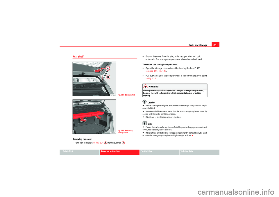
– Unhook the loops ⇒fig. 124 from housings – Extract the cover from its slot, in its rest position and pull
outwards. The storage compartment should remain closed.
To remove the storage compartment
– Open the storage compartment by turning the knob* 90° ⇒page 151, fig. 123 .
– Pull outwards until the compartment is freed from the pivot point ⇒fig. 125 .
WARNING
Do not place heavy or hard objects on the open stowage compartment,
because they will endanger the vehicle occupants in case of sudden
braking.
Caution
•Before closing the tailgate, ensure that the stowage compartment tray is
correctly fitted.•An overloaded boot could mean that the rear stowage tray is not correctly
seated and it may be bent or damaged.•If the boot is overloaded, remove the tray.Note
•Ensure that, when placing items of clothing on the luggage compartment
cover, rear visibility is not reduced.•If the vehicle is fitted with a storage compartment*, it should only be used
to store the emergency triangles and light-weight articles.
Fig. 124 Storage shelfFig. 125 Removing
storage shelf
AB
AA
altea_EN Seite 153 Mittwoch, 26. August 2009 6:00 18
Page 156 of 310
Seats and stowage
154Roof carrier*Please observe the following points if you intend to carry loads on the roof:•For safety reasons, only luggage racks and accessories approved by SEAT
should be used.•It is imperative to precisely follow the fitting instructions included for the
rack, taking special care when fitting the front bar in the holes designed for
this and the rear bar between the marks on the upper part of the rear door
frame while respecting the correct direction of travel indicated in the installa-
tion manual. Not following these instructions may damage the bodywork.•Pay special attention to the tightening torque of the attachment bolts and
check them following a short journey. If necessary, retighten the bolts and
check them at regular intervals.•Distribute the load evenly. A maximum load of 40 kg only is permitted for
each roof carrier system support bar, the load must be distributed evenly
along the entire length. However, the maximum load permitted for the entire
roof (including the support system) of 75 kg must not be exceeded nor should
the total weight of the vehicle be exceeded. See the chapter on “Technical
Data”.•When transporting heavy or large objects on the roof, any change in the
normal vehicle behaviour due to a change in the centre of gravity or an
increased wind resistance must be taken into account. For this reason, a suit-
able speed and driving style must be used.•For those vehicles fitted with a sunroof*, ensure that it does not interfere
with the load on the roof carrier system when opened.
altea_EN Seite 154 Mittwoch, 26. August 2009 6:00 18
Page 157 of 310
Heating, Ventilation and Air conditioning155
Safety First
Operating instructions
Practical tips
Technical Data
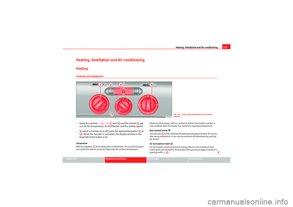
Heating, Ventilation and Air conditioningHeatingControls and equipment–Using the controls ⇒fig. 126 and and the control you
can set the temperature, air distribution and the turbine speed.
– To switch a function on or off, press the appropriate button or . When the function is activated, the display window in the
lower left of the button is lit.Te m p e r a t u r e
With the regulator the heating level is determined. The required tempera-
ture inside the vehicle cannot be lower than the ambient temperature. Maximum heat output, which is needed to defrost the windows quickly, is
only available when the engine has reached its operating temperature.
Rear window heater
This function will be switched off automatically approximately
20 minutes
after being switched on. It can also be switched off beforehand by pushing
the button
Air recirculation mode
Air recirculation mode prevents strong odours in the outside air from
entering the vehicle interior, for example when passing through a tunnel or in
queuing traffic ⇒ .
Fig. 126 On the dash panel there are the heating
controls
A1
A4
A5A2
A3
A1
A2
A3
altea_EN Seite 155 Mittwoch, 26. August 2009 6:00 18
Page 159 of 310
Heating, Ventilation and Air conditioning157
Safety First
Operating instructions
Practical tips
Technical Data
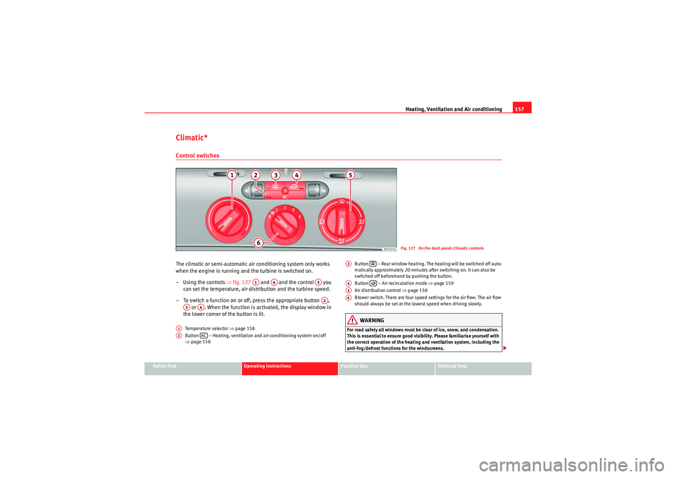
Climatic*Control switchesThe climatic or semi-automatic air conditioning system only works
when the engine is running and the turbine is switched on.
–Using the controls ⇒fig. 127 and and the control you
can set the temperature, air distribution and the turbine speed.
– To switch a function on or off, press the appropriate button , or . When the function is activated, the display window in
the lower corner of the button is lit.
Temperature selector ⇒page 158
Button – Heating, ventilation and air-conditioning system on/off
⇒ page 158 Button – Rear window heating. The heating will be switched off auto-
matically approximately
20 minutes after switching on. It can also be
switched off beforehand by pushing the button.
Button – Air recirculation mode ⇒page 159
Air distribution control ⇒page 158
Blower switch. There are four speed settings for the air flow. The air flow
should always be set at the lowest speed when driving slowly.
WARNING
For road safety all windows must be clear of ice, snow, and condensation.
This is essential to ensure good visibility. Please familiarise yourself with
the correct operation of the heating and ventilation system, including the
anti-fog/defrost functions for the windscreens.
Fig. 127 On the dash panel: Climatic controls
A1
A4
A5A2
A3
A4
A1A2
AC
A3
A4
A5A6
altea_EN Seite 157 Mittwoch, 26. August 2009 6:00 18
Page 161 of 310
Heating, Ventilation and Air conditioning159
Safety First
Operating instructions
Practical tips
Technical Data
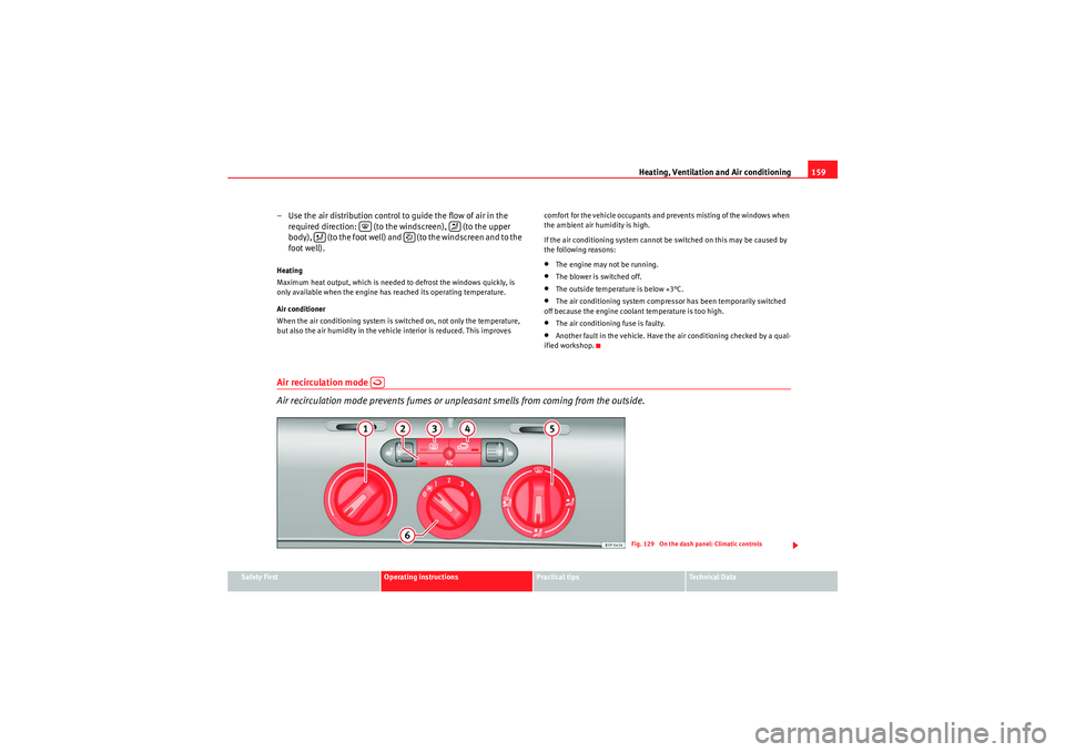
– Use the air distribution control to guide the flow of air in the
required direction: (to the windscreen), (to the upper
body), (to the foot well) and (to the windscreen and to the
foot well).Heating
Maximum heat output, which is needed to defrost the windows quickly, is
only available when the engine has reached its operating temperature.
Air conditioner
When the air conditioning system is switched on, not only the temperature,
but also the air humidity in the vehicle interior is reduced. This improves comfort for the vehicle occupants and prevents misting of the windows when
the ambient air humidity is high.
If the air conditioning system cannot be switched on this may be caused by
the following reasons:
•The engine may not be running.•The blower is switched off.•The outside temperature is below +3°C.•The air conditioning system compressor has been temporarily switched
off because the engine coolant temperature is too high.•The air conditioning fuse is faulty.•Another fault in the vehicle. Have the air conditioning checked by a qual-
ified workshop.
Air recirculation mode
Air recirculation mode prevents fumes or unpleasant smells from coming from the outside.
Fig. 129 On the dash panel: Climatic controls
altea_EN Seite 159 Mittwoch, 26. August 2009 6:00 18