technical specifications Seat Exeo ST 2011 Owner's manual
[x] Cancel search | Manufacturer: SEAT, Model Year: 2011, Model line: Exeo ST, Model: Seat Exeo ST 2011Pages: 319, PDF Size: 5.12 MB
Page 241 of 319
239
Checking and refilling levels
WARNING (Continued)
● A highly explosive mixture of gases is released when the battery is
under charge. The batteries should be charged in a well-ventilated room
only.
● Keep children away from acid and batteries.
● Before working on the electrical system, you must switch off the en-
gine, the ignition and all consumers. The negative cable on the battery
must be disconnected. When a light bulb is changed, you need only
switch off the light.
● Deactivate the anti-theft alarm by unlocking the vehicle before you
disconnect the battery! The alarm will otherwise be triggered.
● When disconnecting the battery from the vehicle electrical system,
disconnect first the negative cable and then the positive cable.
● Switch off all electrical consumers before reconnecting the battery.
Reconnect first the positive cable and then the negative cable. Never re-
verse the polarity of the connections. This could cause an electrical fire.
● Never charge a frozen battery, or one which has thawed. This could
result in explosions and chemical burns. Always replace a battery which
has frozen. A flat battery can freeze at temperatures around 0 °C.
● Ensure that the vent hose is always connected to the battery.
● Never use a defective battery. This could cause an explosion. Replace
a damaged battery immediately.
CAUTION
● Never disconnect the battery if the ignition is switched on or if the en-
gine is running. This could damage the electrical system or electronic com-
ponents.
● Do not expose the battery to direct sunlight over a long period of time,
as the intense ultraviolet radiation can damage the battery housing.
● If the vehicle is left standing in cold conditions for a long period, protect
the battery from freezing. If it freezes it will be damaged. Charging the battery
A fully-charged battery is important for reliable starting.
– Note the warnings ⇒
in Important safety warnings for han-
dling a vehicle battery on page 238 and ⇒ .
– Switch off the ignition and all electrical equipment.
– Only if fast-charging: both battery cables must be disconnected
(first the negative cable, then the positive cable).
– Connect the charger cables to the battery terminals, noting the
colour code (red = positive; black or brown = negative).
– Now connect the battery charger to the power socket and switch
on.
– After charging the battery: switch off the battery charger and
disconnect the power point cable.
– Finally disconnect the charger cables from the battery.
– If necessary, reconnect both battery cables to the battery (first
the positive cable, then the negative cable).
When charging with a low current (for instance with a small battery charger)
the battery does not normally have to be disconnected. However, both bat-
tery cables must be disconnected before fast-charging the battery with a
high current. However, always follow the instructions given by the manufac-
turer of the battery charger.
The fast-charging procedure for a battery is dangerous ⇒
in Important
safety warnings for handling a vehicle battery on page 238, as it requires a
special charger and the corresponding level of knowledge. We therefore rec-
ommend that this work should only be performed by a qualified workshop.
Safety FirstOperating InstructionsPractical TipsTechnical Specifications
Page 243 of 319
241
Wheels and tyres
Wheels and tyres
Wheels
General notes
Avoiding damage
– If you have to drive over a kerb or similar obstacle, drive very
slowly and at a right angle.
– Keep grease, oil and fuel off the tyres.
– Inspect the tyres regularly for damage (cuts, cracks or blisters,
etc.). Remove any foreign objects embedded in the treads.
Storing tyres
– When you remove the tyres, mark them in order to maintain the
same direction of rotation when they are installed again.
– When removed, the wheels and/or tyres should be stored in a
cool, dry and preferably dark location.
– Store tyres in a vertical position if they are not fitted on wheel
rims.
New tyres
New tyres have to be run in.
The tread depth of new tyres may vary, according to the type and make of
tyre and the tread pattern. Concealed damage
Damage to tyres and rims is often not readily visible. If you notice unusual
vibrations or the vehicle pulling to one side, this may indicate that one of
the tyres is damaged. The tyres should be checked immediately by an Au-
thorised Service Centre.
Tyres with directional tread pattern
An arrow on the tyre sidewall indicates the direction of rotation on tyres with
directional tread. Always observe the direction of rotation indicated when
fitting the wheel. This guarantees optimum grip and helps to avoid aqua-
planing, excessive noise and wear.
WARNING
● New tyres do not have maximum grip during the first 500 km. Drive
particularly carefully to avoid possible accidents.
● Never drive with damaged tyres. This may cause an accident.
● If you notice unusual vibrations or if the vehicle pulls to one side
when driving, stop the vehicle immediately and check the tyres for dam-
age.
Checking tyre pressure
The correct tyre pressure can be seen on the sticker on the
inside of the tank flap.
1. Read the required tyre inflation pressure from the sticker. The values refer to Summer tyres. For Winter tyres, you must add 0.2
bar to the values given on the sticker.
Safety FirstOperating InstructionsPractical TipsTechnical Specifications
Page 245 of 319
243
Wheels and tyres
Significant tyre pressure loss
The tyre symbol is displayed and indicates that the tyre pressure
of at least one tyre is insufficient.
– Stop the vehicle.
– Switch the engine off.
– Check the tyre(s).
– Change the wheel if necessary.
Tyre pressure monitoring (RKA+)*
The tyre pressure monitor display on the instrument panel
indicates if the pressure is too low.
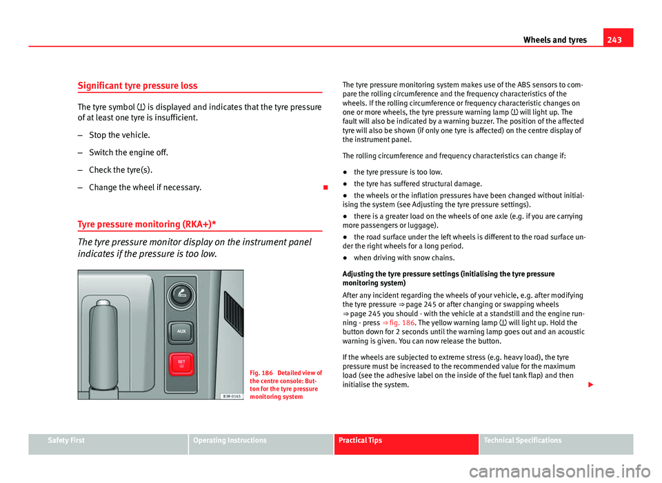
Fig. 186 Detailed view of
the centre console: But-
ton for the tyre pressure
monitoring system The tyre pressure monitoring system makes use of the ABS sensors to com-
pare the rolling circumference and the frequency characteristics of the
wheels. If the rolling circumference or frequency characteristic changes on
one or more wheels, the tyre pressure warning lamp will light up. The
fault will also be indicated by a warning buzzer. The position of the affected
tyre will also be shown (if only one tyre is affected) on the centre display of
the instrument panel.
The rolling circumference and frequency characteristics can change if:
●
the tyre pressure is too low.
● the tyre has suffered structural damage.
● the wheels or the inflation pressures have been changed without initial-
ising the system (see Adjusting the tyre pressure settings).
● there is a greater load on the wheels of one axle (e.g. if you are carrying
more passengers or luggage).
● the road surface under the left wheels is different to the road surface un-
der the right wheels for a long period.
● when driving with snow chains.
Adjusting the tyre pressure settings (initialising the tyre pressure
monitoring system)
After any incident regarding the wheels of your vehicle, e.g. after modifying
the tyre pressure ⇒ page 245 or after changing or swapping wheels
⇒ page 245 you should - with the vehicle at a standstill and the engine run- ning - press ⇒ fig. 186. The yellow warning lamp will light up. Hold the
button down for 2 seconds until the warning lamp goes out and an acoustic
warning is given. You can now release the button.
If the wheels are subjected to extreme stress (e.g. heavy load), the tyre
pressure must be increased to the recommended value for the maximum
load (see the adhesive label on the inside of the fuel tank flap) and then
initialise the system.
Safety FirstOperating InstructionsPractical TipsTechnical Specifications
Page 247 of 319
245
Wheels and tyres
Tyre service life
The service life of tyres is dependent on tyre pressure, driv-
ing style and fitting.
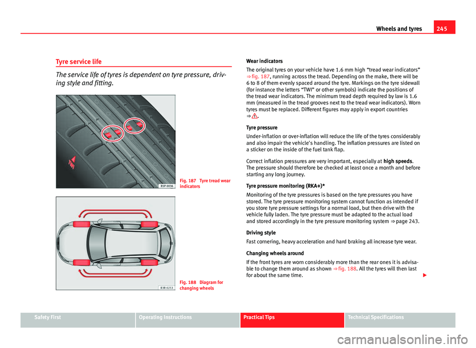
Fig. 187 Tyre tread wear
indicators
Fig. 188 Diagram for
changing wheels Wear indicators
The original tyres on your vehicle have 1.6 mm high “tread wear indicators”
⇒ fig. 187, running across the tread. Depending on the make, there will be
6 to 8 of them evenly spaced around the tyre. Markings on the tyre sidewall
(for instance the letters “TWI” or other symbols) indicate the positions of
the tread wear indicators. The minimum tread depth required by law is 1.6
mm (measured in the tread grooves next to the tread wear indicators). Worn
tyres must be replaced. Different figures may apply in export countries
⇒
.
Tyre pressure
Under-inflation or over-inflation will reduce the life of the tyres considerably
and also impair the vehicle's handling. The inflation pressures are listed on
a sticker on the inside of the fuel tank flap.
Correct inflation pressures are very important, especially at high speeds.
The pressure should therefore be checked at least once a month and before
starting any long journey.
Tyre pressure monitoring (RKA+)*
Monitoring of the tyre pressures is based on the tyre pressures you have
stored. The tyre pressure monitoring system cannot function as intended if
you store tyre pressure settings for a normal load, but then drive with the
vehicle fully laden. The tyre pressure must be adapted to the actual load
and stored accordingly in the tyre pressure monitoring system ⇒ page 243.
Driving style
Fast cornering, heavy acceleration and hard braking all increase tyre wear.
Changing wheels around
If the front tyres are worn considerably more than the rear ones it is advisa-
ble to change them around as shown ⇒ fig. 188. All the tyres will then last
for about the same time.
Safety FirstOperating InstructionsPractical TipsTechnical Specifications
Page 249 of 319
247
Wheels and tyres
it if necessary. We recommend you contact Technical Service. If more than
one tyre is being used under emergency conditions, this reduces the dis-
tance which can be travelled.
Starting driving in emergency conditions
When loss in tyre pressure is displayed on the instrument panel, this means
that at least one tyre is being driven in emergency conditions ⇒
.
End of emergency operation
Do not drive on if:
● smoke is coming from one of the tyres,
● there is a smell of rubber,
● the vehicle vibrates,
● there is a rattling noise.
When is it no longer possible to continue driving even using run-flat tyres?
● If the Electronic Stability Programme (ESP) is out of operation.
● If the tyre pressure monitoring system* does not work.
● If one of the tyres has been severely damaged in an accident, etc. If a
tyre has been badly damaged there is a risk that parts of the tread can be
thrown off and cause damage to the fuel lines, brake pipes or fuel filler.
● It is also advisable to stop driving if severe vibrations occur, or if the
wheel starts overheating and gives off smoke.
WARNING
When driving in emergency conditions, the driving quality of the vehicle
is considerably impaired.
● The maximum permitted speed of 80 km/h is subject to road and
weather conditions. Please observe legal requirements when doing so.
● Avoid sharp turns and rapid manoeuvres, and brake earlier than usu-
al.
WARNING (Continued)
● Avoid driving over obstacles (for example kerbs) or potholes.
● If one or more tyres are being driven in emergency conditions, the
driving quality of the vehicle is impaired and there is a risk of accident.
Note
● The run-flat tyres do not “deflate” on losing pressure because they are
supported on the reinforced sides. Therefore defects in the tyre cannot be
detected with a visual inspection.
● Snow chains must not be used on front tyres used in emergency condi-
tions.
New tyres and wheels
New tyres and wheels have to be run in.
The tyres and wheel rims are an essential part of the vehicle's design. The
tyres and rims approved by SEAT are specially matched to the characteris-
tics of the vehicle and make a major contribution to good road holding and
safe handling ⇒
.
Tyres should be replaced at least in pairs and not individually (i.e. both front
tyres or both rear tyres together). A knowledge of tyre designations makes it
easier to choose the correct tyres. Radial tyres have the tyre designations
marked on the sidewall, for example: 195/65 R15 91T
This contains the following information: Tyre width in mm
Height/width ratio in %
Tyre construction: Radial
195
65
R
Safety FirstOperating InstructionsPractical TipsTechnical Specifications
Page 251 of 319
249
Wheels and tyres
WARNING
If the wheel bolts are not tightened correctly, the wheel could become
loose while driving. Risk of accident.
● The wheel bolts must be clean and turn easily. Never apply grease or
oil to them.
● Use only wheel bolts which belong to the wheel.
● If the torque of the wheel bolts is too low, they could loosen whilst
the vehicle is in motion. Risk of accident! If the tightening torque is too
high, the wheel bolts and threads can be damaged.
CAUTION
The prescribed torque for wheel bolts for steel and alloy wheels is 120 Nm.
Winter tyres
Winter tyres will improve the vehicles handling on snow and
ice.
In winter conditions winter tyres will considerably improve the vehicle's han-
dling. The design of summer tyres (width, rubber compound, tread pattern)
gives less grip on ice and snow.
Winter tyres must be inflated to a pressure 0.2 bar higher than the pres-
sures specified for summer tyres (see sticker on tank flap).
Winter tyres must be fitted on all four wheels.
Information on permitted winter tyre sizes can be found in the vehicle's reg-
istration documents. Use only radial winter tyres. All tyre sizes listed in the
vehicle documentation also apply to winter tyres.
Winter tyres lose their effectiveness when the tread is worn down to a depth
of 4 mm. The speed rating code ⇒
page 247, New tyres and wheels determines the
following speed limits for winter tyres: ⇒
max. 160 km/h
max. 180 km/h
max. 190 km/h
max. 210 km/h
In some countries, vehicles which can exceed the speed rating of the fitted
tyre must have an appropriate sticker in the driver's field of view. These
stickers are available from your Authorised Service Centre. The legal require-
ments of each country must be followed.
Do not have winter tyres fitted for unnecessarily long periods. Vehicles with
summer tyres handle better when the roads are free of snow and ice.
If you have a flat tyre, please refer to the notes on the spare wheel
⇒ page 247, New tyres and wheels.
WARNING
The maximum speed for the winter tyres must not be exceeded. Other-
wise, this could lead to tyre damage and risk of accident.
For the sake of the environment
Fit your summer tyres again as soon as possible. They are quieter, do not
wear so quickly and reduce fuel consumption.
Snow chains
Snow chains may be fitted only to the front wheels, and only to certain tyre
sizes ⇒ page 295.
Q
S
T
H
Safety FirstOperating InstructionsPractical TipsTechnical Specifications
Page 253 of 319
251
If and when
If and when
Tools, tyre repair kit and spare wheel Tools
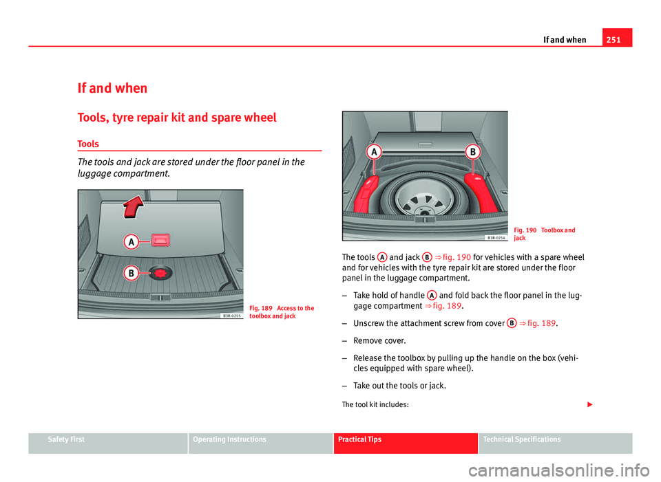
The tools and jack are stored under the floor panel in the
luggage compartment.
Fig. 189 Access to the
toolbox and jack
Fig. 190 Toolbox and
jack
The tools A
and jack B ⇒ fig. 190 for vehicles with a spare wheel
and for vehicles with the tyre repair kit are stored under the floor
panel in the luggage compartment.
– Take hold of handle A
and fold back the floor panel in the lug-
gage compartment ⇒ fig. 189.
– Unscrew the attachment screw from cover B
⇒ fig. 189.
– Remove cover.
– Release the toolbox by pulling up the handle on the box (vehi-
cles equipped with spare wheel).
– Take out the tools or jack.
The tool kit includes:
Safety FirstOperating InstructionsPractical TipsTechnical Specifications
Page 255 of 319
253
If and when
Spare steel rim wheel
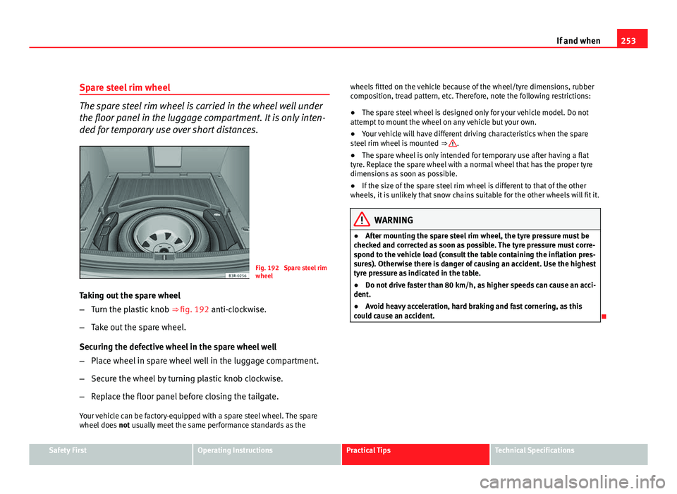
The spare steel rim wheel is carried in the wheel well under
the floor panel in the luggage compartment. It is only inten-
ded for temporary use over short distances.
Fig. 192 Spare steel rim
wheel
Taking out the spare wheel
– Turn the plastic knob ⇒ fig. 192 anti-clockwise.
– Take out the spare wheel.
Securing the defective wheel in the spare wheel well
– Place wheel in spare wheel well in the luggage compartment.
– Secure the wheel by turning plastic knob clockwise.
– Replace the floor panel before closing the tailgate.
Your vehicle can be factory-equipped with a spare steel wheel. The spare
wheel does not usually meet the same performance standards as the wheels fitted on the vehicle because of the wheel/tyre dimensions, rubber
composition, tread pattern, etc. Therefore, note the following restrictions:
●
The spare steel wheel is designed only for your vehicle model. Do not
attempt to mount the wheel on any vehicle but your own.
● Your vehicle will have different driving characteristics when the spare
steel rim wheel is mounted ⇒
.
● The spare wheel is only intended for temporary use after having a flat
tyre. Replace the spare wheel with a normal wheel that has the proper tyre
dimensions as soon as possible.
● If the size of the spare steel rim wheel is different to that of the other
wheels, it is unlikely that snow chains suitable for the other wheels will fit it.
WARNING
● After mounting the spare steel rim wheel, the tyre pressure must be
checked and corrected as soon as possible. The tyre pressure must corre-
spond to the vehicle load (consult the table containing the inflation pres-
sures). Otherwise there is danger of causing an accident. Use the highest
tyre pressure as indicated in the table.
● Do not drive faster than 80 km/h, as higher speeds can cause an acci-
dent.
● Avoid heavy acceleration, hard braking and fast cornering, as this
could cause an accident.
Safety FirstOperating InstructionsPractical TipsTechnical Specifications
Page 257 of 319
255
If and when
– The inflation pressure of the newly fitted spare tyre must be
checked as soon as possible.
– Have the tightening torque of the wheel bolts checked as soon
as possible with a torque wrench. It must be 120 Nm (always
when cold)
– Have the flat tyre replaced as quickly as possible.
Note
● If you notice that the wheel bolts are rusty and difficult to turn when
changing a wheel, they must be replaced before having the tightening tor-
que checked.
● For safety reasons, drive at moderate speeds until the wheel bolt tight-
ening torque has been checked. Loosening and tightening the wheel bolts
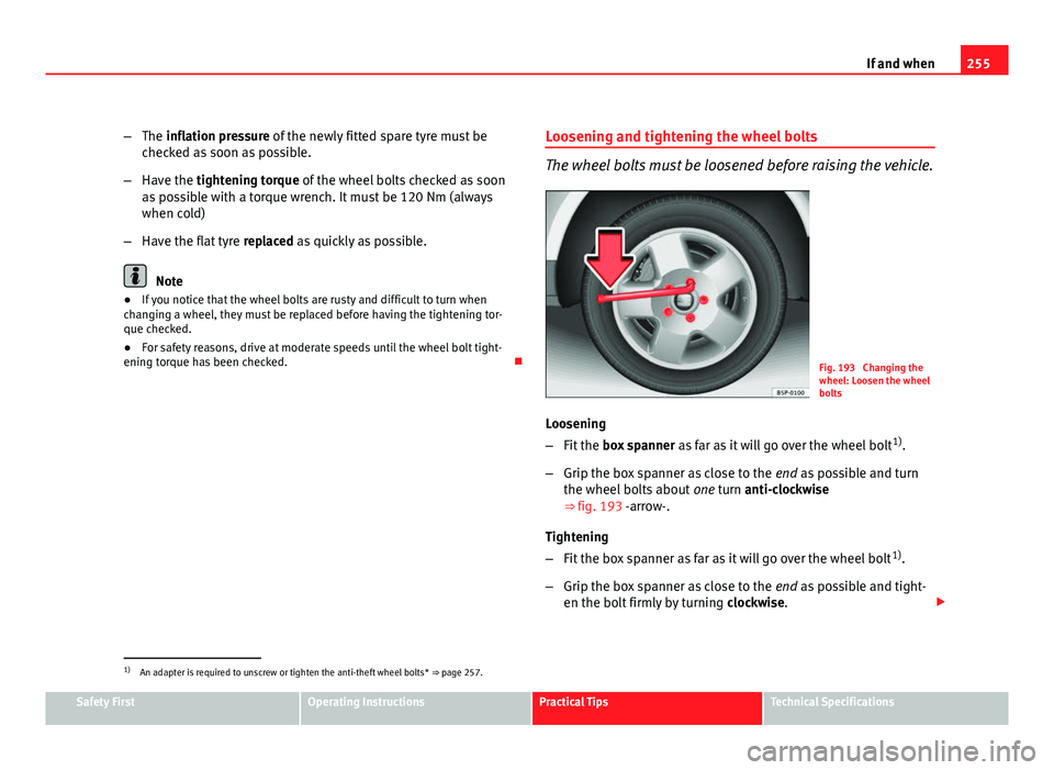
The wheel bolts must be loosened before raising the vehicle.
Fig. 193 Changing the
wheel: Loosen the wheel
bolts
Loosening
– Fit the box spanner as far as it will go over the wheel bolt 1)
.
– Grip the box spanner as close to the end as possible and turn
the wheel bolts about one turn anti-clockwise
⇒ fig. 193 -arrow-.
Tightening
– Fit the box spanner as far as it will go over the wheel bolt 1)
.
– Grip the box spanner as close to the end as possible and tight-
en the bolt firmly by turning clockwise.
1)
An adapter is required to unscrew or tighten the anti-theft wheel bolts* ⇒ page 257.
Safety FirstOperating InstructionsPractical TipsTechnical Specifications
Page 259 of 319
257
If and when
An unstable surface under the jack may cause the vehicle to slip off the
jack. Therefore, the jack must be fitted on solid ground offering good sup-
port. Use a large, stable base if necessary. On a hard, slippery surface (such
as tiles) use a rubber mat or similar to prevent the jack from slipping.
WARNING
● Take all precautions so that the base of the jack does not slip. Failure
to do so could result in an accident.
● The vehicle can be damaged if the jack is not applied at the correct
jacking points. There is also a risk of injury since the jack can slip off
suddenly if it is not properly engaged.
Removing and fitting the wheel
For removal and fitting the wheel, the following tasks must
be completed.
After loosening the wheel bolts and raising the vehicle with the
jack, change the wheel as described below:
Removing a wheel
– Unscrew the wheel bolts using the box spanner and place them
on a clean surface.
Fitting a wheel
– Screw on the wheel bolts in position and tighten them loosely
with a box spanner.
The wheel bolts should be clean and easily screwed. Before fitting the spare
wheel, inspect the wheel condition and hub mounting surfaces. These sur-
faces must be clean before fitting the wheel. If tyres with a specific direction of rotation are fitted, note the direction of
rotation.
Anti-theft wheel bolts*
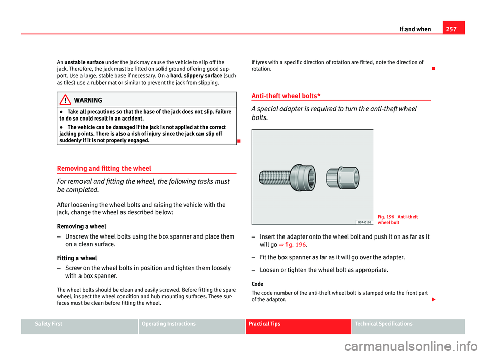
A special adapter is required to turn the anti-theft wheel
bolts.
Fig. 196 Anti-theft
wheel bolt
– Insert the adapter onto the wheel bolt and push it on as far as it
will go ⇒ fig. 196.
– Fit the box spanner as far as it will go over the adapter.
– Loosen or tighten the wheel bolt as appropriate.
Code
The code number of the anti-theft wheel bolt is stamped onto the front part
of the adaptor.
Safety FirstOperating InstructionsPractical TipsTechnical Specifications