Seat Ibiza ST 2016 Manual Online
Manufacturer: SEAT, Model Year: 2016, Model line: Ibiza ST, Model: Seat Ibiza ST 2016Pages: 252, PDF Size: 5.56 MB
Page 81 of 252
Self-help
Check the condition of the wiper blades regu-
l arly
. If
the wipers scrape across the glass ,
they should be changed if they are damaged,
or cleaned if they are dirty ››› .
If thi
s doe
s not produce the desired results,
the setting angle of the windscreen wiper
arms might be incorrect. They should be
checked by a specialised workshop and cor-
rected if necessary. WARNING
Do not drive unless you have good visibility
through al l
windows!
● Clean the windscreen wiper blades and all
windows
regularly.
● The wiper blades should be changed once
or twice a y
ear. CAUTION
● Damaged or dir ty
windscreen wipers could
scratch the glass.
● Never use fuel, nail varnish remover, paint
thinner or similar pr
oducts to clean the win-
dows. This could damage the windscreen
wiper blades.
● Never move any windscreen wiper by hand.
This cou
ld cause damage.
● To prevent damage to the bonnet and the
windsc
reen wiper arms, the latter should only
be lifted off the windscreen when in service
position. Note
● The winds c
reen wiper arms can be moved
to the service position only when the bonnet
is properly closed.
● You can also use the service position, for
exampl
e, if you want to fix a cover over the
windscreen in the winter to keep it clear of
ice. Towing or tow-starting
Notes Read the additional information carefully
› ›
›
p
age 51
Please observe the following points if you
use a tow rope:
Notes for the driver of the towing vehicle
– Move the vehicle slowly until the cable is
taut. Then ac
celerate gradually.
– Begin and change gears cautiously. If you
are driving an aut
omatic vehicle, accelerate
gently.
– Remember that the brake servo and power
steering ar
e not working in the vehicle you
are towing. Brake sooner than normal and
pressing the pedal gently. Notes for the driver of the towed vehicle
– Ensure that the tow rope remains taut at all
times when to
wing.
Towing vehicles with an automatic gearbox
● Put the selector lever into position “N”.
● Do not drive faster than 50 km/h (31 mph).
● Do not tow further than 50 km.
● If a breakdown vehicle is used, the vehicle
must be t
owed with the front wheels raised. WARNING
If the vehicle has no electrical power, the
brake light s, t
urn signals and all other lights
will no longer function. Do not have the vehi-
cle towed away. Failure to follow this instruc-
tion could result in an accident. WARNING
Vehicle handling and braking capacity
chan g
e considerably during towing. Please
observe the following instructions to mini-
mise the risk of serious accidents and injury:
● As the driver of the vehicle being towed:
– You should depr
ess the brake much hard-
er as the brake servo does not operate.
Pay the utmost attention to avoid crash-
ing into the towing vehicle.
– More strength is required at the steering
wheel as the power steering does not op-
erate when the engine is switched off. » 79
Technical data
Advice
Operation
Emergencies
Safety
Page 82 of 252
Emergencies
●
As the driver of the t
owing vehicle:
– Accelerate with particular care and cau-
tion.
– Avoid sudden braking and manoeuvres.
– Brake earlier than usual and more
smoothly. CAUTION
When tow-starting, fuel could enter the cata-
lytic conv
erter and damage it. Note
● Obser v
e legal requirements when towing or
tow-starting.
● Switch on the hazard warning lights of both
vehicle
s. However, observe any regulations
to the contrary.
● For technical reasons, vehicles with an au-
tomatic g
earbox must not be tow-started.
● If there is no lubricant in the gearbox as the
resu
lt of a fault, you must raise the driven
wheels while the vehicle is being towed.
● If the vehicle has to be towed more than
50 km (30 miles), the fr
ont wheels should be
raised during towing, and towing should be
carried out by a qualified person.
● The steering wheel is locked when the vehi-
cle ha
s no electrical power. The vehicle must
then be towed with the front wheels raised.
Towing should be carried out by a qualified
person. ●
The towline anc hor
age should always be
kept in the vehicle. Towline anchorages
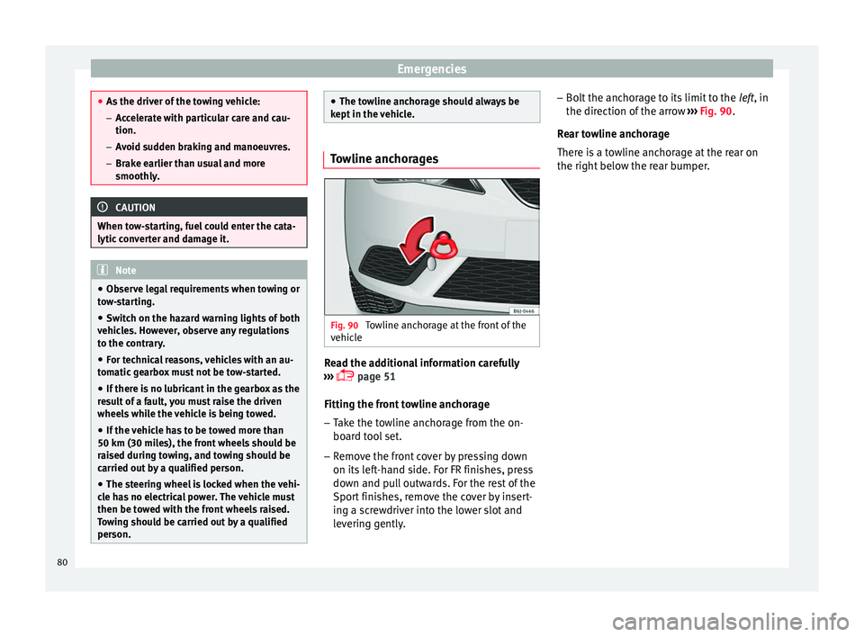
Fig. 90
Towline anchorage at the front of the
v ehic
le Read the additional information carefully
› ›
›
p
age 51
Fitting the front towline anchorage
– Take the towline anchorage from the on-
board too
l set.
– Remove the front cover by pressing down
on its left
-hand side. For FR finishes, press
down and pull outwards. For the rest of the
Sport finishes, remove the cover by insert-
ing a screwdriver into the lower slot and
levering gently. –
Bolt the anchor
age to its limit to the left, in
the direction of the arrow ››› Fig. 90.
Rear towline anchorage
There is a towline anchorage at the rear on
the right below the rear bumper. 80
Page 83 of 252
Fuses and bulbs
Fuses and bulbs F u
se s
Intr
oduction Due to the constant updating of vehicles,
fuse a
s
signments based on equipment and
the use of the same fuse for various electrical
components, it is not possible to provide an
up-to-date summary of the fuse positions for
the electrical components at the time this
manual was printed. For detailed information
about the fuse positions, please consult a
technical service.
In general, a fuse can be assigned to various
electrical components. Likewise, an electrical
component can be protected by several
fuses.
Only replace fuses when the cause of the
problem has been solved. If a newly inserted
fuse blows after a short time, you must have
the electrical system checked by a special-
ised workshop as soon as possible. WARNING
The high voltages in the electrical system can
give serious el
ectrical shocks, causing burns
and even death!
● Never touch the electrical wiring of the igni-
tion system. ●
Take c ar
e not to cause short circuits in the
electrical system. WARNING
Using unsuitable fuses, repairing fuses or
bridgin g a curr ent
circuit without fuses can
cause a fire and serious injury.
● Never use a fuse with a higher value. Only
replac
e fuses with a fuse of the same amper-
age (same colour and markings) and size.
● Never repair a fuse.
● Never replace a fuse by a metal strip, staple
or similar
. CAUTION
● To prev ent
damage to the vehicle's electric
system, before replacing a fuse always turn
off the ignition, the lights and all electrical
elements and remove the key from the igni-
tion.
● If you replace a fuse with higher-rating
fuse, y
ou could cause damage to another part
of the electrical system.
● Protect the fuse boxes when open to pre-
vent the entry
of dust or humidity as they can
damage the electrical system.
● Always carefully remove the fuse box cov-
ers and refit
them correctly to avoid problems
with your vehicle. Note
● One component m a
y have more than one
fuse.
● Several components may run on a single
fuse.
● In the v
ehicle, there are more fuses than
those indicated in thi
s chapter. These should
only be changed by a specialised workshop.
● Positions not containing a fuse do not ap-
pear in the fol
lowing tables.
● Some of the equipment listed in the tables
below pertain on
ly to certain versions of the
model or are optional extras.
● Please note that the above lists, while cor-
rect at the time of
printing, are subject to
change. Fuses to the left of the instrument
p
anel Read the additional information carefully
› ›
›
p
age 44
Only replace fuses with a fuse of the same
amperage (same colour and markings) and
size.
Control box 1
No.Consumer/Amps
1Left lights40
2Central locking40» 81
Technical data
Advice
Operation
Emergencies
Safety
Page 84 of 252
EmergenciesNo.Consumer/Amps
3Power C63 (30 Power)30
4PTC Relay (Engine glow)50
5Left pillar connector A pin 22 (motor
for closing window on driver's side)30
6For closing back left window (motor)30
7Horn20
9Panoramic roof30
10Active suspension7.5
11Headlight washer system relay30
12MIB display5
13(RL-15) SIDO Kl.15 supply (inputs 29
and 55)30
14
Removing ignition key, diagnostics,
headlight lever (flashers), switching
on dipped /side beams (rotating
lights)
7.5
15Air and heat control (supply)7.5Automatic gearbox lever
16Instrument panel5
17Dwa Sensor, Alarm horn7.5
23Dual windscreen cleaner pump7.5
24Engine heater, heating control box
(supply)30
2612V Relay socket20
No.Consumer/Amps
27Rear window wiper motor15
28Lighter20
29Airbag control unit, airbag deactiva-
tion warning lamp10
30
Reverse, Mirror joysticks, RKA, switch-
ing on heated seats, int. pressure A.C,
heating A.C. controls (supply), electro-
chromic mirror, PDC control, switching
on front and rear fog lights (rotating
lights).
7.5
31Petrol gauge5
32
AFS headlights, headlight regulator
(signal and adjustment), LWR Cent, di-
agnostics, front headlight lever
(switch on), Dimmer (headlight adjust-
ment)
7.5
33Start-Stop relay, clutch sensor5
34Heated jets5
35Soundaktor control feed, GRA feed,
Kühlerlüfter central feed5
36Heated seats10
37Additional diagnostics10
38Right hand lights A/66 feed40
39ABS Pump (rear battery)40
41Heated rear window30
42Passenger side window controls30
No.Consumer/Amps
43Rear right window control30
44Reversing camera10
45Windscreen wiper feed lever, diagnos-
tics10
46Additional electric socket for luggage
compartment20
47ABS Ventil (rear battery)25
49
EKP TDI relay (fuel pump feed)30
EKP MPI relay (fuel pump feed)20
TFSI pump gauge control15
50Multimedia Radio (power supply)20
51Heated mirrors10
53Rain sensor5
5430 ZAS (ignition switch)5
55Heated seats10
Control box 2
No.Consumer/Amps
1Lambda sensors15
2
Vacuum pump motor20
Pre-wired motor (coolant pump, varia-
ble valve distributor, active carbon
solenoid valve filter, pressure valve,
secondary air inlet valve)
10
82
Page 85 of 252
Fuses and bulbs
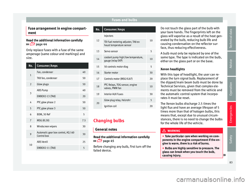
Fuse arrangement in engine compart-
ment Read the additional information carefully
›››
p
age 44
Only replace fuses with a fuse of the same
amperage (same colour and markings) and
size.
No.Consumer/Amps
1Fan, condenser40
TK8 fan, condenser50
2Glow plugs50
3ABS Pump40
EMBOX2-13 (TA8)20
4PTC glow phase 250
5PTC glow phase 350
6BDM, 30 ReF5
7MSG (KL30)7.5
8Windscreen wipers30
9Automatic gear box control, AQ 160
Control box30
10ABS Ventil25
EMBOX2-11 (TA8)5
No.Consumer/Amps
12
Injectors
10TDI fuel metering adjuster, TA8 ex-
haust temperature sensor
13Servo sensor5
14coolant pump high/low temperature,
gauge (relay EKP)10
1550 controls motor diag5
16Starter motor30
17Controls motor (MSG KL87)20
18PTC Relays, TOG sensor, engine
valves, PWM fan10
19Interior AUX Fuses30
20Glow plug relay, Heizrohr5
Ignition coil20 Changing bulbs
Gener al
not
es Read the additional information carefully
› ›
›
p
age 45
Before changing any bulb, first turn off the
failed device. Do not touch the glass part of the bulb with
your bare h
ands. The fingerprints left on the
glass will vaporise as a result of the heat gen-
erated by the bulb, reducing bulb life and
causing condensation on the reflector sur-
face, thus reducing effectiveness.
A bulb must only be replaced by one of the
same type. The type is indicated on the bulb,
either on the glass part or on the base.
Xenon headlights
With this type of headlight, the user can re-
place the turn signal bulb. Replacement of
the dipped/main beam bulb must be done by
Technical Services, given that complex ele-
ments must be removed from the vehicle and
the automatic control system that incorpo-
rates it must be reset.
The Xenon bulbs discharge 2.5 times the
light flux and have an average lifespan of 5
times more than that of halogen bulbs, this
means that, except due to unusual circum-
stances, there is no need to change the bulbs
for the whole life of the vehicle. WARNING
● Take p ar
ticular care when working on com-
ponents in the engine compartment if the en-
gine is warm, there is a risk of burns.
● Bulbs are highly sensitive to pressure. The
glass
can break when you touch the bulb,
causing injury. » 83
Technical data
Advice
Operation
Emergencies
Safety
Page 86 of 252
Emergencies
●
The high vo lt
age element of gas discharge
bulbs* (xenon light) must be handled correct-
ly. Otherwise, there is a risk of death.
● When changing bulbs, please take care not
to injure y
ourself on sharp parts in the head-
light housing. CAUTION
● Remov e the ignition k
ey before working on
the electric system. Otherwise, a short circuit
could occur.
● Switch off the lights or parking lights be-
fore y
ou change a bulb. For the sake of the environment
Please ask your specialist retailer how to dis-
pose of u sed b
ulbs in the proper manner. Note
● Depending on w e
ather conditions (cold or
wet), the front lights, the fog lights, the tail
lights and the turn signals may be temporari-
ly misted. This has no influence on the useful
life of the lighting system. By switching on
the lights, the area through which the beam
of light is projected will quickly be demisted.
However, the edges may continue to be mis-
ted.
● Please check at regular intervals that all
lighting (espec
ially the exterior lighting) on
your vehicle is functioning properly. This is not only in the interest of your own safety,
but a
l
so that of all other road users.
● Before changing a bulb, make sure you
have the corr
ect new bulb.
● Do not touch the glass part of the bulb with
your bare h
ands, use a cloth or paper towel
instead. The residue left by the fingerprints
would vaporise as a result of the heat gener-
ated by the bulb, they will be deposited on
the reflector and will impair its surface. Single headlight bulb change
P o
sition of
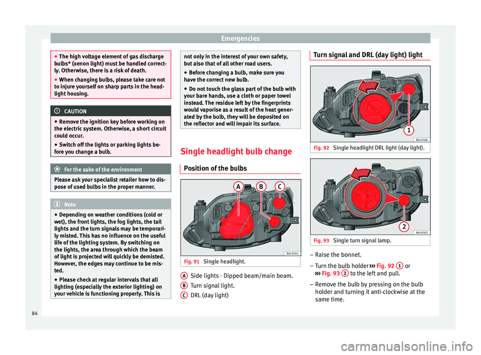
the bulbs Fig. 91
Single headlight. Side lights - Dipped beam/main beam.
T
urn s
ignal
light.
DRL (day light)
A B
C Turn signal and DRL (day light) light
Fig. 92
Single headlight DRL light (day light). Fig. 93
Single turn signal lamp. –
Raise the bonnet.
– Turn the bulb holder ››
›
Fig. 92
1 or
› ›
›
Fig. 93
2 to the left and pull.
– Remove the bulb by pressing on the bulb
ho l
der and t urnin
g it anti-clockwise at the
same time.
84
Page 87 of 252
Fuses and bulbs
– Ins
tal
lation involves all of the above steps
in reverse sequence.
Dipped/main beam headlights and
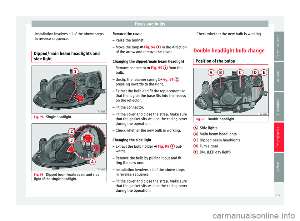
side light Fig. 94
Single headlight. Fig. 95
Dipped beam/main beam and side
light of
the s in
gle headlight. Remove the cover
– Raise the bonnet.
– Move the loop ›
››
Fig. 94
1 in the direction
of the arr
ow and r
emove the cover.
Changing the dipped/main beam headlight – Remove connector ››› Fig. 95
3 from the
b u
lb
.
– Unclip the retainer spring ››› Fig. 95
2 pressing inwards to the right.
– Extract the bulb and fit the replacement so
th at
the lug on the b a
se fits into the recess
on the reflector.
– Fit the connector.
– Fit the cover and close the strap. Make sure
that the ga
sket sits well on the casing cover
during the operation.
– Check whether the new bulb is working.
Changing the s
ide light
– Extract the bulb holder ››› Fig. 95
4 out-
w ar
ds.
– R
emove the bulb by pulling it out and fit-
ting the new one.
– Inst
allation involves all of the above steps
in reverse sequenc
e.
– Fit the cover and close the strap. Make sure
that the ga
sket sits well on the casing cover
during the operation. –
Check whether the new bu
lb is working.
Double headlight bulb change Position of
the bulbs Fig. 96
Double headlight. Side lights
M
ain be
am hea
dlights
Dipped beam headlights
Turn signal
DRL (LED day light)
A B
C
D
E
85
Technical data
Advice
Operation
Emergencies
Safety
Page 88 of 252
Emergencies
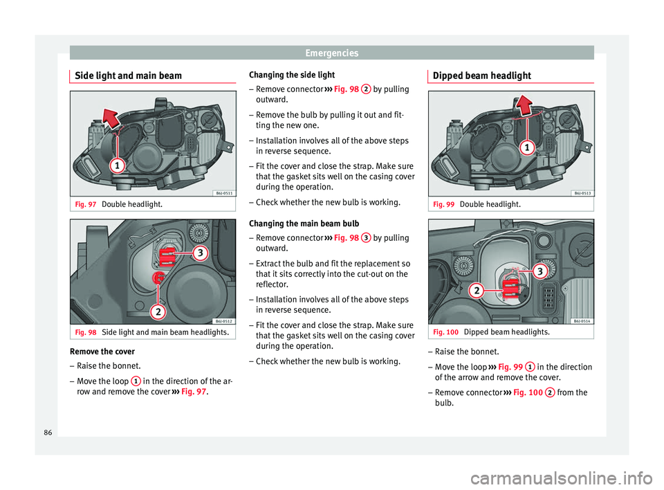
Side light and main beam Fig. 97
Double headlight. Fig. 98
Side light and main beam headlights. Remove the cover
– Raise the bonnet.
– Move the loop 1 in the direction of the ar-
r o
w and r emo
ve the cover ››› Fig. 97. Changing the side light
– Remove connector ››› Fig. 98
2 by pulling
outw ar
d.
– Remo
ve the bulb by pulling it out and fit-
ting the new one.
– Inst
allation involves all of the above steps
in reverse sequenc
e.
– Fit the cover and close the strap. Make sure
that the ga
sket sits well on the casing cover
during the operation.
– Check whether the new bulb is working.
Changing the m
ain beam bulb
– Remove connector ››› Fig. 98
3 by pulling
outw ar
d.
– Extr act
the bulb and fit the replacement so
that it s
its correctly into the cut-out on the
reflector.
– Installation involves all of the above steps
in reverse sequenc
e.
– Fit the cover and close the strap. Make sure
that the ga
sket sits well on the casing cover
during the operation.
– Check whether the new bulb is working. Dipped beam headlight
Fig. 99
Double headlight. Fig. 100
Dipped beam headlights. –
Raise the bonnet.
– Move the loop ››
›
Fig. 99
1 in the direction
of the arr
ow and r
emove the cover.
– Remove connector ››› Fig. 100
2 from the
b u
lb
.
86
Page 89 of 252
Fuses and bulbs
– Unc lip the r
etainer s
pring ››› Fig. 100 3 pressing inwards to the right.
– Extract the bulb and fit the replacement so
th at
the lug on the b a
se fits into the recess
on the reflector.
– Fit the connector.
– Fit the cover and close the strap. Make sure
that the ga
sket sits well on the casing cover
during the operation.
– Check whether the new bulb is working.
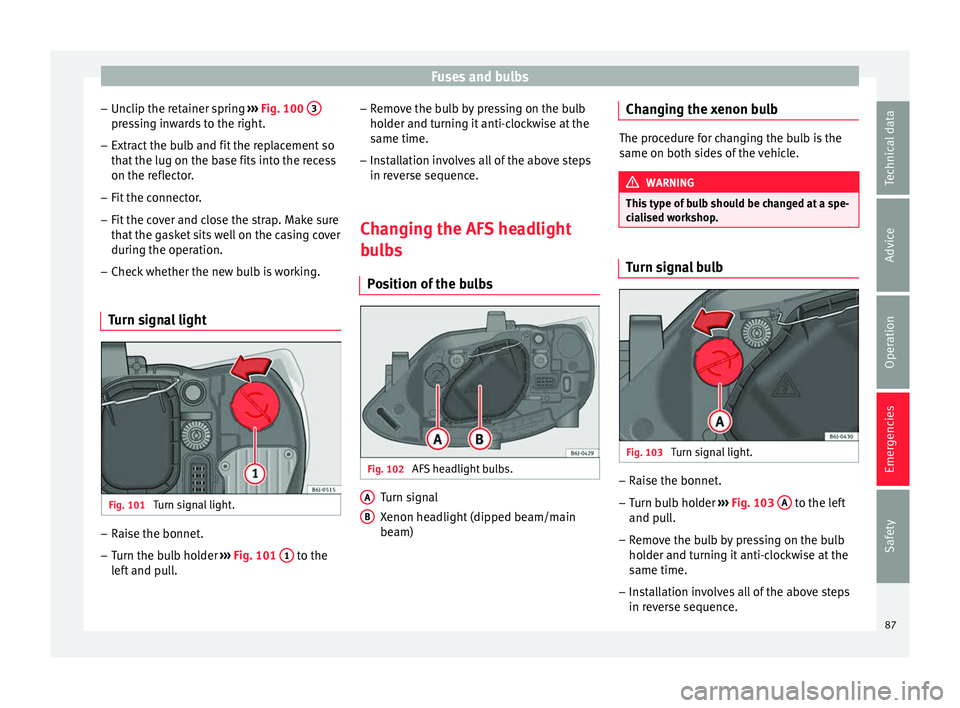
Turn signal light Fig. 101
Turn signal light. –
Raise the bonnet.
– Turn the bulb holder ››
›
Fig. 101
1 to the
l ef t
and p
ull. –
Remove the b
ulb by pressing on the bulb
holder and turning it anti-clockwise at the
same time.
– Installation involves all of the above steps
in reverse sequenc
e.
Changing the AFS headlight
bulb
s
Position of the bulbs Fig. 102
AFS headlight bulbs. Turn signal
X
enon he
adlight
(dipped beam/main
beam)
A B Changing the xenon bulb
The procedure for changing the bulb is the
same on both side
s
of the vehicle. WARNING
This type of bulb should be changed at a spe-
cia li
sed workshop. Turn signal bulb
Fig. 103
Turn signal light. –
Raise the bonnet.
– Turn bulb holder ››
›
Fig. 103
A to the left
and p u
ll
.
– Remove the bulb by pressing on the bulb
holder and turnin
g it anti-clockwise at the
same time.
– Installation involves all of the above steps
in reverse sequenc
e.
87
Technical data
Advice
Operation
Emergencies
Safety
Page 90 of 252
Emergencies
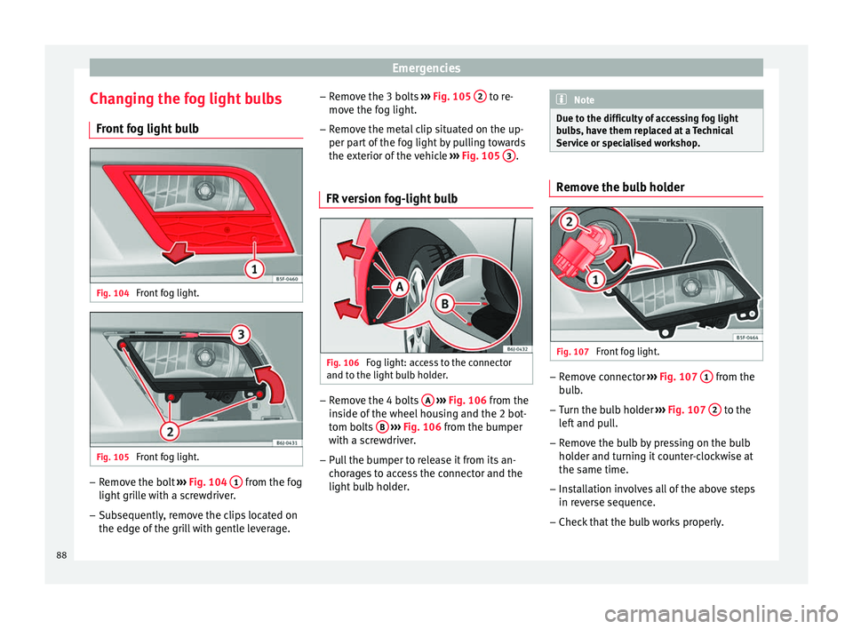
Changing the fog light bulbs Fr ont
fog light
bulbFig. 104
Front fog light. Fig. 105
Front fog light. –
Remove the bolt ››
›
Fig. 104
1 from the fog
light gri
ll
e with a screwdriver.
– Subsequently, remove the clips located on
the edge of the gril
l with gentle leverage. –
Remove the 3 bo
lts ››› Fig. 105 2 to re-
mo v
e the f og light
.
– Remove the metal clip situated on the up-
per part of
the fog light by pulling towards
the exterior of the vehicle ››› Fig. 105 3 .
FR version fog-light bulb Fig. 106
Fog light: access to the connector
and t o the light
bu
lb holder. –
Remove the 4 bolts A
› ›
› Fig. 106 fr
om the
inside of the wheel housing and the 2 bot-
tom bolts B
› ›
› Fig. 106 fr
om the bumper
with a screwdriver.
– Pull the bumper to release it from its an-
chorage
s to access the connector and the
light bulb holder. Note
Due to the difficulty of accessing fog light
bul b
s, have them replaced at a Technical
Service or specialised workshop. Remove the bulb holder
Fig. 107
Front fog light. –
Remove connector ››
›
Fig. 107
1 from the
b u
lb
.
– Turn the bulb holder ››› Fig. 107
2 to the
l ef
t and p
ull.
– Remove the bulb by pressing on the bulb
holder and turnin
g it counter-clockwise at
the same time.
– Installation involves all of the above steps
in reverse sequenc
e.
– Check that the bulb works properly.
88