turn Seat Leon SC 2017 Owner's Guide
[x] Cancel search | Manufacturer: SEAT, Model Year: 2017, Model line: Leon SC, Model: Seat Leon SC 2017Pages: 332, PDF Size: 7.25 MB
Page 50 of 332
The essentials
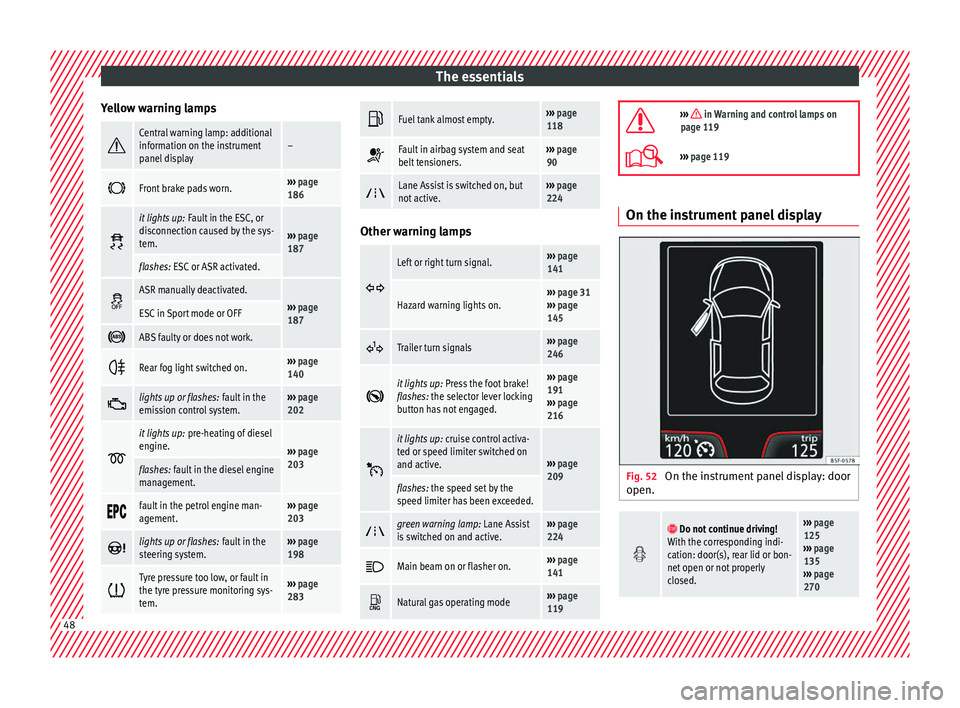
Yellow warning lamps Central warning lamp: additional
information on the instrument
panel display–
Front brake pads worn.›››
page
186
it lights up:
Fault in the ESC, or
disconnection caused by the sys-
tem.
››› page
187
flashes: ESC or ASR activated.
ASR manually deactivated.›››
page
187ESC in Sport mode or OFF
ABS faulty or does not work.
Rear fog light switched on.›››
page
140
lights up or flashes:
fault in the
emission control system.››› page
202
it lights up:
pre-heating of diesel
engine.
››› page
203
flashes: fault in the diesel engine
management.
fault in the petrol engine man-
agement.›››
page
203
lights up or flashes:
fault in the
steering system.››› page
198
Tyre pressure too low, or fault in
the tyre pressure monitoring sys-
tem.›››
page
283
Fuel tank almost empty.›››
page
118
Fault in airbag system and seat
belt tensioners.›››
page
90
Lane Assist is switched on, but
not active.›››
page
224 Other warning lamps
Left or right turn signal.›››
page
141
Hazard warning lights on.››› page 31
››› page
145
Trailer turn signals›››
page
246
it lights up:
Press the foot brake!
flashes: the selector lever locking
button has not engaged.››› page
191
››› page
216
it lights up:
cruise control activa-
ted or speed limiter switched on
and active.
››› page
209
flashes: the speed set by the
speed limiter has been exceeded.
green warning lamp: Lane Assist
is switched on and active.›››
page
224
Main beam on or flasher on.›››
page
141
Natural gas operating mode›››
page
119
››› in Warning and control lamps on
page 119
››› page 119 On the instrument panel display
Fig. 52
On the instrument panel display: door
open.
Do not continue driving!
With the corresponding indi-
cation: door(s), rear lid or bon-
net open or not properly
closed.››› page
125
››› page
135
››› page
270 48
Page 54 of 332

The essentials
Air conditioning Ho w doe
s
Climatronic* work? Fig. 57
In the centre console: Climatronic con-
tro l
s To switch a specific function on, press the ap-
pr
opri
at
e button. Press the button again to
switch off the function. The LED on each control lights up to indicate
that the r
espective function of a control has
been switched on.
1TemperatureThe left and right sides can be adjusted separately: Turn the control to adjust the temperature
2FanThe power of the fan is automatically adjusted. The fan is also adjusted manually by turning the control.
3Air distribution
The airflow adjusts automatically for comfort. You can also switch it on manually using the buttons 3.
: The air is directed at the chest of driver and passengers by the dash panel air vents.
: Air distribution to footwells.
: Upward air distribution.52
Page 55 of 332
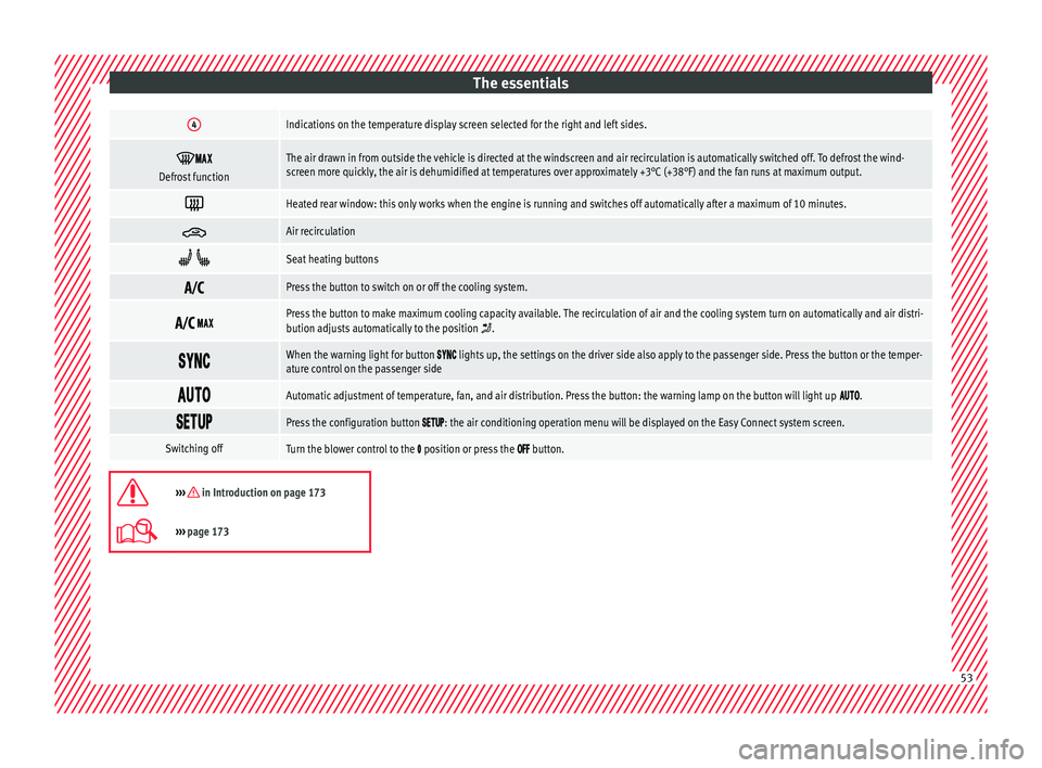
The essentials4Indications on the temperature display screen selected for the right and left sides.
Defrost functionThe air drawn in from outside the vehicle is directed at the windscreen and air recirculation is automatically switched off. To defrost the wind-
screen more quickly, the air is dehumidified at temperatures over approximately +3°C (+38°F) and the fan runs at maximum output.
Heated rear window: this only works when the engine is running and switches off automatically after a maximum of 10 minutes.
Air recirculation
Seat heating buttons
Press the button to switch on or off the cooling system.
Press the button to make maximum cooling capacity available. The recirculation of air and the cooling system turn on automatically and air distri-
bution adjusts automatically to the position .
When the warning light for button lights up, the settings on the driver side also apply to the passenger side. Press the button or the temper-
ature control on the passenger side
Automatic adjustment of temperature, fan, and air distribution. Press the button: the warning lamp on the button will light up .
Press the configuration button : the air conditioning operation menu will be displayed on the Easy Connect system screen.
Switching offTurn the blower control to the position or press the button.
››› in Introduction on page 173
›››
page 173 53
Page 56 of 332
The essentials
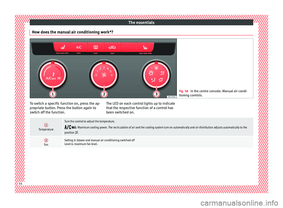
How does the manual air conditioning work*? Fig. 58
In the centre console: Manual air condi-
tioning c ontr
ols. To switch a specific function on, press the ap-
pr
opri
at
e button. Press the button again to
switch off the function. The LED on each control lights up to indicate
that the r
espective function of a control has
been switched on.
1Temperature
Turn the control to adjust the temperature.
: Maximum cooling power. The recirculation of air and the cooling system turn on automatically and air distribution adjusts automatically to the
position .
2FanSetting 0: blower and manual air conditioning switched off
Level 6: maximum fan level. 54
Page 58 of 332
The essentials
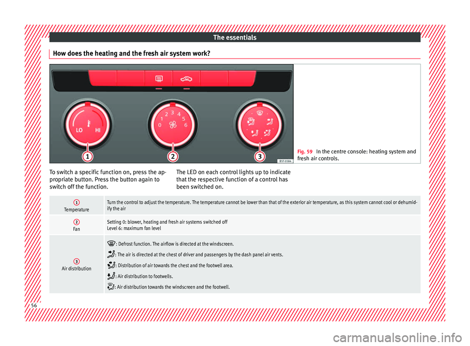
How does the heating and the fresh air system work? Fig. 59
In the centre console: heating system and
fre sh air c
ontrols. To switch a specific function on, press the ap-
pr
opri
at
e button. Press the button again to
switch off the function. The LED on each control lights up to indicate
that the r
espective function of a control has
been switched on.
1TemperatureTurn the control to adjust the temperature. The temperature cannot be lower than that of the exterior air temperature, as this system cannot cool or dehumid-
ify the air
2FanSetting 0: blower, heating and fresh air systems switched off
Level 6: maximum fan level
3Air distribution
: Defrost function. The airflow is directed at the windscreen.
: The air is directed at the chest of driver and passengers by the dash panel air vents.
: Distribution of air towards the chest and the footwell area.
: Air distribution to footwells.
: Air distribution towards the windscreen and the footwell.
56
Page 60 of 332
The essentials
Fluid Level control Fi l
lin
g capacities
Tank level
Petrol and diesel
engines50 l, of which, approx. 7 l reserveVehicles with all-wheel-drive :
55 l, of which, approx. 8.5 l re- serve
Natural gas en-
ginea)approx. 15 kg
a)
The capacity depends on the efficacy and characteristics of
the natural gas pumps. The capacity indicated is based on a
minimum loading pressure of 200 bar.
Capacity of the windscreen washer fluid container
Versions without
headlight washer
systemapprox. 3 litres
Versions with
headlight washer
systemapprox. 5 litres Fuel
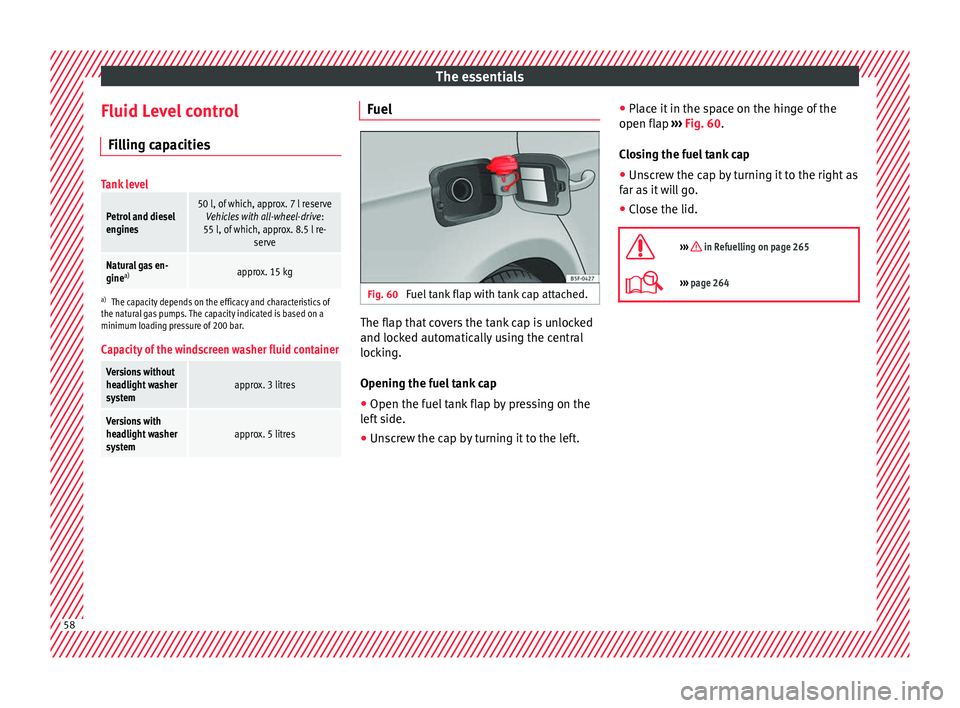
Fig. 60
Fuel tank flap with tank cap attached. The flap that covers the tank cap is unlocked
and loc
k
ed aut
omatically using the central
locking.
Opening the fuel tank cap
● Open the fuel tank flap by pressing on the
left
side.
● Unscrew the cap by turning it to the left. ●
Place it
in the space on the hinge of the
open flap ››› Fig. 60.
Closing the fuel tank cap ● Unscrew the cap by turning it to the right as
far as
it will go.
● Close the lid.
››› in Refuelling on page 265
››› page 264 58
Page 66 of 332
The essentials
● Rep
l
ace the cover again or close the fuse
box lid.
Bulbs Bul
bs (12 V) Note: Depending on the level of equipment
fitt
ed in the
vehicle, LEDs may be used for
part or all of the interior and/or exterior light-
ing. LEDs have an estimated life that exceeds
that of the vehicle. If an LED light fails, go to
an authorised workshop for its replacement.
Light source used for each function
Halogen headlights.Type
Daytime running light/side
lightP21W SLL
Dipped beam headlightsH7 LL
Main beam headlightsH7 LL
Turn signalPY21W LL
Full-LED main headlightsType
No bulbs may be replaced. All functions are with LEDs
Front fog lightType
Fog/cornering lights*H8
Rear lightsType
Brake light/tail lightP21W LL
Side lights2x W5W LL
Turn signalPY21W LL
Retro fog lightH21W
Reverse lightsP21W LL
LED rear lightsType
Reverse lightsW16W
The remaining functions work with LEDs
›››
page 103 Action in the event of a punc-
t
ur
e
Wh
at to do first ●
Park the vehicle on a horizontal surface
and in a s af
e p
lace as far away from traffic as
possible.
● Apply the handbrake.
● Switch on the hazard warning lights.
● Manual gearbox: select the 1s
t gear.●
Automatic ge
arbox: Move the selector lever
to position P.
● If you are towing a trailer, unhitch it from
your v
ehicle.
● Have the vehicle tool kit ›››
page 95
and the spare wheel* ready
››› page 286.
● Observe the applicable legislation for each
countr
y (reflective vest, warning triangles,
etc.).
● All occupants should leave the vehicle and
wait in a s
afe place (for instance behind the
roadside crash barrier). WARNING
● Alw a
ys observe the above steps and pro-
tect yourself and other road users.
● If you change the wheel on a slope, block
the wheel on the oppo
site side of the car with
a stone or similar to prevent the vehicle from
moving. 64
Page 67 of 332

The essentials
Repairing a tyre with the anti-punc-
t ur
e k
it Fig. 69
Standard representation: contents of
the anti-p u
nct
ure kit. The anti-puncture kit is located under the
floor p
anel
in the lug
gage compartment.
Sealing the tyre
● Unscrew the tyre valve cap and insert. Use
the ›››
Fig. 69 1 tool to remove the insert.
Pl ac
e it
on a clean surface.
● Shake the tyre sealant bottle vigorously
›››
Fig. 69 10 .
● Screw the inflator tube ››
›
Fig. 69 3 into
the se al
ant
bottle. The bottle's seal will break
automatically. ●
Remov
e the lid from the filling tube
››› Fig. 69 3 and screw the open end of the
t ube int
o the ty
re valve.
● With the tyre sealant bottle upside down,
fill
the tyre with the contents of the sealant
bottle.
● Remove the bottle from the valve.
● Place the insert back into the tyre valve us-
ing the too
l ››› Fig. 69 1 .
Infl atin
g the ty
re
● Screw the compressor tyre inflator tube
›››
Fig. 69 5 into the tyre valve.
● Check that the air bleed screw is closed
› ›
›
Fig. 69 7 .
● Start the engine and leave it running.
● Insert the connector ››
›
Fig. 69 9 into the
v ehic
l
e's 12-volt socket ›››
page 159.
● Turn the air compressor on with the ON/OFF
switc
h ››› Fig. 69 8 .
● Keep the air compressor running until it
r e
ac
hes 2.0 to 2.5 bar
(29-36 psi/200-250 kPa). A maximum of 8
minutes.
● Disconnect the air compressor.
● If it does not reach the pressure indicated,
uns
crew the tyre inflator tube from the valve.
● Move the vehicle 10m so that the sealant is
dis trib
uted throughout the tyre. ●
Scr ew the c
ompressor tyre inflator into the
valve.
● Repeat the inflation process.
● If the indicated pressure still cannot be
reac
hed, the tyre is too badly damaged. Stop
and request assistance from an authorised
technician.
● Disconnect the air compressor. Unscrew
the tyre infl
ator tube from the tyre valve.
● When the tyre pressure is between 2.5 and
2.0 bars, c
ontinue driving without exceeding
80 km/h (50 mph).
● Check the pressure again after 10 minutes
›››
page 97.
››› in TMS (Tyre Mobility System)* on
page 95
››› page 95 65
Page 69 of 332
The essentials
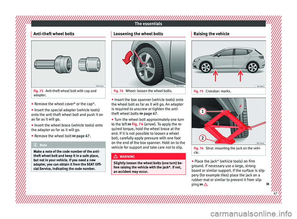
Anti-theft wheel bolts Fig. 73
Anti-theft wheel bolt with cap and
a d
apt
er. ●
Remove the wheel cover* or the cap*.
● Insert the special adapter (vehicle tools)
ont o the anti-thef
t
wheel bolt and push it on
as far as it will go.
● Insert the wheel brace (vehicle tools) onto
the adapt
er as far as it will go.
● Remove the wheel bolt ›››
page 67 . Note
Make a note of the code number of the anti-
theft wheel
bolt and keep it in a safe place,
but not in your vehicle. If you need a new
adapter, you can obtain it from the SEAT Offi-
cial Service, indicating the code number. Loosening the wheel bolts
Fig. 74
Wheel: loosen the wheel bolts. ●
Insert the box spanner (vehicle tools) onto
the wheel bo
lt
as far as it will go. An adapter
is required to unscrew or tighten the anti-
theft wheel bolts ››› page 67.
● Turn the wheel bolt approximately one turn
to the lef
t ››› Fig. 74 (arrow). To apply the re-
quired torque, hold the wheel brace at the
end. If it is not possible to loosen a wheel
bolt, carefully apply pressure with one foot
on the end of the box spanner. Hold on to the
vehicle for support and take care not to slip. WARNING
Slightly loosen the wheel bolts (one turn) be-
for e r
aising the vehicle with the jack*. If not,
an accident may occur. Raising the vehicle
Fig. 75
Crossbar: marks. Fig. 76
Strut: mounting the jack on the vehi-
c l
e. ●
Place the jack* (vehicle tools) on firm
gr ou
nd. If
necessary use a large, strong
board or similar support. If the surface is slip-
pery (for example tiles) place the jack on a
rubber mat or similar to prevent it from slip-
ping ››› .
» 67
Page 70 of 332

The essentials
● Find the s up
por
t point on the strut (sunken
area) closest to the wheel to be changed
››› Fig. 75.
● Turn the jack*, located below the strut sup-
port point, t
o raise it until tab 1
› ››
Fig. 76
is
below the housing provided.
● Align the jack* so that tab 1 “grips” onto
the hou s
in
g provided on the strut and the
mobile base 2 is resting on the ground. The
b a
se p
late 2 should fall vertically with re-
s pect
t
o the support point 1 .
● Continue turning the jack* until the wheel
i s
s
lightly lifted off the ground. WARNING
● Mak e s
ure that the jack* remains stable. If
the surface is slippery or soft, the jack* could
slip or sink, respectively, with the resultant
risk of injury.
● Only raise the vehicle with the jack* sup-
plied by
the manufacturer. Other vehicles
could slip, with the consequent risk of injury.
● Only mount the jack* on the support points
designed f
or this purpose on the strut, and
always align the jack correctly. If you do not,
the jack* could slip as it does not have an ad-
equate grip on the vehicle: risk of injury!
● The height of the parked vehicle can
chan
ge as a result of variations in tempera-
ture and loading. CAUTION
The vehicle must not be raised on the cross-
bar . On
ly place the jack* on the points de-
signed for this purpose on the strut. Other-
wise, the vehicle may be damaged. Removing and fitting a wheel
Change the wheel after loosening the wheel
bolts
and r
aising the vehicle with the jack.
Taking off the wheel ● Unscrew the wheel bolts using the box
sp anner and p
lace them on a clean surface.
● Take off the wheel.
Putting on the s
pare wheel
When fitting tyres with a compulsory rotation
direction, observe the instructions in
››› page 68.
● Mount the wheel.
● Screw on the wheel bolts in position and
tighten them loosely
with a box spanner.
● Carefully lower the vehicle using the jack*.
● Tighten the wheel bolts in diagonal pairs
usin
g the wheel brace.
The wheel bolts should be clean and turn
easily. Before fitting the spare wheel, inspect
the wheel condition and hub mounting surfa- ces. These surfaces must be clean before fit-
ting the wheel.
T
yres with compulsory direction of ro-
tation A directional tread pattern can be identified
by
the arr
ows on the sidewall that point in
the direction of rotation. Always observe the
direction of rotation indicated when fitting
the wheel to guarantee optimum properties
of this type of tyres with regard to grip,
noises, wear and aquaplaning.
If it is absolutely necessary to fit the spare
tyre* against the direction of rotation, drive
with care as this means the tyre does not of-
fer optimum driving properties. This is of par-
ticular importance when the road surface is
wet.
To return to directional tread tires, replace
the punctured tyre as soon as possible and
restore the obligatory direction of rotation of
all tyres.
Subsequent work ●
Alloy wheels: rep
l
ace the wheel bolt caps.
● Plate wheels: rep l
ace the wheel hubcap
››› page 66.68