turn Seat Leon SC 2017 Repair Manual
[x] Cancel search | Manufacturer: SEAT, Model Year: 2017, Model line: Leon SC, Model: Seat Leon SC 2017Pages: 332, PDF Size: 7.25 MB
Page 142 of 332

Operation
●
Nobody shou
ld be in the way of the panor-
amic sliding sunroof or sun blind, especially
when they are closed without the anti-trap
function.
● The anti-trap function does not prevent fin-
gers
or other parts of the body getting
pinched against the window frame and caus-
ing injury. Note
The anti-trap function is activated if the win-
do ws
and the panoramic sliding sunroof are
closed from the outside of the vehicle using
the ignition key for convenience closing
››› page 137. Lights and visibility
Light s
Side light and dip
ped beam headlight Read the additional information carefully
›› ›
page 30
The driver is personally responsible for the
correct use and adjustment of the lights in all
situations.
Audible warnings to advise the driver that
the lights have not been switched off
If the key is not in the ignition and the driver
door is open, an audible warning signal is
heard in the following cases: this is a remind-
er to turn off the lights.
● When the parking light is on ››
›
page 141.
● When the light switch is in position or
. WARNING
The side lights or daytime running lights are
not bright enough t
o illuminate the road
ahead and to ensure that other road users are
able to see you.
● Always use your dipped beam head lights if
it is
raining or if visibility is poor. WARNING
If the headlights are set too high and not
used c orr
ectly, there is a risk of dazzling or
distracting other road users. This could result
in a serious accident.
● Always make sure that the headlights are
correctly
adjusted. Note
The legal requirements regarding the use of
vehic l
e lights in each country must be ob-
served. Daytime running lights
The daytime running lights consist of individ-
ual
lights, int
e
grated in the front headlights.
With the daylight driving lights on, only these
lights switch on ››› .
The d a
ytime ru
nning lights switch on every
time the ignition is switched on, if the switch
is in positions or , according to the level
of exterior lighting.
When the light switch is in position , a
light sensor automatically switches dipped
beam on and off (including the control and
instrument lighting) or the daytime running
lights depending on the level of exterior
lighting.
140
Page 143 of 332

Lights and visibility
WARNING
● Never driv e w
ith daytime lights if the road
is not well lit due to weather or lighting con-
ditions. Daytime lights do not provide
enough light to illuminate the road properly
or be seen by other road users.
● The rear lights do not come on with the
daytime driv
ing light. A vehicle which does
not have the rear lights on may not be visible
to other drivers in the darkness, in the case
of heavy rain or in conditions of poor visibili-
ty. Turn signal and main beam lever
Read the additional information carefully
› ›
›
page 31
Push the lever all the way down to turn off
the corresponding function.
Convenience turn signals
For the one-touch signalling, when the igni-
tion is switched on, move the lever as far as
possible upwards or downwards and release
the lever. The turn signal will flash three
times.
One-touch signalling is activated and deacti-
vated in the Easy Connect system via the button and the function button SETTINGS >
Lights > One-touch signalling
› ›
›
page 33. In vehicles that do not have the correspond-
ing menu, this
function can be deactivated in
a specialised workshop. WARNING
Improper or lack of use of the turn signals, or
for g
etting to deactivate them can confuse
other road users. This could result in a seri-
ous accident.
● Always give warning when you are going to
chan
ge lane, overtake or when turning, acti-
vating the turn signal in good time.
● As soon as you have finished changing
lane, ov
ertaking or turning, switch the turn
signal off. WARNING
Incorrect use of the headlights may cause ac-
cident s
and serious injury, as the main beam
may distract or dazzle other drivers. Note
● If the c on
venience turn signals are operat-
ing (three flashes) and the other convenience
turn signals are switched on, the active part
stops flashing and only flashes once in the
new part selected.
● The turn signal only works when the igni-
tion is sw
itched on. The hazard warning
lights also work when the ignition is switch-
ed off. ●
If a tr ai
ler turn signal malfunctions, the
control lamp will stop flashing (trailer turn
signals) and the vehicle turn signal will flash
at double speed.
● The main beam headligh
ts can only be
switched on if the dipped beam headlights
are already on.
● In cold or damp weather conditions, the
headlight
s, tail lights and turn signals may
mist up inside temporarily. This is normal and
in no way effects the useful life of the vehicle
lighting system. Automatic dipped beam control
* The automatic dipped beam control is merely
int
ended a
s
an aid and is not able to recog-
nise all driving situations.
When the light switch is in position , the
vehicle lights and the instrument panel and
switch lighting switch on and off automatical-
ly in the following situations ››› in Daytime
ru nnin
g light
s on page 141:
Automatic switching
onAutomatic switching
off
The photo sensor detects
darkness, for example,
when driving through a
tunnel.When adequate lighting is
detected.» 141
Technical data
Advice
Operation
Emergencies
Safety
Page 144 of 332

OperationAutomatic switching
onAutomatic switching
off
The rain sensor detects
rain and activates the
windscreen wipers.When the windscreen wip-
ers have been inactive for
a few minutes.
WARNING
If the road is not well lit and other road users
cannot see the
vehicle well enough or at all,
accidents may occur.
● The automatic dipped beam control ( )
only sw
itches on the dipped beam when
there are no changes in brightness, and not,
for example when it is foggy. Main beam assist*
Main beam assist (Light Assist)
The m
ain be
am a
ssist acts within the limits
of the system and depending on environmen-
tal and traffic conditions. Once switched on,
the system is activated as of a speed of
about 60 km/h (37 mph) and is deactivated
below about 30 km/h (18 mph) ››› .
When the sy s
t
em is activated and the camera
detects other vehicles that may be dazzled,
the main beam is automatically switched off.
Otherwise, the main beam is automatically
switched on.
The main beam assist generally detects illu-
minated areas and deactivates the main beam when passing through a town, for ex-
ample.
Sw
itching the main beam assist on and off
Func-
tionUse
Activate:
– Switch the ignition on and turn the light
switch to position .
– From the base position, move the main
beam and turn signal lever forwards
››› page 141. When the warning lamp
is
displayed on the instrument panel display,
the main beam assist is switched on.
To switch system off:
– Switch off the ignition.
– OR: turn the light switch to a different po-
sition to
››› page 140.
– OR: with main beam on, move the main
beam and turn signal lever backwards.
– OR: move the main beam and turn the
signal lever forwards to manually switch
the main beam on. The main beam assist
will then be deactivated. Malfunctions
The f
o
l
lowing conditions may prevent the
main beam headlight control from turning off
the headlights in time or from turning off al-
together:
● In poorly lit towns with highly reflective
signs.
● Other in
sufficiently lit road users (such as
pedestri
ans or cyclists). ●
On tight bends
and steep slopes (bumps)
and when oncoming vehicles are partially ob-
scured.
● When the drivers of other oncoming vehi-
cle
s (such as a truck) can see over a guard
rail in the centre of the road.
● If the camera is damaged or the power sup-
ply i
s cut off.
● In fog, snow and heavy rain.
● With dust and sand turbulence.
● With loose gravel in the field of vision of
the camera.
● When the fiel
d of vision of the camera is
mist
ed up, dirty or covered by stickers, snow,
ice, etc. WARNING
The convenience features of the main beam
as s
ist should not encourage the taking of
risks. The system is not a replacement for
driver concentration.
● You are always in control of the main beam
and adaptin
g it to the light, visibility and traf-
fic conditions.
● It is possible that the main beam headlight
contro
l does not recognise all driving situa-
tions and is limited under certain circumstan-
ces.
● When the field of vision of the camera is
dirty, c
overed or damaged, operation of the
main beam control may be affected. This also
applies when changes are made to the 142
Page 145 of 332

Lights and visibility
vehicle lighting system, for example, if addi-
tiona
l
headlights are installed. CAUTION
To avoid affecting the operation of the sys-
t em, t ak
e the following points into considera-
tion:
● Clean the field of vision of the camera regu-
larly and m
ake sure it is free of snow and ice.
● Do not cover the field of vision of the cam-
era.
● Check
that the windscreen is not damaged
in the area of
the field of vision of the camera. Note
Main beam and headlight flasher can be
turned on and off m
anually at any time with
the turn signal and main beam lever
››› page 141. Fog lights
Fig. 142
Dash panel: light control. The warning lamps
or also sho
w
, on the
light switch or instrument panel, when the
fog lights are on.
● Switching on front fog lights* : pul
l the
light switch to the first point ››› Fig. 142 1 ,
fr om po
s
itions , or .
● Switching on the rear fog light : com-
pl
etely pull the light switch 2 from position
, or .
● To sw
itch off the fog lights, press the light
switc
h or turn it to position . Note
The rear fog light can dazzle drivers behind
you. Y
ou should use the rear fog light only
when visibility is very poor. For this reason, if
you exceed approximately 60 km/h (38 mph),
the instrument panel will display the follow-
ing warming: Switch off the fog light! Cornering lights*
1) When turning slowly or on very tight bends,
the c
ornerin
g lights
are activated automati-
cally. The cornering lights may be integrated
in the fog lights and are switched on only at
speeds of less than 40 km/h (25 mph).
When reverse gear is engaged, the cornering
lights on both sides of the vehicle switch on,
in order to better illuminate the area for park-
ing.
Function “Coming home” This function may be connected/disconnec-
t
ed thr
ough the r
adio menu. The “Coming
Home” and/or “Leaving Home” delay time
may also be set (default: 30 sec). »1)
This function is not available on vehicles equipped
with f u
ll-LED headlights and bulb fog lights. 143
Technical data
Advice
Operation
Emergencies
Safety
Page 146 of 332

OperationVehicle with
halogen
headlightsIn the “Coming Home” function, the day-
time running lights (DRL), the rear side
lights and the licence plate lights are
turned on.
Vehicle with
full-LED
headlightsIn the “Coming Home” function, the dip-
ped beams and the daytime running
lights (DRL), the rear side lights and the
licence plate lights are switched on.
Automatic* activation of “Coming Home”
For
v
ehicles with a light and rain sensor (rota-
ry light switch in position ).
● Switch off the engine and remove the key
from the ignition w ith the r
otary light switch
in position ›››
page 30.
● The automatic “Coming Home” function is
only activ
e when the light sensor detects
darkness.
● When the car door is opened, the “Coming
Home” lighting come
s on.
Manual “Coming Home” activation
For vehicles with a light and rain sensor (rota-
ry light switch without position ).
● Switch off the engine and remove the key
from the ignition.
● Activ
ate the headlight flashers for approxi-
mately
1 second.
● Activated for any position of the rotary light
switc
h. ●
When the car door is
opened, the “Coming
Home” lighting comes on. The headlights are
turned off 60 seconds after the vehicle door
is opened.
Deactivation
● If no door has been closed, they go out au-
tomatic
ally after 60 seconds.
● After the last door has been closed, the
headlights
will be switched off after the
“Coming Home” delay (as established in the
radio menu) has elapsed.
● On turning the light switch to position
›››
page 30.
● When the ignition is switched on (when
star
ting the engine).
Function “Leaving Home” The “Leaving Home” function is only availa-
b
l
e f
or vehicles with a light and rain sensor
(rotary light switch in position ).
This function may be connected/disconnec-
ted through the radio menu. The “Leaving
Home” function switch-off delay may also be
set (default: 30 sec).
Vehicle with
halogen
headlightsIn the “Leaving Home” function, the day-
time running lights (DRL), the rear side
lights and the licence plate lights are
switched on.
Vehicle with
full-LED
headlightsIn the “Leaving Home” function, the dip-
ped beams, the daytime running lights
(DRL), the rear side lights and the li-
cence plate lights are switched on. Activation
● When the vehicle is unlocked using the re-
mote c ontr
ol.
● The “Leaving Home” function is only activa-
ted when the rot
ary light switch is in position
and the light sensor detects darkness.
Deactivation
● When the “Leaving Home” delay period
ends (def
ault: 30 sec).
● When the vehicle is locked using the re-
mote contr
ol.
● When the light control is switched into a
position other th
an .
● With the ignition is switched on.
144
Page 147 of 332

Lights and visibility
Hazard warning lights Fig. 143
Dash panel: switch for hazard warn-
in g lights. Read the additional information carefully
› ›
›
page 31
The hazard warning lights are used to draw
the attention of other road users to your vehi-
cle in emergencies.
If your vehicle breaks down:
1. Park your vehicle at a safe distance from movin
g traffic.
2. Press the button to switch on the hazard warning lights
››› .
3. Switch the ignition off.
4. Apply the handbrake.
5. For a manual gearbox, engage 1st gear; for an aut
om
atic gearbox, move the gear
lever to P. 6. Use the warning triangle to draw the atten-
tion of other ro
ad users to your vehicle.
7. Always take the vehicle key with you when you le
ave the vehicle.
All turn signals flash simultaneously when
the hazard warning lights are switched on.
The two turn signal turn signal lamps
and the turn signal lamp in the switch will
flash at the same time. The simultaneous
hazard warning lights also work when the ig-
nition is switched off.
Emergency braking warning
If the vehicle brakes suddenly and continu-
ously at a speed of more than 80 km/h (50
mph), the brake light flashes several times
per second to warn the vehicles driving be-
hind. If you continue braking, the hazard
warning lights will come on automatically
when the vehicle comes to a standstill. They
switch off automatically when the vehicle
starts to move again. WARNING
● The risk of
an accident increases if your ve-
hicle breaks down. Always use the hazard
warning lights and a warning triangle to draw
the attention of other road users to your sta-
tionary vehicle.
● Due to the high temperatures that the cata-
lytic con
verter can reach, never park in an
area where the catalytic converter could come into contact with highly inflammable materi-
al
s, f
or example dry grass or spilt petrol. This
could start a fire. Note
● The b atter
y will run down if the hazard
warning lights are left on for a long time,
even if the ignition is switched off.
● The use of the hazard warning lights de-
scribed her
e is subject to the relevant statu-
tory requirements. Parking lights
When the parking light is switched on, (right
or l
ef
t
turn signal), the front side light and
the rear light on the corresponding side of
the vehicle stay lit. The parking lights can on-
ly be activated with the ignition switched off
and the turn signal and main beam lever in
the central position, before being triggered.
Parking light on both sides With the ignition switched off and the light
sw
it
c
h in position , when locking the vehi-
cle from the outside, the parking lights on
both sides of the vehicle light up. In doing
so, only the side lights of both headlights
light up, and additionally the tail lights will
do so partially.
145
Technical data
Advice
Operation
Emergencies
Safety
Page 148 of 332
Operation
Motorway light* The motorway light is available on vehicles
equipped w
ith f
ull-LED lights.
The function is connected/disconnected via
the corresponding Easy Connect system
menu.
● Activation: when going abo
ve 110 km/h
(68 mph) for more than 30 seconds, the dip-
ped beam raises slightly to increase the driv-
er's visibility distance.
● Deactivation: when reduc in
g the speed of
the car below 100 km/h (62 mph), the dip-
ped beam returns to its normal position.
Driving abroad The light beam of the dipped beam lights is
a
symmetric: the s
ide of
the road on which
you are driving is lit more intensely.
When a car that is manufactured in a country
that drives on the right travels to a country
that drives on the left (or vice versa), it is nor-
mally necessary to cover part of the headlight
bulbs with stickers or to change the adjust-
ment of the headlights to avoid dazzling oth-
er drivers.
In such cases, the regulations specify certain
light values that must be complied with for
designated points of the light distribution.
This is known as “Tourist light”. The light distribution that the halogen and
ful
l-LED headlights of the SEAT Leon range
have allows the specific “tourist light” values
to be met without the need for stickers or
changes in the settings. Note
“Tourist light” is only allowed temporarily. If
you ar e p
lanning a long stay in a country that
drives on the other side, you should take the
vehicle to an Authorised Technical Service to
change the headlights. Headlight range control
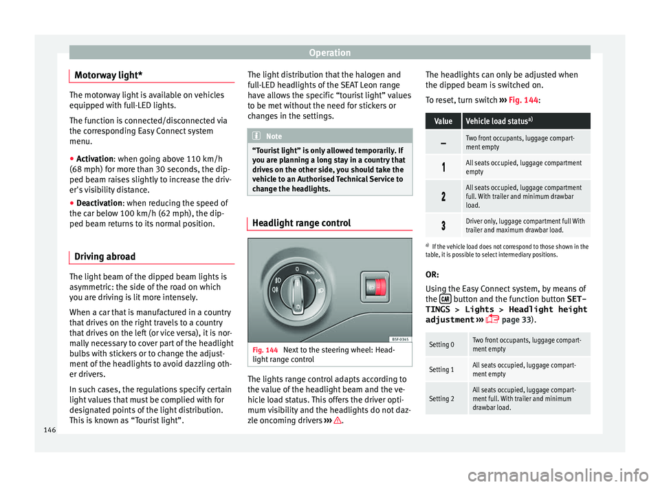
Fig. 144
Next to the steering wheel: Head-
light ran
ge control The lights range control adapts according to
the
v
alue of
the headlight beam and the ve-
hicle load status. This offers the driver opti-
mum visibility and the headlights do not daz-
zle oncoming drivers ››› .The headlights can only be adjusted when
the dip
ped be
am i
s switched on.
To reset, turn switch ››› Fig. 144:
ValueVehicle load status a)
Two front occupants, luggage compart-
ment empty
All seats occupied, luggage compartment
empty
All seats occupied, luggage compartment
full. With trailer and minimum drawbar
load.
Driver only, luggage compartment full With
trailer and maximum drawbar load.
a)
If the vehicle load does not correspond to those shown in the
table, it is possible to select intermediary positions.
OR:
Using the Easy Connect system, by means of
the button and the function button SET-
TINGS > Lights > Headlight height
adjustment
› ›
›
page 33).
Setting 0Two front occupants, luggage compart-
ment empty
Setting 1All seats occupied, luggage compart-
ment empty
Setting 2All seats occupied, luggage compart-
ment full. With trailer and minimum
drawbar load.146
Page 150 of 332
Operation
Visibility S u
n
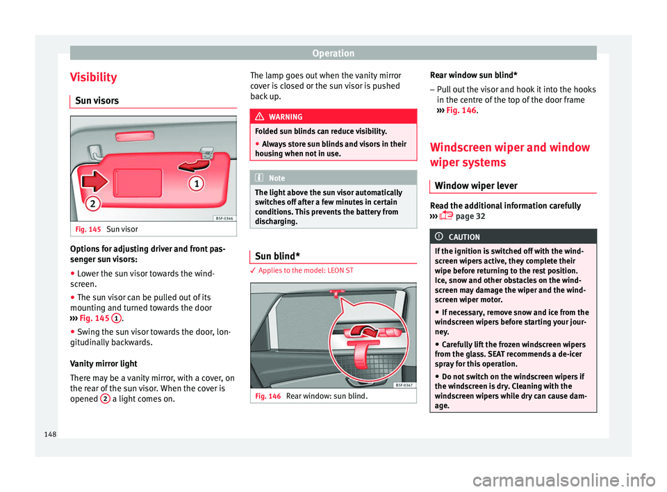
visors Fig. 145
Sun visor Options for adjusting driver and front pas-
sen
g
er s
un visors:
● Lower the sun visor towards the wind-
scr
een.
● The sun visor can be pulled out of its
mounting and t
urned towards the door
››› Fig. 145 1 .
● Swing the sun visor towards the door, lon-
git udin
al
ly backwards.
Vanity mirror light
There may be a vanity mirror, with a cover, on
the rear of the sun visor. When the cover is
opened 2 a light comes on. The lamp goes out when the vanity mirror
c
o
v
er is closed or the sun visor is pushed
back up. WARNING
Folded sun blinds can reduce visibility.
● Always store sun blinds and visors in their
hous in
g when not in use. Note
The light above the sun visor automatically
swit c
hes off after a few minutes in certain
conditions. This prevents the battery from
discharging. Sun blind*
3 App
lies to the model: LEON ST Fig. 146
Rear window: sun blind. Rear window sun blind*
– Pull out the visor and hook it into the hooks
in the c entre of
the top of the door frame
››› Fig. 146.
Windscreen wiper and window
wiper sys
tems
Window wiper lever Read the additional information carefully
› ›
›
page 32 CAUTION
If the ignition is switched off with the wind-
sc r
een wipers active, they complete their
wipe before returning to the rest position.
Ice, snow and other obstacles on the wind-
screen may damage the wiper and the wind-
screen wiper motor.
● If necessary, remove snow and ice from the
winds
creen wipers before starting your jour-
ney.
● Carefully lift the frozen windscreen wipers
from the gla
ss. SEAT recommends a de-icer
spray for this operation.
● Do not switch on the windscreen wipers if
the winds
creen is dry. Cleaning with the
windscreen wipers while dry can cause dam-
age. 148
Page 153 of 332

Lights and visibility
Interior rear vision mirror with manual set-
tin g f
or anti-d
azzle position
● Position the small lever of the lower edge
of the mirror t
o face towards the rear. WARNING
In the event that an automatic anti-dazzle
re ar
vision mirror breaks, an electrolyte fluid
may leak. This could cause irritation to the
skin, eyes and respiratory organs. If you
come into contact with this liquid, it must be
rinsed with large quantities of water. If neces-
sary, get medial help. CAUTION
In the event that an automatic anti-dazzle
re ar
vision mirror breaks, an electrolyte fluid
may leak. This liquid attacks plastic surfaces.
Clean it with a wet sponge as soon as possi-
ble. Note
● If the light inc
ident in the interior rear vi-
sion mirror is obstructed (e.g. with the sun
blind*), the anti-dazzle rear vision mirror with
automatic setting will not operate perfectly.
● When the interior lights are on or reverse
gear en
gaged, the mirrors do not darken with automatic adjustment for anti-dazzle posi-
tion.
Adjusting the exterior rear-view mir-
ror
s Fig. 149
Driver door: control for the exterior
mirr or
. Read the additional information carefully
› ›
›
page 21
Synchronized regulation of the exterior mir-
rors
● In the Settings - Convenience menu,
select whether or not
the exterior mirrors
should move in synchronisation.
● Turn the knob to position L 1)
. ●
Adjust
the left-hand exterior mirror. The
right exterior mirror will be adjusted at the
same time (synchronised).
● If necessary the right exterior mirror adjust-
ment ma
y need correcting. turn the control to
position R 1)
.
● In the Easy Connect system the exterior mir-
rors
can be adjusted using the button
and the S
ET
TINGS function button.
Ti lt
f
unction for front passenger exterior mir-
ror*
When parking backwards, and in order to be
able to see the kerb, the passenger side mir-
ror can be automatically tilted towards the
passenger to provide a better view of the
kerb. The control must be in the position R1)
for this feature to be operational.
The mirror returns to its original position as
soon as you drive forward at over 15 km/h
(9 mph) or switch off the ignition. It also re-
turns to its original position if the position of
the control is adjusted.
Storing the rear view mirror settings for the
tilt function
● Switch the ignition on.
● Access the Easy Connect system, Menu,
, function Rear view mirrors and
»1)
Regulation in right-hand drive vehicles is symmet-
rical .
151
Technical data
Advice
Operation
Emergencies
Safety
Page 157 of 332
Seats and head restraints
●
Do not s pi
ll liquid on the seat. CAUTION
● To av oid d
amaging the heating elements of
the seat heaters, please do not kneel on the
seat or apply sharp pressure to a single point
on the seat cushion or backrest.
● Liquids, sharps objects and insulating ma-
teria
ls (e.g. covers or child seats) can damage
the seat heating.
● In the event of smells, switch off the seat
heating immedi
ately and have it inspected by
a specialised workshop. For the sake of the environment
The seat heating should remain on only when
needed. Otherw i
se, it is an unnecessary fuel
waste. Front centre armrest
The centre armrest can be adjusted to various
l
ev
el
s.
Adjusting the centre armrest – To adjust the tilt, lift the armrest from the
star
ting position so that it is engaged.
– To return the armrest to the starting posi-
tion, remov
e the armrest from the upper
fixed position and lower it. The armrest can be moved backwards and
forw
ards.
Folding down the passenger seat
back
rest* 3 Applies to the model: LEON / LEON ST
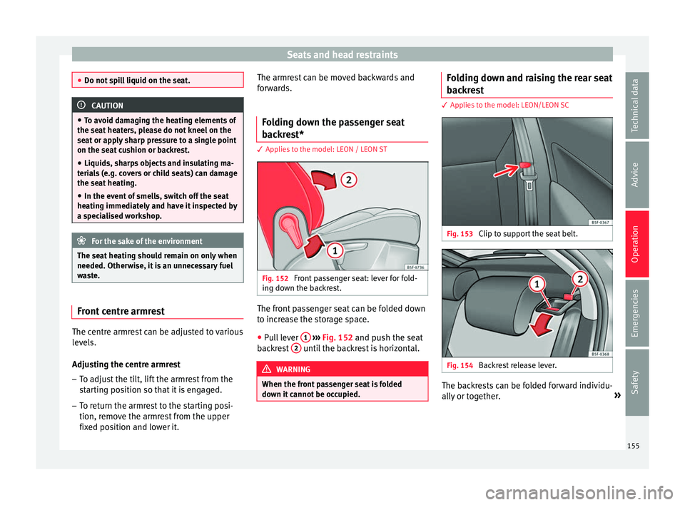
Fig. 152
Front passenger seat: lever for fold-
in g do
wn the b
ackrest. The front passenger seat can be folded down
t
o inc
r
ease the storage space.
● Pull lever 1
› ›
› Fig. 152
and push the seat
backrest 2 until the backrest is horizontal.
WARNING
When the front passenger seat is folded
down it c
annot be occupied. Folding down and raising the rear seat
b
ac
k
rest 3 Applies to the model: LEON/LEON SC
Fig. 153
Clip to support the seat belt. Fig. 154
Backrest release lever. The backrests can be folded forward individu-
al
ly
or t
ogether. »
155
Technical data
Advice
Operation
Emergencies
Safety