turn Seat Leon SC 2017 Owner's Guide
[x] Cancel search | Manufacturer: SEAT, Model Year: 2017, Model line: Leon SC, Model: Seat Leon SC 2017Pages: 332, PDF Size: 7.25 MB
Page 72 of 332

The essentials
Towline anchorages
Att ac
h the b
ar or rope to the towline ancho-
rages.
The towline anchorages are located under
the floor panel in the luggage compartment,
next to the vehicle tools ›››
page 95.
Screw the towline anchorage into the screw
connection ››› Fig. 77 o ››› Fig. 78 and tighten
it with the wheel brace.
Tow rope or tow bar
The tow bar offers increased safety and a
lower risk of damage.
The tow rope is recommended when there is
no tow bar. It must be elastic so that it does
not damage the vehicle.
Notes for the driver of the towing vehicle
● The tow rope must be taut before you drive
off.
● Rel
ease the clutch very carefully when start-
ing the v
ehicle (manual gearbox), or acceler-
ate gently (automatic gearbox).
Driving style
Towing requires some experience, especially
when using a tow rope. Both drivers should
realise how difficult it is to tow a vehicle. In-
experienced drivers should not attempt to
tow. Do not pull too hard with the towing vehicle
and take c
are to avoid jerking the tow rope.
When towing on an unpaved road, there is al-
ways a risk of overloading and damaging the
anchorage points.
Switch on the ignition so that the turn sig-
nals, windscreen wipers and windscreen
washer can work. Ensure that the steering
wheel is unlocked and moves freely.
Place the gear lever in neutral on vehicles
with a manual gearbox. With an automatic
gearbox, place the lever in N.
To brake, press the brake pedal firmly. The
brake servo does not work when the engine
is switched off.
The power steering only works when the igni-
tion is switched on and the vehicle is moving,
provided that the battery is sufficiently charg-
ed. Otherwise, it will need more force.
Ensure that the tow rope remains taut at all
times.
››› in General information on page 98
››› page 98 Tow-starting
If the engine will not start, first try starting it
us
in
g the battery of another vehicle
››› page 70. You should only attempt to tow-
start a vehicle if charging the battery does
not work. This is done by leveraging wheel
movement.
When tow-starting a vehicle with a petrol en-
gine, do not tow it more than a short dis-
tance, otherwise unburned fuel can enter the
catalytic converter.
● Engage 2nd or 3rd gear before moving off.
● Press the clutch and hold the pedal down.
● Switch the ignition on.
● Once both vehicles are moving, release the
clut c
h.
● As soon as the engine has started, press
the clutc
h and move the gear lever to neutral.
How to jump start Jump lea
ds The jump lead must have a sufficient wire
c
r
o
ss section.
If the engine fails to start because of a dis-
charged battery, the battery can be connec-
ted to the battery of another vehicle to start
the engine. 70
Page 73 of 332

The essentials
Jump leads must comply with standard DIN
72553 (see c ab
l
e manufacturer's instruc-
tions). The wire cross section must be at least
25 mm 2
for petrol engines and at least
35 mm 2
for diesel engines. Note
● The v ehic
les must not touch each other,
otherwise electricity could flow as soon as
the positive terminals are connected.
● The discharged battery must be properly
connected t
o the on-board network. How to jump start: description
Fig. 79
Diagram of connections for vehicles
w ithout
Start Stop system Fig. 80
Diagram of connections for vehicles
with St
art Stop system Jump lead terminal connections
Swit
c
h off the ignition of both vehicles
››› .
C onnect
one end of
the red jump lead to
the positive + terminal of the vehicle
w ith the fl
at
battery A
› ›
› Fig. 79 .
Connect the other end of the red jump
lead to the positive terminal + in the
v ehic
l
e providing assistance B .
F or
vehicles without Start-Stop system:
connect one end of the black jump lead
to the negative terminal – of the vehi-
c l
e pr
oviding the current B
› ›
› Fig. 79 .
For vehicles with Start-Stop system: con-
nect one end of the black jump lead X to a suitable ground terminal, to a solid
piec
e of
met
al in the engine block, or to
the engine block itself ››› Fig. 80.
1.
2.
3.
4a.
4b. Connect the other end of the
black
jump
lead X to a solid metal component bol-
t ed t
o the en
gine block or to the engine
block itself of the vehicle with the flat
battery. Do not connect it to a point near
the battery A .
P o
s
ition the leads in such a way that
they cannot come into contact with any
moving parts in the engine compart-
ment.
Starting Start the engine of the vehicle with the
boosting battery and let it run at idling
speed.
Start the engine of the vehicle with the
flat battery and wait for 2 or 3 minutes
until the engine is running.
Removing the jump leads Before you remove the jump leads,
switch off the dipped beam headlights if
they are switched on.
Turn on the heater blower and heated
rear window in the vehicle with the flat
battery. This helps minimise voltage
peaks which are generated when the
leads are disconnected.
When the engine is running, disconnect
the leads in reverse order to the details
given above. »
5.
6.
7.
8.
9.
10.
11.
71
Page 74 of 332

The essentials
Make sure the battery clamps have sufficient
met al-t
o-met
al contact with the battery termi-
nals.
If the engine fails to start after about 10 sec-
onds, switch off the starter and try again after
about 1 minute. WARNING
● Ple a
se note the safety warnings referring to
working in the engine compartment
››› page 270.
● The battery providing assistance must have
the same v
oltage as the flat battery (12V) and
approximately the same capacity (see imprint
on battery). Failure to comply could result in
an explosion.
● Never use jump leads when one of the bat-
teries
is frozen. Danger of explosion! Even af-
ter the battery has thawed, battery acid could
leak and cause chemical burns. If a battery
freezes, it should be replaced.
● Keep sparks, flames and lighted cigarettes
awa
y from batteries, danger of explosion.
Failure to comply could result in an explo-
sion.
● Observe the instructions provided by the
manufact
urer of the jump leads.
● Do not connect the negative cable from the
other vehic
le directly to the negative terminal
of the flat battery. The gas emitted from the
battery could be ignited by sparks. Danger of
explosion. ●
Never att ac
h the negative cable to fuel sys-
tem components or the brake lines in the oth-
er vehicle.
● The non-insulated parts of the battery
clamp
s must not be allowed to touch. The
jump lead attached to the positive battery
terminal must not touch metal parts of the ve-
hicle, this can cause a short circuit.
● Position the leads in such a way that they
cannot c
ome into contact with any moving
parts in the engine compartment.
● Do not lean on the batteries. This could re-
sult
in chemical burns. Note
The vehicles must not touch each other, oth-
erw i
se electricity could flow as soon as the
positive terminals are connected. Changing the wiper blades
W ind
s
creen wipers service position Fig. 81
Wipers in service position. The wiper arms can be raised when the wip-
er
s
ar
e in service position ››› Fig. 81.
● Close the bonnet ›››
page 270.
● Switch the ignition on and off.
● Press the windscreen wiper lever down-
ward
s briefly 4
› ›
› page 32.
Before driving, always lower the wiper arms.
Using the windscreen wiper lever, the wind-
screen wiper arms return to their initial posi-
tion.
››› page 97 72
Page 75 of 332
The essentials
Changing the windscreen and rear
w indo
w w
iper bladesFig. 82
Changing the windscreen wiper
b l
a
des Fig. 83
Changing the rear wiper blade Raising and lowering windscreen wiper arms
● Place the windscreen wipers in the service
po s
ition ›
›› page 72.
● Grip the wiper arms only b
y the blade's fas-
tening point. Cleaning windscreen wiper blades
●
Raise the wiper arms.
● Use a soft cloth to remove dust and dirt
from the wind
screen wiper blades.
● If the blades are very dirty, a sponge or
damp cloth m
ay be used ››› in Changing
the w ind
s
creen and rear window wiper
blades on page 98.
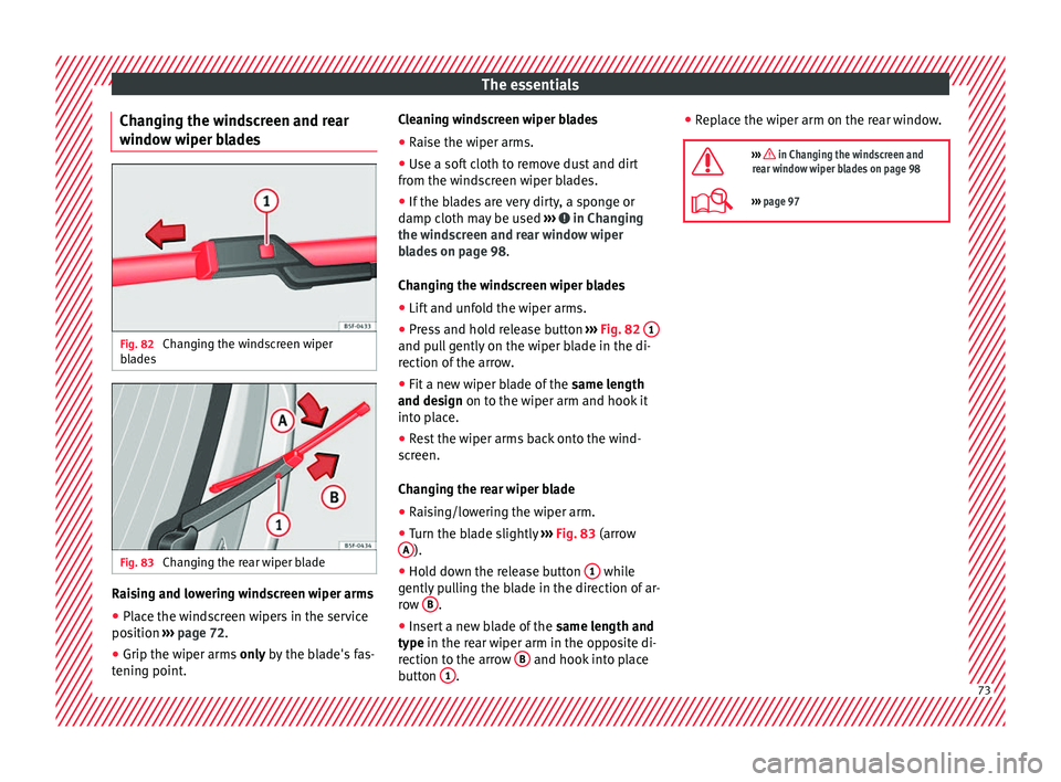
Changing the windscreen wiper blades
● Lift and unfold the wiper arms.
● Press and hold release button ›››
Fig. 82 1 and pull gently on the wiper blade in the di-
r
ection of
the arr
ow.
● Fit a new wiper blade of the same len
gth
and design on to the wiper arm and hook it
into place.
● Rest the wiper arms back onto the wind-
scr
een.
Changing the rear wiper blade
● Raising/lowering the wiper arm.
● Turn the blade slightly ›››
Fig. 83 (arrow
A ).
● Hold down the release button 1 while
g ently
p
ulling the blade in the direction of ar-
row B .
● Insert a new blade of the same l
en
gth and
type in the rear wiper arm in the opposite di-
rection to the arrow B and hook into place
b utt
on 1 .●
Rep
l
ace the wiper arm on the rear window.
››› in Changing the windscreen and
rear window wiper blades on page 98
››› page 97 73
Page 76 of 332
Safety
Safety
Saf e driv
in
g
Safety first! WARNING
● This m
anual contains important informa-
tion about the operation of the vehicle, both
for the driver and the passengers. The other
sections of the on-board documentation also
contain further information that you should
be aware of for your own safety and for the
safety of your passengers.
● Ensure that the on-board documentation is
kept in the
vehicle at all times. This is espe-
cially important when lending or selling the
vehicle to another person. Advice about driving
B ef
or
e setting off For your own safety and the safety of your
p
a
s
sengers, always note the following points
before every trip:
– Make sure that the vehicle's lights and turn
signal
s are working properly.
– Check tyre pressure. –
Ensur
e that all windows provide a clear and
good view of the surroundings.
– Make sure all luggage is secured
›››
page 160.
– Make sure that no objects can interfere
with the pedal
s.
– Adjust front seat, head restraint and mir-
rors
properly according to your size.
– Ensure that the passengers in the rear
seats alw
ays have the head restraints in
the in-use position ››› page 78.
– Instruct passengers to adjust the head re-
straints
according to their height.
– Protect children with appropriate child
seats and pr
operly applied seat belts
››› page 91.
– Assume the correct sitting position. Instruct
your pa
ssengers also to assume a proper
sitting position ››› page 75.
– Fasten your seat belt securely. Instruct your
pas
sengers also to fasten their seat belts
properly ››› page 80.
What affects driving safety? As a driver, you are responsible for yourself
and
y
our p
assengers. When your concentra-
tion or driving safety is affected by any cir- cumstance, you endanger yourself as well as
others on the r
oad ››› , for this reason:
– Always pay attention to traffic and do not
g et
di
stracted by passengers or telephone
calls.
– Never drive when your driving ability is im-
paired (e.
g. by medication, alcohol, drugs).
– Observe traffic laws and speed limits.
– Always reduce your speed as appropriate
for ro
ad, traffic and weather conditions.
– When travelling long distances, take
break
s regularly - at least every two hours.
– If possible, avoid driving when you are tired
or stre
ssed. WARNING
When driving safety is impaired during a trip,
the risk of
injury and accidents increases. Safety equipment
Never put your safety or the safety of your
p
a
s
sengers in danger. In the event of an acci-
dent, the safety equipment may reduce the
risk of injury. The following points cover part
of the safety equipment in your SEAT:
● three-point seat belts,
● belt tension limiters for the front and rear
side seats,
74
Page 81 of 332
Safe driving
Rear head restraints – The rear head restraints have 2 positions:
use
and
non-use.
– One position for use (he
ad restraint raised)
››› Fig. 87. In this position, the head re-
straints are used normally, protecting pas-
sengers along with the rear seat belts.
– And one position for non-use (he
ad re-
straint lowered).
– To fit the head restraints in position for use,
pul
l on the edges with both hands in the
direction of the arrow. WARNING
● Under no cir c
umstances should the rear
passengers travel while the head restraints
are in the non-use position. See the warning
label located on the rear side fixed window
››› Fig. 88.
● Do not swap the centre rear head restraint
with either of the out
er seat rear head re-
straints. Risk of injury in case of an accident! CAUTION
Note the instructions on the adjustment of
the hea d r
estraints ››› page 153. Pedal area
P ed
a
ls –
Ensure that you can always press the accel-
erat or
, brake and clutch pedals unimpaired
to the floor.
– Ensure that the pedals can return unim-
paired t
o their initial positions.
– Ensure that the floor mats are securely fas-
tened during the trip and do not
obstruct
the pedals ››› .
On ly
u
se floor mats which leave the pedals
clear and which are secured to prevent them
from slipping. You can obtain suitable floor
mats from a specialised dealership. Fasten-
ers* for floor mats are fitted in the footwells.
If a brake circuit fails, the brake pedal must
be pressed down thoroughly in order to stop
the vehicle.
Wear suitable footwear
Always wear shoes which support your feet
properly and give you a good feeling for the
pedals. WARNING
● Re s
tricting pedal operation can lead to crit-
ical situations while driving. ●
Never l a
y or fit floor mats or other floor cov-
erings over the original floor mats. This
would reduce the pedal area and could ob-
struct the pedals. Risk of accident.
● Never place objects in the driver footwell.
An obj
ect could move into the pedal area and
impair pedal operation. In the event of a sud-
den driving or braking manoeuvre, you will
not be able to operate the brake, clutch or ac-
celerator pedal. Risk of accident! 79Technical data
Advice
Operation
Emergencies
Safety
Page 86 of 332
Safety
The seat belts are equipped with an automat-
ic r
etr
actor on the shoulder strap. Full free-
dom of movement is permitted when the
shoulder belt is pulled slowly. However, dur-
ing sudden braking, during travel in steep
areas or bends and during acceleration, the
automatic retractor on the shoulder belt is
locked.
The automatic belt retractors on the front
seats are fitted with seat belt tensioners
››› page 84.
Releasing the seat belt ● Press the red button on the belt buckle
›››
Fig. 93 B. The latch plate is released and
springs out ››› .
● Guide the belt back by hand so that it rolls
up e a
s
ily and the trim is not damaged.
Positioning seat belts
Seat belts offer their maximum protection on-
ly when they are properly positioned. WARNING
● The seat belt
s offer best protection only
when the backrests are in an upright position
and the seat belts have been fastened prop-
erly.
● Never put the latch plate in the buckle of
another seat. If
you do this, the seat belt will
not protect you properly and the risk of injury
is increased. ●
Never u nb
uckle a seat belt while the vehi-
cle is in motion. If you do, you increase the
risk of sustaining severe or fatal injuries.
● An incorrectly worn seat belt can cause se-
vere injurie
s in the event of an accident.
● For pregnant women, the lap part of the
seat belt
must lie as low as possible over the
pelvis, never across the stomach, and always
lie flat so that no pressure is exerted on the
abdomen ››› Fig. 94.
● Always engage the retractor lock when you
are securin
g a child seat in group 0, 0+ or 1
››› page 91.
● Read and observe the warnings ›››
page 81. Seat belt tensioners
Ho w the se
at
belt tensioner works Read the additional information carefully
› ›
›
page 21.
The seat belts for the occupants in the front
seats are equipped with belt tensioners. Sen-
sors will trigger the belt tensioners only dur-
ing severe head-on, lateral and rear-end colli-
sions and only if the seat belt is worn. This
retracts and tightens the seat belts, reducing
the forward motion of the occupants.
The belt tensioners will not be triggered in
the event of minor collisions, if the vehicle overturns, or in accidents where no major
forc
es act on the vehicle. Note
● If the se at
belt tensioners are triggered, a
fine dust is produced. This is normal and it is
not an indication of fire in the vehicle.
● The relevant safety requirements must be
obser
ved when the vehicle or components of
the system are scrapped. Specialised work-
shops are familiar with these regulations,
which are also available to you. Maintenance and disposal of belt ten-
s
ioner
s The belt tensioners are components of the
se
at
belts
that are installed in the seats of
your vehicle. If you work on the belt tension-
ers or remove and install parts of the system
when performing other repair work, the seat
belt may be damaged. The consequence may
be that, in the event of an accident, the belt
tensioners function incorrectly or may not
function at all.
So that the effectiveness of the seat belt ten-
sioner is not reduced and that removed parts
do not cause any injuries or environmental
pollution, regulations, which are known to
the specialised workshops, must be ob-
served.
84
Page 88 of 332

Safety
travel on the rear seat. Never transport
chi
l
dren in the vehicle if they are not restrain-
ed or the restraint system is not appropriate
for their age, size or weight.
● If you are not wearing a seat belt, or if you
lean f
orward or to the side while travelling or
assume an incorrect sitting position, there is
a substantially increased risk of injury. This
increased risk of injury will be further in-
creased if you are struck by an inflating air-
bag.
● To reduce the risk of injury from an inflating
airbag, alw
ays wear the seat belt properly
››› page 80.
● Always adjust the front seats properly. Description of airbag system
Read the additional information carefully
› ›
›
page 22.
The airbag system is not a substitute for the
seat belts. The airbag system offers addition-
al protection for the driver and passenger in
combination with the seat belts.
The airbag system comprises the following
modules (as per vehicle equipment): ● Electronic control unit
● Front airbags for driver and passenger
● Knee airbag for the driver
● Side airbags ●
Head airb
ag
● Airbag control lamp on the instrument
p
anel ››› page 90
● Key-operated switch for front passenger air-
bag
● Contr
ol lamp to disconnect/connect the
front airb
ag.
The airbag system operation is monitored
electronically. The airbag control lamp will il-
luminate for a few seconds every time the ig-
nition is switched on (self-diagnosis).
There is a fault in the system if the control
lamp :
● does not light up when the ignition is
switc
hed on ››› page 90,
● turns off after 4 seconds after the ignition
is sw
itched on,
● turns off and then lights up again after the
ignition is sw
itched on,
● illuminates or flashes while the vehicle is
movin
g.
The airbag system is not triggered if:
● the ignition is switched off
● there is a minor frontal collision
● there is a minor side collision
● there is a rear-end collision
● the vehicle turns over. WARNING
● The seat belt
s and airbags can only provide
maximum protection if the occupants are
seated correctly ››› page 75, Correct position
of the vehicle occupants .
● If a fault has occurred in the airbag system,
have the sy
stem checked immediately by a
specialised workshop. Otherwise there is a
danger that during a collision, the system
may fail to trigger, or not trigger correctly. Airbag activation
The airbags deploy extremely rapidly, within
thou
s
andths
of a second, to provide addi-
tional protection in the event of an accident.
A fine dust may develop when the airbag de-
ploys. This is normal and it is not an indica-
tion of fire in the vehicle.
The airbag system is only ready to function
when the ignition is on.
In special accidents instances, several air-
bags may activate at the same time.
In the event of minor head-on and side colli-
sions, rear-end collisions, overturning or roll-
over of the vehicle, airbags do not activate.
Activation factors
The conditions that lead to the airbag system
activating in each situation cannot be gener-
alised. Some factors play an important role,
86
Page 91 of 332
Airbag system
●
The side and he a
d airbags are managed
through sensors located in the interior of the
front doors. To ensure the correct operation of
the side and curtain airbags neither the
doors nor the door panels should be modified
in any way (e.g. fitting loudspeakers). If the
front door is damaged, the airbag system
may not work correctly. All work carried out
on the front door must be done in a special-
ised workshop. Deactivating airbags
A ctiv
ation and de
activation of front
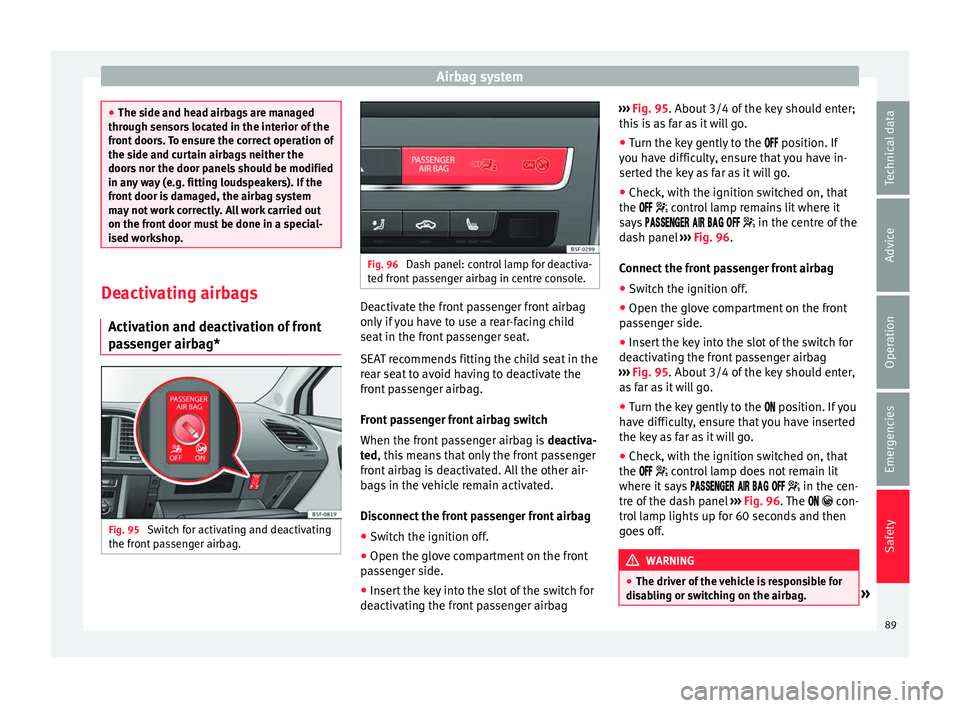
passenger airbag* Fig. 95
Switch for activating and deactivating
the fr ont
p
assenger airbag. Fig. 96
Dash panel: control lamp for deactiva-
ted fr ont
passenger airbag in centre console. Deactivate the front passenger front airbag
on
ly
if
you have to use a rear-facing child
seat in the front passenger seat.
SEAT recommends fitting the child seat in the
rear seat to avoid having to deactivate the
front passenger airbag.
Front passenger front airbag switch
When the front passenger airbag is deactiva-
ted, this means that only the front passenger
front airbag is deactivated. All the other air-
bags in the vehicle remain activated.
Disconnect the front passenger front airbag
● Switch the ignition off.
● Open the glove compartment on the front
pas
senger side.
● Insert the key into the slot of the switch for
deactivatin
g the front passenger airbag ›››
Fig. 95. About 3/4 of the k
ey should enter;
this is as far as it will go.
● Turn the key gently to the position. If
y
ou have difficulty, ensure that you have in-
serted the key as far as it will go.
● Check, with the ignition switched on, that
the contro
l lamp remains lit where it
says in the centre of the
dash panel ››› Fig. 96.
Connect the front passenger front airbag ● Switch the ignition off.
● Open the glove compartment on the front
pas
senger side.
● Insert the key into the slot of the switch for
deactivatin
g the front passenger airbag
››› Fig. 95. About 3/4 of the key should enter,
as far as it will go.
● Turn the key gently to the position. If
you
have difficulty, ensure that you have inserted
the key as far as it will go.
● Check, with the ignition switched on, that
the contro
l lamp does not remain lit
where it says in the cen-
tre of the dash panel ››› Fig. 96. The con-
trol lamp lights up for 60 seconds and then
goes off. WARNING
● The driver of the
vehicle is responsible for
disabling or switching on the airbag. » 89
Technical data
Advice
Operation
Emergencies
Safety
Page 97 of 332
Self-help
Emergencies
Self -help
V ehic
le tool kit, anti-puncture kit* The tools and anti-puncture kit* are stored
under the floor p
anel
in the luggage compart-
ment.
To access the vehicle tools:
– Lift up the floor surface by the plastic han-
dle u nti
l it is fastened to the tabs on both
sides.
Depending on the vehicle equipment, the an-
ti-puncture kit* is located under the floor
panel in the luggage compartment.
The tool kit includes:
● Jack*
● Wire hook for pulling off the wheel cov-
er*/wheel bolt
cap clip.
● Box spanner for wheel bolts*
● Towline anchorage
● Adapter for the anti-theft wheel bolts*
● Towing bracket device
Some of the items
listed are only provided in
certain model versions, or are optional ex-
tras. Note
The jack does not generally require any main-
ten anc
e. If required, it should be greased us-
ing universal type grease. Tyre repair
TMS (T
yre Mobility System)* Read the additional information carefully
›› ›
page 65
The Anti-puncture kit* (Tyre Mobility System)
will reliably seal punctures caused by the
penetration of a foreign body of up to about
4 mm in diameter. Do not remove foreign ob-
jects, e.g. screws or nails, from the tyre.
After inserting the sealant residue in the tyre,
you must again check the tyre pressure about
10 minutes after starting the engine.
You should only use the tyre mobility set if
the vehicle is parked in a safe place, you are
familiar with the procedure and you have the
necessary tyre mobility set! Otherwise, you
should seek professional assistance.
Do not use the tyre sealant in the following
cases:
● If the wheel rim has been damaged.
● In outside temperatures below -20°C (-4°F). ●
In the ev ent
of
cuts or perforations in the
tyre greater than 4 mm.
● If you have been driving with very low pres-
sure or a c
ompletely flat tyre.
● If the sealant bottle has passed its use by
date. WARNING
Using the tyre mobility system can be dan-
ger ou
s, especially when filling the tyre at the
roadside. Please observe the following rules
to minimise the risk of injury:
● Stop the vehicle safely as soon as possible.
Park it
at a safe distance from surrounding
traffic to fill the tyre.
● Ensure the ground on which you park is flat
and solid.
● Al
l passengers and particularly children
must
keep a safe distance from the work area.
● Turn on the hazard warning lights to warn
other roa
d users.
● Use the tyre mobility system only if you are
famili
ar with the necessary procedures. Oth-
erwise, you should seek professional assis-
tance.
● The tyre mobility set is intended for tempo-
rary
emergency use only until you can reach
the nearest specialised workshop.
● Replace the repaired tyre with the tyre mo-
bility
set as soon as possible. » 95
Technical data
Advice
Operation
Emergencies
Safety