turn Seat Leon SC 2017 Service Manual
[x] Cancel search | Manufacturer: SEAT, Model Year: 2017, Model line: Leon SC, Model: Seat Leon SC 2017Pages: 332, PDF Size: 7.25 MB
Page 100 of 332
Emergencies
they should be changed if they are damaged,
or c l
e
aned if they are dirty ››› .
Dam ag
ed w
iper blades should be replaced
immediately. These are available from quali-
fied workshops. WARNING
Worn or dirty windscreen wiper blades reduce
vi s
ibility and increase the risk of accident
and serious injury.
● Always replace damaged or worn wind-
scr
een wiper blades or blades that no longer
clean the windscreen properly. CAUTION
● Damag ed or dir
ty windscreen wipers could
scratch the glass.
● If products containing solvents, rough
spong
es or sharp objects are used to clean
the blades, the graphite layer will be dam-
aged.
● Never use fuel, nail varnish remover, paint
thinner or simil
ar products to clean the win-
dows.
● In icy conditions, always check that the
wiper bl
ades are not frozen to the glass be-
fore using the wipers. In cold weather, it may
help to leave the vehicle parked with the wip-
ers in service position ›››
page 72. CAUTION
● To pr ev
ent damage to the bonnet and the
wiper arms, only leave them in the service
position.
● Before driving, always lower the wiper
arms. Towing or tow-starting
Genera l
information Read the additional information carefully
› ›
›
page 69.
Tow-starting means starting the engine of
the vehicle while another pulls it.
Towing means one vehicle pulling another
that is not roadworthy.
If the vehicle comes with the Keyless Access
system, towing is only allowed with the igni-
tion on!
The vehicle battery drains if the vehicle is
towed with the engine switched off and the
ignition connected. Depending on the battery
charge status, the drop in voltage may be so
large, even after just a few minutes, that no
electrical device in the vehicle may work e.g.
the hazard warning lights. In vehicles with
the Keyless Access system, the steering
wheel could lock up. WARNING
If the vehicle has no electrical power, the
brak e light
s, turn signals and all other lights
will no longer function. Do not have the vehi-
cle towed away. Failure to follow this instruc-
tion could result in an accident. WARNING
The risk of accidents is high when tow-start-
ing, f or e
xample, the towed vehicle can easily
be driven into the towing vehicle. CAUTION
If there is no oil in the gearbox or no lubricant
in the autom atic
transmission the car may
only be towed with the driven wheels lifted
clear of the road, or transported on a special
car transporter or trailer. CAUTION
Do not tow a vehicle for more than 50 m in at-
tempt t
o start it. There is risk of damage to
the catalytic converter. Note
● Ple a
se observe related legal requirements.
● Switch on the hazard warning lights of both
vehicl
es. However, observe any regulations
to the contrary. 98
Page 103 of 332
Fuses and bulbs
is not running, the gearbox oil pump does
not w
ork
and the gearbox is not adequately
lubricated for higher speeds or longer distan-
ces.
If the vehicle has to be towed with a break-
down truck, it must only be suspended at the
front wheels. Reason: the drive shafts are lo-
cated on the front wheels. If the car is towed
with the rear wheels lifted off the road (I.e.
travelling backwards), the drive shafts also
turn backwards. The planetary gears in the
automatic gearbox then turn at such high
speeds that the gearbox will be severely
damaged in a short time. Note
● If it i
s not possible to tow the vehicle in the
normal way, or if it has to be towed further
than 50 km (30 miles), it must be transported
on a special car transporter or trailer.
● Should the power supply to the selector
lever be int
errupted in position P, the selector
lever will be locked. Before the vehicle can be
recovered/manoeuvred you must manually
release the selector lever ›››
page 50. Fuses and bulbs
F u
se
s
Introduction In general, a fuse can be assigned to various
electric
al
components. Likewise, an electrical
component can be protected by several
fuses.
Only replace fuses when the cause of the
problem has been solved. If a newly inserted
fuse blows after a short time, you must have
the electrical system checked by a special-
ised workshop as soon as possible. WARNING
The high voltages in the electrical system can
give seriou s
electrical shocks, causing burns
and even death!
● Never touch the electrical wiring of the igni-
tion syst
em.
● Take care not to cause short circuits in the
electrica
l system. WARNING
Using unsuitable fuses, repairing fuses or
bridging a c urr
ent circuit without fuses can
cause a fire and serious injury. ●
Never u se a f
use with a higher value. Only
replace fuses with a fuse of the same amper-
age (same colour and markings) and size.
● Never repair a fuse.
● Never replace a fuse by a metal strip, staple
or simil
ar. CAUTION
● To pr ev
ent damage to the vehicle's electric
system, before replacing a fuse always turn
off the ignition, the lights and all electrical
elements and remove the key from the igni-
tion.
● If you replace a fuse with higher-rating
fuse,
you could cause damage to another part
of the electrical system.
● Protect the fuse boxes when open to pre-
vent the entr
y of dust or humidity as they can
damage the electrical system. Note
● One component m
ay have more than one
fuse.
● Several components may run on a single
fuse. 101
Technical data
Advice
Operation
Emergencies
Safety
Page 106 of 332
Emergencies
If you choose to change the engine compart-
ment l
amp
s yourself, remember that it is a
dangerous area ››› in Working in the en-
gine c omp
ar
tment on page 270.
Always use identical bulbs with the same
designation. The name can be found on the
base of the bulb holder.
Depending on how equipped the vehicle is,
there are different sets of headlights and tail
lights:
● Halogen headlights.
● Full-LED main headlights*
● Halogen headlights with LED daytime run-
ning lights*
● Re
ar bulb light
● LED rear light*
Ful
l-LED headlight system*
Full-LED headlights handle all light functions
(daylight, side light, turn signal, dipped
beam and route light) with light emitting di-
odes (LEDs) as a light source.
Full-LED headlights are designed to last the
lifetime of the car and light bulbs cannot be
replaced. In case of headlight failure, go to
an authorised workshop to have it replaced. WARNING
● Tak e p
articular care when working on com-
ponents in the engine compartment if the en-
gine is warm. Risk of burns.
● Bulbs are highly sensitive to pressure. The
glas
s can break when you touch the bulb,
causing injury.
● When changing bulbs, please take care not
to injure
yourself on sharp edges, in particu-
lar on the headlight housing. CAUTION
● Remo v
e the ignition key before working on
the electric system. Otherwise, a short circuit
could occur.
● Switch off the lights and the parking light
before c
hanging a bulb.
● Take good care to avoid damaging any com-
ponents. For the sake of the environment
Please ask your specialist retailer how to dis-
pose of u
sed bulbs in the proper manner. Note
● Ple a
se check at regular intervals that all
lighting (especially the exterior lighting) on
your vehicle is functioning properly. This is
not only in the interest of your own safety,
but also that of all other road users. ●
Bef or
e changing a bulb, make sure you
have the correct new bulb.
● Do not touch the glass part of the bulb with
your bar
e hands, use a cloth or paper towel
instead, since the fingerprints left on the
glass will vaporise as a result of the heat gen-
erated by the bulb, they will be deposited on
the reflector and will impair its surface.
● Depending on the level of equipment fitted
in the vehic
le, LEDs may be used for part or
all of the interior and/or exterior lighting.
LEDs have an estimated life that exceeds than
that of the car. If an LED light fails, go to an
authorised workshop for its replacement. 104
Page 107 of 332

Fuses and bulbs
Change the front bulbs Dip ped he
a
dlight bulbFig. 103
Dipped beam headlights. Fig. 104
Dipped beam headlights. –
Raise the bonnet.
– Move the loops ››
›
Fig. 103 1 in the direc-
tion of the arr
o
w and remove the cover. –
Remov
e connector ››› Fig. 104 2 from the
b u
l
b.
– Unclip the retainer spring ›››
Fig. 104 3 pressing inwards to the right.
– Extract the bulb and fit the replacement so
th at
the lug on the b
ase fits into the recess
on the reflector.
Day light bulb Fig. 105
Day light bulb. –
Raise the bonnet.
– Turn the bulb holder ››
›
Fig. 105 1 to the
l ef
t
and pull.
– Remove the bulb by pressing on the bulb
holder and t
urning it anti-clockwise at the
same time.
– Installation involves all of the above steps
in rever
se sequence. Turn signal bulb
Fig. 106
Turn signal bulb. Fig. 107
Turn signal bulb. –
Raise the bonnet.
– Move the loop ››
›
Fig. 106 1 in the direc-
tion of the arr
o
w and remove the cover.
– Turn the bulb holder ›››
Fig. 107 2 anti-
c loc
k
wise and pull. »
105
Technical data
Advice
Operation
Emergencies
Safety
Page 108 of 332

Emergencies
– Remo
v
e the bulb by pressing on the bulb
holder and turning it anti-clockwise at the
same time.
– Installation involves all of the above steps
in rever
se sequence.
Main beam headlight bulb Fig. 108
Main beam headlight bulb. Fig. 109
Main beam headlight bulb. –
Rai
se the bonnet
.
– Move the loop ›››
Fig. 108 1 in the direc-
tion of the arr
o
w and remove the cover.
– Slide connector ›››
Fig. 109 2 to the left or
right and p
u
ll.
– Remove the bulb by disconnecting the con-
nector.
– In
stallation involves all of the above steps
in rever
se sequence. Fog light bulb* 3 Valid only for versions with incandescent bulbs
Fig. 110
Fog light: extracting the grille.106
Page 109 of 332

Fuses and bulbs
Fig. 111
Fog light: remove the bulb holder Follow the steps indicated:
Remo
v
e the screw ››› Fig. 110 1 fr
om
the f og light
grille using a screwdriver
and extract the grille.
Remove the 3 screws ››› Fig. 110 2 .
R emo
v
e the metal clip situated on the
upper part of the fog light by pulling
away from the vehicle 3 and e
xtract
the f og light
.
Remove the connector ››› Fig. 111 1 from the bulb.
T
urn the b
u
lb holder 2 anti-clockwise
and p u
l
l.
Remove the bulb by pressing on the
bulb holder and turning it anticlockwise
at the same time.
Installation involves all of the above
steps in reverse sequence.
Check that the bulb works properly.
1.
2.
3.
4.
5.
6.
7.
8. Note
● Due to the difficulty of accessing fog light
bu l
bs, have them replaced at a Technical
Service or specialised workshop.
● LED fog lights should only be replaced by
speci
alised personnel. Changing incandescent rear
light b
u
lbs
Rear lights summary Tail lights on side panel
Turn signalPY21W NA LL
Side light and brake lightP21W LL
Tail lights on the rear lid
Left side
Side lights2x W5W LL
Fog lightsH21 W
Right side
Side lights2x W5W LL
Reverse lightP21W LL The table corresponds to a right-hand traffic
v
ehic
l
e. The position of lights may vary ac-
cording to the country.
107
Technical data
Advice
Operation
Emergencies
Safety
Page 110 of 332
Emergencies
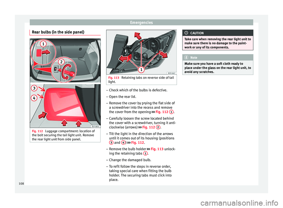
Rear bulbs (in the side panel) Fig. 112
Luggage compartment: location of
the bo lt
sec
uring the tail light unit. Remove
the rear light unit from side panel. Fig. 113
Retaining tabs on reverse side of tail
light. –
Check which of the bulbs is defective.
– Open the rear lid.
– Remove the cover by prying the flat side of
a s c
r
ewdriver into the recess and remove
the cover from the opening ››› Fig. 112 1 .
– Carefully loosen the screw located behind
the c o
v
er with a screwdriver, turning it anti-
clockwise (arrows) ››› Fig. 112 2 .
– Tilt the light in the direction of the arrows
unti
l
it comes out of its housing (positions
3 and
4 )
››
› Fig. 112
.
– Remove the bulb holder ›››
Fig. 113 unlock-
ing the retaining tabs 1 .
– Change the damaged bulb.
– To refit follow the steps in reverse order,
tak
in
g special care when fitting the bulb
holder. The securing tabs must click into
place. CAUTION
Take care when removing the rear light unit to
mak e s
ure there is no damage to the paint-
work or any of its components. Note
Make sure you have a soft cloth ready to
pl ac
e under the glass on the rear light unit, to
avoid any scratches. 108
Page 111 of 332

Fuses and bulbs
Rear light bulbs (in the rear lid) Fig. 114
Remove the cover from the boot lid
and det ac
h the b
ulb holder. Fig. 115
Position of the bulbs in the bulb
hol der The rear lid must be open to change the
b
u
l
bs.
– Remove the rear lid cover in the direction
indicated ›
›› Fig. 114 .
– Unlock the retaining tabs A of the bulb
ho l
der
, following the direction of arrows 1 and
2
› ›
› Fig. 114
.
– Remove the bulb holder, moving it in the
direction of arr
ow 3
› ›
› Fig. 114 .
– Lightly press the defective bulb into the
bul
b holder 1 , then turn it to the left
2 and remove it
››
›
Fig. 115.
– Fit the new bulb, pressing it into the bulb
holder and t
urn it to the right as far as it
will go.
– Use a cloth to remove any fingerprints from
the glas
s part of the bulb.
– Check that the new bulb works properly. –
Reins
tall the bulb holder, making sure that
locking clips A
› ››
Fig. 114
are properly
clipped on.
– Replace the cover of the rear lid lining.
Rear LED light bulb (in the rear lid) Fig. 116
Remove the cover from the rear lid Fig. 117
Remove the bulb holder. » 109
Technical data
Advice
Operation
Emergencies
Safety
Page 112 of 332
Emergencies
The rear lid must be open to change the
b u
l
bs.
– Remove the rear lid cover in the direction
indicated ›
›› Fig. 116.
– Turn the reverse lights bulb holder anti-
clock
wise in the direction of the arrow 1›››
Fig. 117.
– Remove the bulb holder from its housing
2 .
– Change the defective bulb and reinstall the
bu
l
b holder in its housing, following these
instructions in reverse order.
– Check that the new bulb works properly.
Changing number plate light bulbs Fig. 118
In the rear bumper: number plate
light . Fig. 119
Number plate light: Remove the bulb
hol der
. Follow the steps indicated:
1. Press the number plate light in the direc-
tion of the arr
o
w ››› Fig. 118.
2. Remove the number plate light.
3. Turn the connector lock ›››
Fig. 119 in the
direction of arrow 1 and pull on the con-
nect or
.
4.
Rotate the bulb holder in the direction of
arrow 2 and extract it with the bulb.
5. Replace the defective bulb with a new bu
l
b with the same features.
6. Insert the bulb holder in the number plate light and turn in the op
posite direction of
arrow 2 until it stops.
7. Plug the connector into the bulb holder. Note
Depending on how equipped the vehicle is,
the number pl at
e lights may be LEDs. LEDs
have an estimated life that exceeds than that
of the car. If a light with LEDs fails, go to an
authorised workshop for replacement. Side turn signals
Fig. 120
Turn signal integrated in the rear
v iew mirr
or The side turn signals are LEDS and are inte-
gr
at
ed in the e
xterior mirrors.
In case of failure, go to an authorised work-
shop to have them replaced.
110
Page 115 of 332
Controls and displays
Operation
C ontr
o
ls and displays
General instrument panel Door release lever
Centr
al
locking switch . . . . . . . . . . . .128
Electric control to adjust exterior
mirrors . . . . . . . . . . . . . . . . . . . . . . . . . . . 151
Air outl
ets . . . . . . . . . . . . . . . . . . . . . . . . 176
Control lever for:
– Turn s ign
als and main beam
headlights . . . . . . . . . . . . . . . . . . . . . 141
– Lane Ass i
st . . . . . . . . . . . . . . . . . . . . . 224
– Main beam a
ssist . . . . . . . . . . . . . . . 142
– Cruise c
ontrol system (CCS) . . . . .209
Depending on equipment fitted:
– Lev er f
or cruise control . . . . . . . . . .209
Steering wheel with horn and – Driver airbag . . . . . . . . . . . . . . . . . . . 22
– On-boar d c
omputer controls . . . .36
– Contro
ls for radio, telephone,
navigation and speech dialogue
system ›››
Booklet Radio
– Paddle levers for tiptronic gear-
shift (automatic gearbox) . . . . . . .193
Instrument panel . . . . . . . . . . . . . . . . . 114
1 2
3
4
5
6
7
8 Control lever for:
– Wind
s
creen wipers and washer . .148
– Wipe and wa
sh system . . . . . . . . . . 148
– On-board c
omputer . . . . . . . . . . . . . 36
Depending on equipment fitted: ra-
dio or disp
lay for Easy Connect
(navigation, radio, TV/video) . . . . . .120
Depending on the equipment, but-
tons
for:
– SEAT driving modes . . . . . . . . . . . . .230
– Star t
-Stop system . . . . . . . . . . . . . . . 205
– Park a
ssist system . . . . . . . . . . . . . . 237
– Hazard w
arning lights . . . . . . . . . .145
– Tyr
e pressure switch . . . . . . . . . . . .285
– Airbag off di
splay . . . . . . . . . . . . . . . 89
Depending on the equipment,
glov e c
ompartment with: . . . . . . . . .158
– CD pl a
yer* and/or SD card*
››› Booklet Radio
Tyre pressure switch . . . . . . . . . . . . . .285
Front passenger airbag switch . . . .89
Front passenger airbag . . . . . . . . . . .22
Passenger seat heating control . . . .154
Depending on the equipment, con-
tro l
s for:
– Heating and ventilation system or
manual air conditioner . . . . . . . . . .56, 54
– Autom atic
air conditioner . . . . . . .52
9
10
11
12
13
14
15
16
17 Depending on the equipment:
– USB/A UX
-IN inp
ut . . . . . . . . . . . . . . 123
– Connectivity
Box/Wireless Charg-
er* . . . . . . . . . . . . . . . . . . . . . . . . . . . . . 123
– Storag
e compartment
Depending on equipment fitted,
gear lever or selector lever for:
– Manual gearbox . . . . . . . . . . . . . . . . 190
– Automatic
gearbox . . . . . . . . . . . . . 191
Electronic parking brake switch . . .183
Auto Hold switch . . . . . . . . . . . . . . . . . 208
Starter button (Keyless Access lock-
ing and ignition sys
tem) . . . . . . . . . . 180
Driver's seat heating control . . . . . .154
Ignition lock (vehicles without Key-
les
s Access) . . . . . . . . . . . . . . . . . . . . . . 178
Knee airbag . . . . . . . . . . . . . . . . . . . . . . 23
Adjustable steering column . . . . . . .21
Storage compartment
Bonnet lock
release . . . . . . . . . . . . . . . 271
Headlight range control . . . . . . . . . . .146
Headlight switch . . . . . . . . . . . . . . . . . 140
Electric windows . . . . . . . . . . . . . . . . . 136 Note
● Some of the equipment li
sted in this sec-
tion is only fitted on certain models or are op-
tional extras. » 18
19
20
21
22
23
24
25
26
27
28
29
30
31
113
Technical data
Advice
Operation
Emergencies
Safety