SKODA CITIGO 2014 1.G Manual PDF
Manufacturer: SKODA, Model Year: 2014, Model line: CITIGO, Model: SKODA CITIGO 2014 1.GPages: 164, PDF Size: 12.08 MB
Page 71 of 164
CAUTIONMake sure that the luggage compartment cover is correctly engaged in the
side holders B » Fig. 69 - risk of damage to luggage compartment cover/lug-
gage compartment.
Variable loading floor
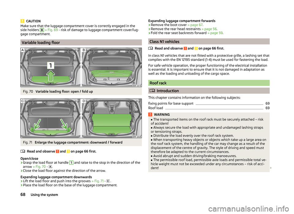
Fig. 70
Variable loading floor: open / fold up
Fig. 71
Enlarge the luggage compartment: downward / forward
Read and observe
and on page 66 first.
Open/close
›
Grasp the load floor at handle
1
and raise to the stop in the direction of the
arrow » Fig. 70 -
.
›
Close the load floor against the direction of the arrow.
Expanding luggage compartment downwards
›
Lift the load floor and push into the grooves » Fig. 71 -
.
›
Place the load floor on the base of the luggage compartment.
Expanding luggage compartment forwards›Remove the boot cover
» page 67.›
Remove the rear head restraints » page 56.
›
Fold the rear seat backrests forward » page 59.
Class N1 vehicles
Read and observe
and on page 66 first.
In class N1 vehicles that are not fitted with a protective grille, a lashing set that
complies with the EN 12195 standard (1-4) must be used for fastening the load.
For safe vehicle operation, the proper functioning of the electrical installation
is essential. It is important to ensure that it is not damaged in adaptation as
well as the loading and unloading of the cargo space.
Roof rack
Introduction
This chapter contains information on the following subjects:
fixing points for base support
69
Roof load
69WARNING■ The transported items on the roof rack must be securely attached – risk
of accident!■
Always secure the load with appropriate and undamaged lashing straps
or tensioning straps.
■
Distribute the load evenly over the roof rack system.
■
When transporting heavy objects or objects which take up a large area on
the roof rack system, the handling of the car may change as a result of the
displacement of the centre of gravity. The style of driving and speed must
therefore be adapted to the current circumstances.
■
Avoid abrupt and sudden driving/braking manoeuvres.
■
The permissible roof load, permissible axle loads and permissible total ve-
hicle weight must not be exceeded under any circumstances – risk of acci-
dent!
68Using the system
Page 72 of 164
CAUTION■Only roof racks from the ŠKODA Original Accessories range should be used.■When dealing with roof racks, the installation instructions supplied with the
roof luggage rack system must be observed.■
On vehicles with a panoramic sunroof, make sure that the tilted panorama
roof does not strike any items which are transported.
■
Ensure that the luggage compartment lid does not hit the roof load when
opened.
■
The height of the vehicle changes after mounting a roof luggage rack system
and the load that is secured to it. Compare the vehicle height with available
clearances, such as underpasses and garage doors.
■
Always remove the roof luggage rack system before entering an automated
car wash.
■
Ensure the roof aerial is not impaired by the secured load.
For the sake of the environment
The increased aerodynamic drag results in a higher fuel consumption.
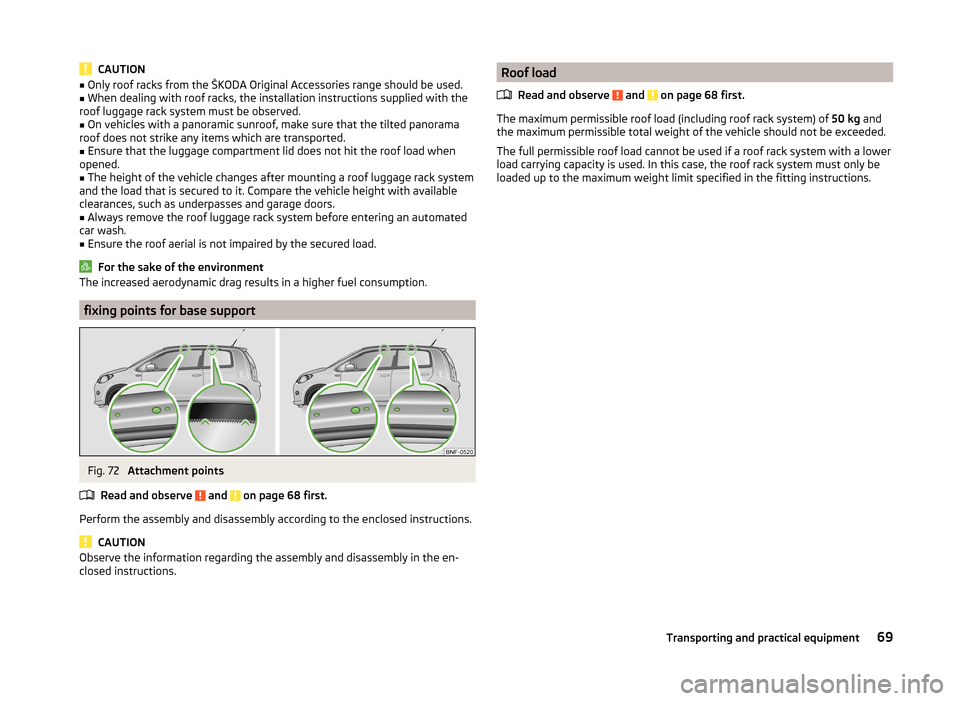
fixing points for base support
Fig. 72
Attachment points
Read and observe
and on page 68 first.
Perform the assembly and disassembly according to the enclosed instructions.
CAUTION
Observe the information regarding the assembly and disassembly in the en-
closed instructions.Roof load
Read and observe
and on page 68 first.
The maximum permissible roof load (including roof rack system) of 50 kg and
the maximum permissible total weight of the vehicle should not be exceeded.
The full permissible roof load cannot be used if a roof rack system with a lower
load carrying capacity is used. In this case, the roof rack system must only be
loaded up to the maximum weight limit specified in the fitting instructions.
69Transporting and practical equipment
Page 73 of 164
Heating and air conditioning
Heating, ventilation, cooling
Introduction
This chapter contains information on the following subjects:
Air outlet vents
71
Controls
71
recirculation
72
Efficient handling of the cooling system
72
malfunctions
72
The heating and air conditioning ventilate and heat the vehicle interior. The air
conditioning system also cools and dehumidifies the vehicle interior.
The heating effect is dependent upon the coolant temperature, thus full heat
output only occurs when the engine has reached its operating temperature.
The cooling system only operates if the following conditions are met. The cooling system is switched on.
The engine is running.
The outside temperature is above approx. +2 °C.
The blower is switched on.
If the cooling system is switched on, the temperature and air humidity drops in
the vehicle. The cooling system prevents the windows from misting up during
winter months.
It is possible to briefly activate recirculated air mode to enhance the cooling
effect » page 72 .
WARNING■
For your own safety and that of other road users, ensure that all the win-
dows are free of ice, snow and misting.■
The blower should always be on to prevent the windows from misting up.
WARNING (Continued)■ Under certain circumstances, air at a temperature of about 5 °C can flow
out of the vents when the cooling system is switched on.■
To reduce health risks (e.g. common colds), the following instructions for
the use of the cooling system are to be observed. ■The difference between the indoor temperature and the outdoor air
temperature should not be greater than about 5 ° C.
■ The cooling system is to be turned off about 10 minutes before the end
of the journey.
■ Once a year, a disinfection of the air conditioner is to be carried out by a
specialist company.
CAUTION
■ The air inlet in front of the windscreen must be free from ice, snow or leaves,
for example, to ensure that the heating and cooling system works properly.■
After switching on the cooling Condensation from the evaporator of the air
conditioning may drip down and form a puddle below the vehicle. This is not a
leak!
■
If the coolant temperature is too high, the cooling system is switched off to
ensure that the engine cools down.
Note
■ The used air streams out through the vents in the luggage compartment.■During operation of the air conditioning, an increase in engine idle speed may
occur under certain circumstances in order to ensure sufficient heating com-
fort.70Using the system
Page 74 of 164
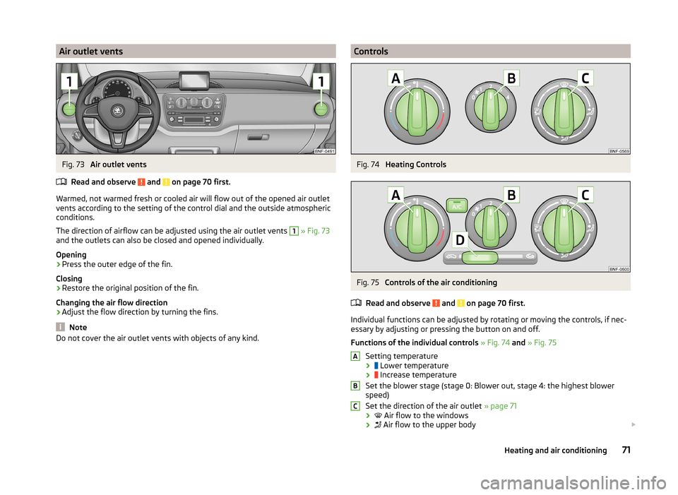
Air outlet ventsFig. 73
Air outlet vents
Read and observe
and on page 70 first.
Warmed, not warmed fresh or cooled air will flow out of the opened air outlet vents according to the setting of the control dial and the outside atmospheric
conditions.
The direction of airflow can be adjusted using the air outlet vents
1
» Fig. 73
and the outlets can also be closed and opened individually.
Opening
›
Press the outer edge of the fin.
Closing
›
Restore the original position of the fin.
Changing the air flow direction
›
Adjust the flow direction by turning the fins.
Note
Do not cover the air outlet vents with objects of any kind.ControlsFig. 74
Heating Controls
Fig. 75
Controls of the air conditioning
Read and observe
and on page 70 first.
Individual functions can be adjusted by rotating or moving the controls, if nec-
essary by adjusting or pressing the button on and off.
Functions of the individual controls » Fig. 74 and » Fig. 75
Setting temperature ›
Lower temperature
›
Increase temperature
Set the blower stage (stage 0: Blower out, stage 4: the highest blower
speed)
Set the direction of the air outlet » page 71
›
Air flow to the windows
›
Air flow to the upper body
ABC71Heating and air conditioning
Page 75 of 164
›
Air flow in the footwell
›
Airflow to the windows and into the footwell
Switch recirculation on/off » page 72
›
Switching recirculated air mode off
›
Switching recirculated air mode on
Switching the cooling system on/off (when this function is switched on,
the warning light illuminates in the button)
Note
The warning light in the button lights after activation, even if not all of the
conditions for the function of the cooling system have been met. By lighting up
of the indicator light in the button, the operational readiness of the cooling
system is signalled.
recirculation
Read and observe
and on page 70 first.
Recirculated air mode mostly prevents polluted air outside the vehicle fromgetting into the vehicle, for example when driving through a tunnel or when
standing in a traffic jam.
In recirculated air mode air is sucked out of the interior of the vehicle and then
fed back into the interior.
The air conditioning system
›
To turn on the air recirculation,. move the slider into position
D
» Fig. 75
on page 71 .
›
To turn off the air recirculation, move the slider into position
D
.
WARNINGThe recirculation system cannot be switched on for a longer period of time,
because there is no supply of fresh air from the outside. “Stale air” may re-
sult in fatigue in the driver and occupants, reduce attention levels and also
cause the windows to mist up. The risk of having an accident increases.
Switch off recirculated air mode as soon as the windows start to mist up.DCAUTIONWe recommend not smoking in the vehicle when the recirculating air operation
is switched on. The smoke sucked from inside the vehicle is deposited on the
evaporator of the air conditioner. This produces a permanent odour when the
air conditioning system is operating which can only be eliminated through con-
siderable effort and expense (replacement of compressor).
Efficient handling of the cooling system
Read and observe
and on page 70 first.
The air conditioning system compressor uses power from the engine when incooling mode, which will affect the fuel consumption.
It recommended to open the windows or the doors of a vehicle for which the
interior has been strongly heated through the effect of direct sunlight in order
to allow the heated air to escape.
The cooling system should not be on if the windows are open.
For the sake of the environment
Pollutant emissions are also reduced when fuel is saved » page 82.
malfunctions
Read and observe
and on page 70 first.
If the cooling system does not operate at outside temperatures higher than +5°C, there is a problem in the system. The reasons for this may be.
› One of the fuses has blown. Check the fuse and replace if necessa-
ry » page 135 .
› The cooling system has switched off automatically for a short time because
the coolant temperature of the engine is too hot » page 33.
If you are not able to resolve the operational problem yourself, or if the cooler
output has reduced, switch off the cooling system and seek assistance from a
specialist garage.
72Using the system
Page 76 of 164
Communication and multimedia
Telephone and Move & Fun
Introduction
This chapter contains information on the following subjects:
Mobile phones and two-way radio systems
73
Multifunction deviceMove & Fun
73
Mobile phones and two-way radio systems
ŠKODA permits the operation of mobile phones and two-way radio systems
with a professionally installed external aerial and a maximum transmission
power of up to 10 watts.
Please consult a ŠKODA Partner for information about the possibility of instal- ling and operating mobile phones and two-way radio systems with a transmis-
sion power of more than 10 W.
Operating mobile phones or two-way radio systems may interfere with the
functionality of the electronic systems in your vehicle.
The possible reasons for this are.
› no external aerial.
› external aerial incorrectly installed.
› transmission power greater than 10 watts.
WARNING■
Concentrate fully at all times on your driving! As the driver you are fully
responsible for the operation of your vehicle. Use the telephone system on-
ly to such an extent that you are in full control of your vehicle at any time.■
The national regulations for using a mobile phone in a vehicle must be
observed.
■
If a mobile phone or a two-way radio system is operated in a vehicle with-
out an external aerial or an external aerial which has been installed incor-
rectly, this can increase the strength of the electromagnetic field inside the
vehicle.
WARNING (Continued)■ Two-way radio systems, mobile phones or mounts must not be installed
on airbag covers or within the immediate deployment range of the airbags.■
Never leave a mobile phone on a seat, on the dash panel or in another
area from which it can be thrown during a sudden braking manoeuvre, an
accident or a collision — risk of injury.
Note
■ We recommend that the installation of mobile phones and two-way radio
systems in a vehicle be carried out by a specialist garage.■
The range of the Bluetooth ®
connection to the hands-free system is restric-
ted to the vehicle interior. The range is dependent on local factors, e.g. obsta-
cles between the devices and mutual interferences with other devices. If your
mobile phone is in a jacket pocket, for example, this can lead to difficulties
when establishing a connection with the hands-free-system or transferring
data.
Multifunction deviceMove & Fun
Fig. 76
Cap of the opening for the cradle
of the multifunction device
Fig. 77
Cradle on the multifunction device/multifunction device
73Communication and multimedia
Page 77 of 164
Removing the cap›Insert a slotted screwdriver into the recess marked with an arrow » Fig. 76
and fold the cover carefully upwards.
Installing the cradle for the navigation unit›
Place the cradle into the opening of the centre section of the dash panel
from above, press it down until it latches » .
Installing the multifunctional device
›
Firstly, place the multifunction device into the top holder
B
» Fig. 77 and
press it on the underside of the cradle until it latches » .
Setting the tilt of the multifunction device
›
You can set the tilt to the required position by moving the multifunction de-
vice in the direction of the arrows » Fig. 77 » .
Removing the multifunction device
›
With one hand, secure the multifunction device on the upper and lower edge.
›
Using the other hand, press the release button
C
» Fig. 77 and remove the
device.
›
Store the multifunction device in a safe place to avoid damaging it.
Removing the cradle on the multifunction device
›
Grab hold of the cradle with one hand.
›
With the other hand, press the release button
A
» Fig. 77 .
›
Remove the cradle from the dash panel from above.
›
Seal the opening for the cradle in the dash panel with the cover » Fig. 76.
Loading the user manual
›
Switch on the multifunction device by pressing button
D
» Fig. 77 .
›
Press the button more on the screen.
›
Press the button Manual on the screen.
›
Call up the required chapter by pressing the appropriate button.
Functions of the multifunction device
› Navigation, TMC traffic information, lane assistance, and speed assistant.
› Operating the radio, media player and multimedia devices connected via
Bluetooth ®
.
› Displaying information from the MFD, rev counter and coolant tempera-
ture » page 28 .
› Hands-free device for mobile phones coupled with the multifunction device
via Bluetooth ®
.
› Indicator for opened bonnet, doors and luggage compartment lid.
› Display from the visual parking system (OPS).
› Image viewer.
›The toll service Live services - traffic, radar to measure the speed on the
road, weather and news search in the Yelpsystem.
› Route planning with consideration of the CNG filling station network (multi-
stop).WARNING■ Concentrate fully at all times on your driving! As the driver you are fully
responsible for the operation of your vehicle. Only use the system such that
you are in full control of your vehicle in every traffic situation – risk of acci-
dent!■
The multifunction device must always slot securely into the cradle or be
safely stored in the vehicle.
■
Unsecured or incorrectly secured multifunction devices may be thrown
through the interior of the vehicle and cause injuries in a sudden driving or
braking manoeuvre or accident.
■
Adjust the volume to ensure that acoustic signals from outside, e.g. sirens
from vehicles which have the right of way, such as police, ambulance and
fire brigade vehicles, can be heard at all time.
■
High volumes can cause hearing damage.
CAUTION
■ Improper tilt settings can damage both the multifunction device and the cra-
dle.■
Always take the multifunction device with you when leaving the vehicle to
protect it from extreme temperatures and strong sunlight. Extreme ambient
temperatures can impair the functioning of the multifunction device and may
damage the device.
■
Moisture can damage the electrical contacts in the dash panel for the porta-
ble multifunction device.
■
Never use water when cleaning the navigation unit cradle. Always use a dry
cloth instead.
■
Install/remove the multifunction device cradle without the multifunction de-
vice in it.
■
Do not install/remove the multifunction device until the cradle for the multi-
function device has been installed into the dash panel.
74Using the system
Page 78 of 164
NoteThe range of the Bluetooth®
connection to the hands-free system is restricted
to the vehicle interior. The range is dependent on local factors, e.g. obstacles
between the devices and mutual interferences with other devices. If your mo-
bile phone is e.g. in a jacket pocket, this can lead to difficulties when establish-
ing the Bluetooth ®
connection with the hands-free system or the data trans-
fer.75Communication and multimedia
Page 79 of 164
Driving
Starting-off and Driving
Starting and turning off the engine
Introduction
This chapter contains information on the following subjects:
Electronic immobilizer
76
Lock/unlock steering lock
76
Ignition on / off and start the engine
77
Switch off engine
77
With the key in the ignition, the ignition can be switched on and off and the
engine can be started / stopped.
WARNING■ While driving with the engine stopped, the ignition must always be
switched on » page 77, Ignition on / off and start the engine .
■ With the ignition off, the steering may lock » page 76 - danger of an
accident!■
Do not withdraw the ignition key from the ignition lock until the vehicle
has come to a stop » page 79, Parking . Otherwise, the steering could be
blocked – risk of accident!
■
Never leave the key in the vehicle when you exit the vehicle. Unauthor-
ized persons, such as children, for example, could lock the car, turn on the
ignition or start the engine - there is a danger of injury, accidents and dam-
age!
■
Never leave the vehicle unattended with the engine running - there is
risk of accident, damage or theft!
■
Never switch off the engine before the vehicle is stationary – risk of acci-
dent!
WARNING■ Never (e.g. in garages) run the engine in a closed place - there is the dan-
ger of poisoning and death!■
Do not leave any items (e.g. cloths or tools) in the engine compartment.
This presents a fire hazard and the risk of engine damage.
■
Never cover the engine with additional insulation material (e.g. with a
cover) – risk of fire!
CAUTION
■ Only start the engine when the engine and the vehicle are stationary - there
is a danger of starter and engine damage!■
Do not push-start the engine – risk of damaging the engine and the catalytic
converter. The battery from another vehicle can be used as a jump-start
aid » page 130 .
Note
Do not warm up the engine while the vehicle is stationary. If possible, start
your journey as soon as the engine has started. Through this, the engine rea-
ches its operating temperature faster.
Electronic immobilizer
Read and observe
and on page 76 first.
The electronic immobilizer makes a possible attempted theft or unauthorizeduse of your vehicle more difficult.
An electronic chip is integrated in the head of the key. The immobiliser is deac-
tivated with the aid of this chip when the key is inserted in the ignition lock.
The electronic immobiliser is automatically activated when the ignition key is
withdrawn from the lock.
The engine will not start if a non-authorized ignition key is used.
Lock/unlock steering lock
Read and observe
and on page 76 first.
The steering lock (steering lock) deters any attempted theft of your vehicle.
Locking
›
Withdraw the ignition key.
76Driving
Page 80 of 164
›Turn the steering wheel to the left or right until the steering lock clicks into
place.
Unlocking›
Insert the key into the ignition lock.
›
Switch on the ignition » page 77.
The steering lock is unlocked.
If the ignition switch can not be turned on, then turn the steering wheel back and forth slightly and thereby unlock the steering lock.
Ignition on / off and start the engine
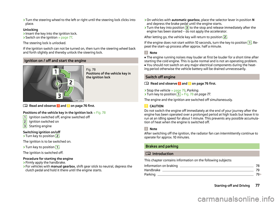
Fig. 78
Positions of the vehicle key in
the ignition lock
Read and observe and on page 76 first.
Positions of the vehicle key in the ignition lock » Fig. 78
Ignition switched off, engine switched off
Ignition switched on
Starting engine
Switching ignition on/off
›
Turn key to position
2
.
The ignition is to be switched on.
›
Turn key to position
1
.
The ignition is switched off.
Procedure for starting the engine
›
Firmly apply the handbrake.
›
For vehicles with manual gearbox, shift gear stick to neutral, depress the
clutch pedal and hold it there until the engine starts.
123› On vehicles with
automatic gearbox , place the selector lever in position N
and depress the brake pedal until the engine starts.›
Turn the key into position
3
to the stop and release immediately after the
engine has been started – do not apply the accelerator.
After letting go, the vehicle key will return to position
2
.
If the engine does not start within 10 seconds, turn the key to position
1
. Re-
peat the start-up process after approx. half a minute.
Note
■ The engine running noises may louder at first be louder for a short time after
starting the cold engine. This is quite normal and is not an operating problem.■
You should not switch on any major electrical components during the heat-
ing period otherwise the vehicle battery will be drained unnecessarily.
Switch off engine
Read and observe
and on page 76 first.
›
Stop the vehicle » page 79, Parking .
›
Turn key to position
1
» Fig. 78 on page 77 .
The engine and the ignition are switched off simultaneously.
CAUTION
Do not switch the engine off immediately at the end of your journey after the
engine has been operated over a prolonged period at high loads but leave it to
run at an idling speed for about 1 minute. This prevents any possible accumula-
tion of heat when the engine is switched off.
Note
After switching off the ignition, the radiator fan can intermittently continue to
operate for approx. 10 minutes.
Brakes and parking
Introduction
This chapter contains information on the following subjects:
Information on braking
78
Handbrake
79
Parking
79
77Starting-off and Driving