battery SKODA FABIA 2014 3.G / NJ Owner's Manual
[x] Cancel search | Manufacturer: SKODA, Model Year: 2014, Model line: FABIA, Model: SKODA FABIA 2014 3.G / NJPages: 216, PDF Size: 30.7 MB
Page 6 of 216
Coolant155Brake fluid156
Vehicle battery
157
Wheels
161
Tyres and rims
161
Manufacturer-approved tyre variants
164
Winter use
165
Do-it-yourself
Emergency equipment, and self-help
167
Emergency equipment
167
Reserve and temporary spare wheel
169
Changing a wheel
170
Breakdown kit
173
Jump-starting
176
Towing the vehicle
177
Remote control
179
Emergency unlocking/locking
180
Replacing windscreen wiper blades
181
Fuses and light bulbs
182
Fuses
182
Replacing bulbs
186
Technical data
Technical data
194
Vehicle data
194
Index
3Table of Contents
Page 10 of 216
AbbreviationsAbbreviationDefinitionrpmEngine revolutions per minuteABSAnti-lock brake systemAGMVehicle battery typeTCSTraction controlCO2Carbon dioxideDSGAutomatic double clutch gearboxEDLElectronic differential lockECEEconomic Commission for EuropeEPCEPC fault lightESCElectronic Stability ControlDRim depthEUEuropean UnionHBAHydraulic brake assistHHCUphill start assistKESSYKeyless unlocking, starting and lockingkWKilowatt, measuring unit for the engine outputMCBMulti-collision brakeMGManual gearboxMPIGasoline engine with a multi-point fuel injectionN1Panel van intended exclusively or mainly for the transporta-
tion of goodsNmNewton meter, measuring unit for the engine torqueTDI CRDiesel engine with turbocharger and common rail injection
systemTSIPetrol engine with turbocharging and direct injectionVINVehicle identification numberWi-Fiwireless data networkXDSFunctional extension of the electronic differential lock7Abbreviations
Page 32 of 216
Depending on equipment fitted:› 12-Volt power socket79
›
Cigarette lighter
78
Depending on equipment fitted:
› Operating controls for the heating
97
›Operating controls for the air conditioning system
98
›Operating controls for Climatronic
98
Note
The layout of the controls on right-hand drive vehicles differs partially from
that shown in » Fig. 19 . The symbols on the controls and switches are the
same as for left-hand drive models.3536Instruments and warning lights
Instrument cluster
Introduction
This chapter contains information on the following subjects:
Overview
30
Revolution counter
30
Display
31
Speedometer
31
Coolant temperature gauge
31
Fuel gauge
32
Counter for distance driven
32
33
Viewing the charge level of the vehicle battery
33
The instrument cluster gives the driver basic information such as the current
speed, engine speed, the state of some vehicle systems and the like.
Fault display
If there is a fault in the instrument cluster, the following message will appear
in the display.
Error: instrument cluster. Workshop!
COMBINED INSTRUM_WORKSHOP
Seek help from a specialist garage.
WARNINGConcentrate fully at all times on your driving! As the driver, you are fully re-
sponsible for road safety.
Note
If the message SAFE CP appears in the instrument cluster display, the compo-
nent protection for the instrument cluster is active. Further information
» page 139 , Component protection .29Instruments and warning lights
Page 33 of 216
OverviewFig. 20
Instrument cluster - Version 1
Fig. 21
Instrument cluster - Version 2
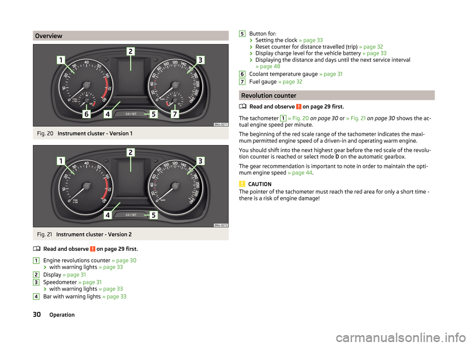
Read and observe
on page 29 first.
Engine revolutions counter » page 30
› with warning lights
» page 33
Display » page 31
Speedometer » page 31
› with warning lights
» page 33
Bar with warning lights » page 33
1234Button for:
› Setting the clock
» page 33
› Reset counter for distance travelled (trip)
» page 32
› Display charge level for the vehicle battery
» page 33
› Displaying the distance and days until the next service interval
» page 48
Coolant temperature gauge » page 31
Fuel gauge » page 32
Revolution counter
Read and observe
on page 29 first.
The tachometer
1
» Fig. 20 on page 30 or » Fig. 21 on page 30 shows the ac-
tual engine speed per minute.
The beginning of the red scale range of the tachometer indicates the maxi-
mum permitted engine speed of a driven-in and operating warm engine.
You should shift into the next highest gear before the red scale of the revolu- tion counter is reached or select mode D on the automatic gearbox.
The gear recommendation is important to note in order to maintain the opti-
mum engine speed » page 44.
CAUTION
The pointer of the tachometer must reach the red area for only a short time -
there is a risk of engine damage!56730Operation
Page 36 of 216

Odometer
The odometer indicates the total distance which the vehicle has been driven.
Read and observe on page 29 first.
›
Switch on the ignition.
›
Press and hold the button
5
» Fig. 20 on page 30 or » Fig. 21 on page 30
until the time is shown.
›
Release the button
5
and the system switches to the time setting function.
›
Press the button
5
again and set the hours.
›
Wait around 4 seconds - the system switches to the minutes setting.
›
Press the button
5
again and set the minutes.
›
Wait around 4 seconds - the system switches to the minutes setting.
The time can also be set in the Infotainment » operating instructions for Info-
tainment , chapter Device settings .
Viewing the charge level of the vehicle battery
Read and observe
on page 29 first.
›
Switch off the ignition.
›
Press and hold the button
5
» Fig. 20 on page 30 or » Fig. 21 on page 30
until Battery status or BATTERY SOC is shown in the Display.
›
Release the button
5
- the current charge level 1)
of the vehicle battery is
displayed in %.
›
Wait about 4 seconds or press the
5
key and the system will return to the
home setting.
Warning lights
Introduction
This chapter contains information on the following subjects:
Handbrake
34
Brake system
34
Seat belt warning light
34
Central warning light
34
Power Steering / steering lock (engine start push-button)34Stability Control (ESC) / Traction Control (ASR)35
Traction control system (TCS) off
35
Anti brake system (ABS)
36
Rear fog light
36
Exhaust inspection system
36
Glow plug system (diesel engine)
36
Engine performance check (petrol engine)
36
Airbag system
36
Tyre pressure
37
Fuel reserve
37
Turning signal system
37
Trailer turn signal lights
37
Fog lights
38
Cruise control / speed limiter
38
Brake pedal (automatic transmission)
38
Main beam
38
The warning lights indicate certain functions or faults.
Some warning lights can be accompanied by acoustic signals and messages in
the display of the instrument cluster.
After switching on the ignition, some warning lights light up briefly as a func-
tion test.
If the tested systems are OK, the corresponding warning lights go out a few
seconds after switching on the ignition or after starting the engine.
The condition of some features and systems is shown by the warning icons on
the display » page 38.
The warning lights are at the following locations in the instrument cluster
» Fig. 20 on page 30 or » Fig. 21 on page 30 .
› Revolutions counter
1
›Speedometer
3
›Bar with warning lights
4
1)
Applies to vehicles with START-STOP system.
33Instruments and warning lights
Page 38 of 216
If the warning light is illuminated , this indicates a partial failure of the Pow-
er Steering and the steering forces can be greater. Seek assistance from a spe-
cialist garage immediately.
Steering lock (engine start push-button)
A long as the warning light
flashes , the steering lock cannot be released.
The following message is shown in the information cluster display. Move the steering wheel!
MOVE STEERING WHEEL
› Move the steering wheel slightly back and forth, thereby facilitating unlock-
ing the steering lock.
If the steering does also not unlock then, the help of a specialist garage is re-
quired.
If the warning light
flashes and a beep sounds, the electric steering lock is
faulty.
The following message is shown in the information cluster display. Steering lock: Workshop!
STEERING WORKSHOP
Seek assistance from a specialist garage immediately.
If the warning light
flashes and a beep sounds, the electric steering lock is
faulty.
The following message is shown in the information cluster display. Steering lock faulty. Stop!
STOP! VEHICLE STEERING FAULTY
Park the vehicle, and
stop driving . After switching off the ignition, it is no
longer possible to lock the steering, to activate the electrical components (e.g.
radio etc), to switch on the ignition again and to start the engine. Seek help
from a specialist garage.
Note
If the vehicle's battery has been disconnected and reconnected, the indicator
light comes on after switching on the ignition. The warning light should go
out after driving a short distance. If, after the motor is restarted and a short
drive, the indicator light
does not go out, there is a system error. Seek assis-
tance from a specialist garage immediately.Stability Control (ESC) / Traction Control (ASR)
Read and observe
on page 34 first.
If the warning light
flashes , the ESC or the ASR is just intervening at that
time.
If the warning light
lights up , there is an error in the ESC or the ASR.
The following message is shown in the information cluster display. Error: Electronic Stability Control (ESC)
ESC ERROR
Error: Traction control
ASR ERROR
Seek assistance from a specialist garage immediately.
If the warning light comes on after starting the engine, the TCS may be
switched off for technical reasons.
›
Switch the ignition off and on again.
If the warning light does not illuminate after you switch the engine back on,
the ASR is fully functional again.
Further information » page 115, Electronic Stability Control (ESC) or
» page 115 , Traction Control System (TCS) .
Note
The warning light comes on after the ignition is switched on if the vehicle's
battery has been disconnected and reconnected. If the indicator light does not
go out after moving a short distance, this means that there is an error in the
system. Seek assistance from a specialist garage immediately.
Traction control system (TCS) off
Read and observe
on page 34 first.
If the warning light
is illuminated , the TCS is switched off.
Activating/deactivating TCS » page 115, Traction Control System (TCS) .
35Instruments and warning lights
Page 40 of 216
Tyre pressureRead and observe
on page 34 first.
The warning light
is illuminated
If the warning light
comes on while driving, it means one of the tyres has
undergone a pressure change.
An audible signal sounds as a warning signal.
›
Immediately reduce speed and avoid sudden steering and braking manoeu-
vres.
›
Stop the vehicle, turn the ignition off and check the tyres and their inflation
pressure » page 162 .
›
Correct the tyre pressure, if necessary or replace the affected wheel
» page 170 or use the repair kit » page 173.
›
Store the tyre pressure values in the system
» page 127.
The indicator light flashes for about 1 min. and remains lit
If the warning light flashes for approximately 1 min. and stays on, there may
be a fault in the system of tyre pressure monitoring.
›
Stop the vehicle, turn the ignition off and start the engine again.
If the warning light flashes again after the engine has started, there is a
system error.
Seek help from a specialist garage.
The following reasons can also apply if the warning light is illuminated.
› The vehicle is loaded on one side. Distribute loads as evenly as possible.
› The wheels of one axle are loaded more heavily (e.g. when towing a trailer or
when driving uphill or downhill).
› Snow chains are fitted.
› A wheel has been changed.
Store the tyre pressure values in the system » page 127.
CAUTION
Under certain circumstances (e.g. sporty style of driving, wintry or unpaved
roads) the warning light in the instrument cluster can be delayed or does
not light up at all.NoteThe warning light comes on after the ignition is switched on if the vehicle's
battery has been disconnected and reconnected. If the indicator light does not
go out after moving a short distance, this means that there is an error in the
system. Seek help from a specialist garage.
Fuel reserve
Read and observe
on page 34 first.
When the warning light
is illuminated , this means there is a fuel reserve of
under around 7 litres left.
The following message is shown in the information cluster display. Please refuel. Range: ... km
PLEASE REFUEL RANGE …
An audible signal sounds as a warning signal.
CAUTION
Never drive until the fuel tank is completely empty! The irregular supply of fuel
can cause misfiring. This can result in considerable damage to parts of the en-
gine and the exhaust system.
Note
The text in the display goes out after refuelling and driving a short distance.
Turning signal system
Read and observe
on page 34 first.
Either the left or the right
warning light
flashes depending on the position
of the turn signal lever.
If there is a fault in the turn signal system, the warning light flashes at twice
its normal rate. This does not apply when towing a trailer.
When the hazard warning light system is switched on, this will cause all of the
turn signal lights as well as both warning lights to flash.
Trailer turn signal lights
Read and observe
on page 34 first.
If the warning light
flashes , the trailer turn signal lights are turned on.
37Instruments and warning lights
Page 42 of 216

If the tested systems are OK, the corresponding warning lights go out for a
few seconds after switching on the ignition or after starting the engine.
The status of some features and systems is shown by the warning lights
» page 33 .WARNING■
Ignoring illuminated warning icons and related messages or instructions
in the display of the instrument cluster may lead to serious personal injury
or damage to the vehicle.■
If you have to stop for technical reasons, then park the vehicle at a safe
distance from the traffic, switch off the engine and activate the hazard
warning lights system » page 64. The warning triangle must be set up at
the prescribed distance - observe the national legal provisions when doing
so.
■
The engine compartment of your car is a hazardous area. While working in
the engine compartment, be sure to observe the following warnings
» page 150 , Engine compartment .
Automatic transmission
Read and observe
on page 39 first.
The warning icon and the corresponding message indicate a malfunction or
the status of the automatic transmission.
The warning icon and the message is shown in the MAXI DOT display.
The message appears only in the segment display.
Message, meaning and action
Gearbox faulty. Workshop!
GEARBOX FAULTY WORKSHOP Fault in the automatic transmission.
Seek assistance from a specialist garage immediately.
Gearbox overheated. Stop! Owner's Manual!
STOP VEHICLE GEARBOX OVERHEAT
Gearbox overheated.
GEARBOX OVERHEATEDMessage, meaning and action
The temperature of the automatic transmission clutches is too high. do not continue to drive!
Stop the vehicle and turn off the engine.
Switch on the ignition and wait until the message disappears – risk of
gearbox damage!
The journey can be continued as soon as the warning light and the mes-
sage go out.
If the warning light and the message do not go out, do not continue
driving. Seek help from a specialist garage.
Error: gearbox. Reverse gear not available.
GEARBOX ERROR REV_ GEAR NOT AVAIL Fault in the automatic transmission, reverse gear cannot be engaged.
Seek assistance from a specialist garage immediately.
Error: Transmission
GEARBOX ERROR Fault in the automatic transmission.
Seek assistance from a specialist garage immediately.
Rear seat belt warning
Read and observe
on page 39 first.
A rear seat belt is not fastened
A rear seat belt is fastened
The warning icons or
light up after the ignition has been switched on.
When the seat belt is fastened/unfastened, the respective icon lights up brief-
ly and indicates the current belt status.
Alternator
Read and observe
on page 39 first.
The warning icon
lights up if the vehicle battery is not charged when the
engine is running.
Seek assistance from a specialist garage immediately.
39Instruments and warning lights
Page 49 of 216
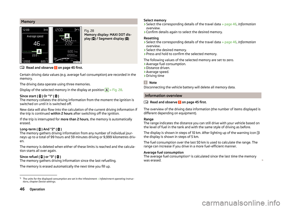
MemoryFig. 28
Memory display: MAXI DOT dis-
play (
) / Segment display (
)
Read and observe on page 45 first.
Certain driving data values (e.g. average fuel consumption) are recorded in the
memory.
The driving data operate using three memories.
Display of the selected memory in the display at position
A
» Fig. 28 .
Since start ( ) Or “1” (
)
The memory collates the driving information from the moment the ignition is
switched on until it is switched off.
New data will also flow into the calculation of the current driving information if
the trip is continued within 2 hours after switching off the ignition.
If the trip is interrupted for more than 2 hours, the memory is automatically
erased.
Long-term ( ) And “2” (
)
The memory gathers driving information from any number of individual jour-
neys up to a total of 99 hours and 59 minutes driving or 9,999 kilometres driv-
en.
The memory is deleted when either of these limits is reached and the calcula-
tion starts all over again.
Since refuel ( ) or “3” (
)
The memory gathers driving information since the last refuelling.
The memory is erased automatically the next time you fill up.
Select memory›Select the corresponding details of the travel data » page 46, Information
overview .›
Confirm details again to select the desired memory.
Resetting
›
Select the corresponding details of the travel data » page 46, Information
overview .
›
Select the desired memory.
›
Press and hold to confirm the selected memory.
The following values of the selected memory are set to zero. › Average fuel consumption.
› Distance driven.
› Average speed.
› Driving time
Note
Disconnecting the vehicle battery will delete all memory data.
Information overview
Read and observe
on page 45 first.
The overview of the driving data information (the number of items displayed is
different depending on equipment).
Range
The range indicates the distance you can still drive with your vehicle based on
the level of fuel in the tank and with the same style of driving as before.
The display is shown in steps of 10 km. After lighting up of the warning icon
the display is shown in steps of 5 km.
The fuel consumption over the last 50 km is used to calculate the range. The
range can increase if you drive in a more fuel-efficient manner.
Average fuel consumption
The average fuel consumption 1)
is calculated since the last time the memory
was erased.
1)
The units for the displayed consumption are set in the Infotainment
» Infotainment operating instruc-
tions , chapter Device settings .
46Operation
Page 51 of 216
›Store the speed limit by confirming the set value, or wait several seconds.
Your settings will be saved automatically.
This allows you to set the speed in 5 km/h intervals.
Adjusting the speed limit while the vehicle is moving›
Select the menu item Warning at (
) or
(
).
›
Drive at the desired speed, e.g. 50 km/h.
›
Confirm the current speed as the speed limit.
If you wish to adjust the set speed limit, you can do so in 5 km/h intervals (e.g.
the accepted speed of 47 km/h increases to 50 km/h or decreases to 45 km/h).
›
+Store the speed limit, or wait several seconds; your settings will be saved
automatically.
Change or disable speed limit
›
Select the menu item Warning at (
) or
(
).
›
By confirming the stored value, the speed limit is disabled.
›
By reconfirming, the option to change the speed limit is activated.
The speed limit set mode is stored even after the ignition is switched off and
on. After a gap between driving exceeding 2 hours, the pre-set speed limit is
deactivated.
Service interval display
Introduction
This chapter contains information on the following subjects:
Displaying the distance and days until the next service interval
48
Service messages
48
Resetting the service interval display
49
The service interval display shows the time and mileage to the next service
event.
The information regarding the service intervals can be found in the service
schedule.
Note
Information is retained in the Service Interval Display even after the vehicle
battery is disconnected.Displaying the distance and days until the next service interval
There is always the option to display the remaining days and miles until the
next service date in the display.›
Switch on the ignition.
›
Press the button
5
» Fig. 20 on page 30 or » Fig. 21 on page 30 and hold
down until the menu item Service appears in the display.
›
Release the button
5
.
The icon
appears in the display, as well as the following message for exam-
ple.
Oil change in … km or Oil change in … days
OIL CHANGE IN ... DAYS or OIL CHANGE IN …
› Press the button
5
and the system switches to the home setting.
Service messages
Messages before reaching the scheduled service date
Before the next service date has been reached, the symbol as well as a mes-
sage about the mileage or days until the next service event appears in the dis-
play after switching on the ignition.
This indicator decreases in steps of 100 km or in days.
Messages upon reaching scheduled service date
Once the service interval is reached, the icon appears in the display after the
ignition is switched on, as well as the following message, for example.
Oil change now!
OIL CHANGE NOW
or Inspection now!
INSPECTION NOW
or Oil change and inspection now!
OIL CHAN_ AND INSPECTION NOW
48Operation