SKODA OCTAVIA 2013 3.G / (5E) Owner's Manual
Manufacturer: SKODA, Model Year: 2013, Model line: OCTAVIA, Model: SKODA OCTAVIA 2013 3.G / (5E)Pages: 287, PDF Size: 18.55 MB
Page 261 of 287
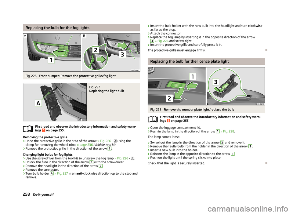
Replacing the bulb for the fog lightsFig. 226
Front bumper: Remove the protective grille/fog light
Fig. 227
Replacing the light bulb
First read and observe the introductory information and safety warn-
ings on page 255.
Removing the protective grille
›
Undo the protective grille in the area of the arrow » Fig. 226 -
using the
clamp for removing the wheel trims » page 236, Vehicle tool kit .
›
Remove the protective grille in the direction of the arrow
1
.
Changing light bulbs for fog lights
›
Use the screwdriver from the tool kit to unscrew the fog lamp » Fig. 226 -
.
›
Unlock the fuse in the direction of the arrow
2
with the screwdriver.
›
Remove the headlight in the direction of the arrow
3
.
›
Remove the connector.
›
Turn bulb holder
A
» Fig. 227 in an anti-clockwise direction up to the stop and
remove.
› Insert the bulb holder with the new bulb into the headlight and turn
clockwise
as far as the stop.›
Attach the connector.
›
Replace the fog lamp by inserting it in the opposite direction of the arrow
3
» Fig. 226 and screw tight.
›
Insert the protective grille and carefully press it in.
The protective grille must engage firmly.
Replacing the bulb for the licence plate light
Fig. 228
Remove the number plate light/replace the bulb
First read and observe the introductory information and safety warn- ings
on page 255.
›
Open the luggage compartment lid.
›
Push in the lamp in the direction of the arrow
1
» Fig. 228 .
The lamp comes loose.
›
Swivel out the lamp in the direction of the arrow
2
and remove it.
›
Remove the faulty bulb from the holder in the direction of the arrow
3
.
›
Insert a new bulb into the holder.
›
Reinsert the lamp in the opposite direction to the arrow
1
.
›
Push on the light until the spring clicks into place.
Check that the light is securely inserted.
258Do-it-yourself
Page 262 of 287
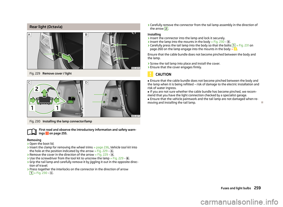
Rear light (Octavia)Fig. 229
Remove cover / light
Fig. 230
Installing the lamp connector/lamp
First read and observe the introductory information and safety warn-
ings
on page 255.
Removing
›
Open the boot lid.
›
Insert the clamp for removing the wheel trims » page 236, Vehicle tool kit into
the hole at the position indicated by the arrow » Fig. 229 -
.
›
Remove the cover in the direction of the arrow » Fig. 229 -
.
›
Use the screwdriver from the tool kit to unscrew the lamp » Fig. 229 -
.
›
Grip the tail lamp and carefully remove it by jiggling it out in the opposite direc-
tion of travel.
›
Press together the interlocks on the connector in the direction of arrow
1
» Fig. 230 -
.
›Carefully remove the connector from the tail lamp assembly in the direction of
the arrow 2.
Installing›
Insert the connector into the lamp and lock it securely.
›
Insert the lamp into the mounts in the body » Fig. 230 - .
›
Carefully press the tail lamp into the body so that the bolts
1
» Fig. 231 on
page 260 on the lamp engage into the mounts in the body » .
Ensure that the cable bundle does not become pinched between the body and
the lamp.
›
Screw the tail lamp into place and install the cover.
›
Ensure that the cover engages firmly.
CAUTION
■ Ensure that the cable bundle does not become pinched between the body and
the lamp when it is being refitted – risk of damage to the electric installation and risk of water ingress.■
If you are not sure whether the cable bundle has become pinched, we recom-
mend that you have the light connection checked by a specialist garage.
■
Ensure that the vehicle paintwork and the tail lamp are not damaged when re-
moving and installing the tail lamp.
259Fuses and light bulbs
Page 263 of 287
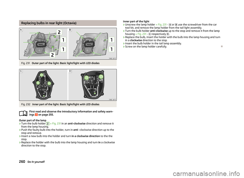
Replacing bulbs in rear light (Octavia)Fig. 231
Outer part of the light: Basic light/light with LED diodes
Fig. 232
Inner part of the light: Basic light/light with LED diodes
First read and observe the introductory information and safety warn-
ings
on page 255.
Outer part of the lamp
›
Turn the bulb holder
2
» Fig. 231 in an anti-clockwise direction and remove it
from the lamp housing.
›
Push the faulty bulb into the holder, turn in anti -clockwise direction up to the
stop and remove.
›
Insert a new bulb into the holder and turn in a clockwise direction to the the
stop.
›
Replace the holder with the bulb into the lamp housing and turn in a clockwise
direction to the stop.
Inner part of the light›Unscrew the lamp holder » Fig. 231 - or use the screwdriver from the car
tool kit, and remove the lamp holder from the tail light assembly.›
Turn the bulb holder anti-clockwise up to the stop and remove it from the lamp
housing » Fig. 231 - respectively .
›
Replace the bulb, insert the holder with the bulb into the lamp housing and turn
in a clockwise direction to the stop.
›
Insert the bulb holder in the tail lamp assembly.
›
Screw on the lamp holder carefully.
260Do-it-yourself
Page 264 of 287
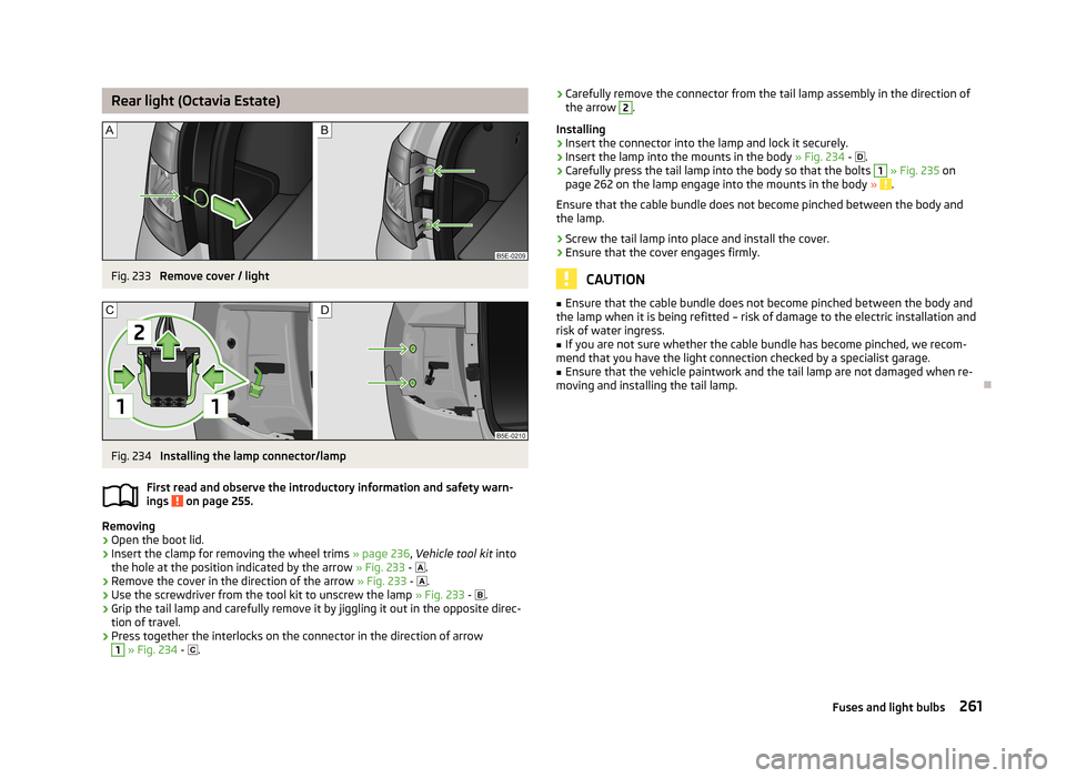
Rear light (Octavia Estate)Fig. 233
Remove cover / light
Fig. 234
Installing the lamp connector/lamp
First read and observe the introductory information and safety warn-
ings
on page 255.
Removing
›
Open the boot lid.
›
Insert the clamp for removing the wheel trims » page 236, Vehicle tool kit into
the hole at the position indicated by the arrow » Fig. 233 -
.
›
Remove the cover in the direction of the arrow » Fig. 233 -
.
›
Use the screwdriver from the tool kit to unscrew the lamp » Fig. 233 -
.
›
Grip the tail lamp and carefully remove it by jiggling it out in the opposite direc-
tion of travel.
›
Press together the interlocks on the connector in the direction of arrow
1
» Fig. 234 -
.
›Carefully remove the connector from the tail lamp assembly in the direction of
the arrow 2.
Installing›
Insert the connector into the lamp and lock it securely.
›
Insert the lamp into the mounts in the body » Fig. 234 - .
›
Carefully press the tail lamp into the body so that the bolts
1
» Fig. 235 on
page 262 on the lamp engage into the mounts in the body » .
Ensure that the cable bundle does not become pinched between the body and
the lamp.
›
Screw the tail lamp into place and install the cover.
›
Ensure that the cover engages firmly.
CAUTION
■ Ensure that the cable bundle does not become pinched between the body and
the lamp when it is being refitted – risk of damage to the electric installation and risk of water ingress.■
If you are not sure whether the cable bundle has become pinched, we recom-
mend that you have the light connection checked by a specialist garage.
■
Ensure that the vehicle paintwork and the tail lamp are not damaged when re-
moving and installing the tail lamp.
261Fuses and light bulbs
Page 265 of 287
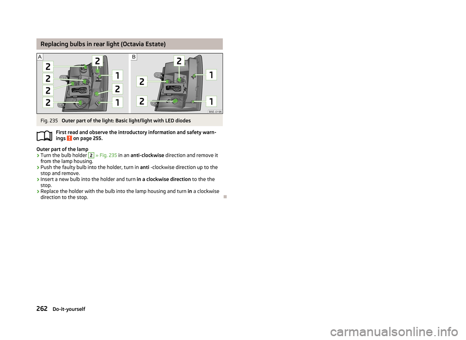
Replacing bulbs in rear light (Octavia Estate)Fig. 235
Outer part of the light: Basic light/light with LED diodes
First read and observe the introductory information and safety warn-
ings
on page 255.
Outer part of the lamp
›
Turn the bulb holder
2
» Fig. 235 in an anti-clockwise direction and remove it
from the lamp housing.
›
Push the faulty bulb into the holder, turn in anti -clockwise direction up to the
stop and remove.
›
Insert a new bulb into the holder and turn in a clockwise direction to the the
stop.
›
Replace the holder with the bulb into the lamp housing and turn in a clockwise
direction to the stop.
262Do-it-yourself
Page 266 of 287
Technical data
Technical data
Vehicle data
Introduction
This chapter contains information on the following subjects:
Vehicle identification data
263
Dimensions
265
Vehicle-specific information depending on engine type
267
The details given in the vehicle's technical documentation always take prece-
dence over the details in the Owner's Manual.
The listed performance values were determined without performance-reducing
equipment, e.g. air conditioning system.
Vehicle identification data
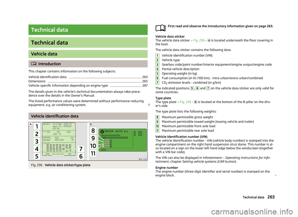
Fig. 236
Vehicle data sticker/type plate
First read and observe the introductory information given on page 263.
Vehicle data sticker
The vehicle data sticker » Fig. 236 - is located underneath the floor covering in
the boot.
The vehicle data sticker contains the following data: Vehicle identification number (VIN)
Vehicle type
Gearbox code/paint number/interior equipment/engine output/engine code Partial vehicle description
Operating weight (in kg) Fuel consumption (in ltr./100 km) - intra-urban/extra-urban/combined
CO 2 emission levels - combined (in g/km)
The indicated positions
5
,
6
and
7
on the vehicle data sticker are only valid for
some countries.
Type plate
The type plate » Fig. 236 -
is located at the bottom of the B-pillar on the driv-
er's side.
The type plate lists the following weights: Maximum permissible gross weight
Maximum permissible towed weight (towing vehicle and trailer)
Maximum permissible front axle load
Maximum permissible rear axle load
Vehicle identification number (VIN)
The vehicle identification number - VIN (vehicle body number) is stamped into the
engine compartment on the right hand suspension strut dome. This number is al- so located on a sign on the lower left hand edge below the windscreen (together
with a VIN bar code).
The VIN can also be displayed in Infotainment » Operating instructions for Info-
tainment , chapter Setting vehicle systems (CAR button) .
Engine number
The engine number (three-digit identifier and serial number) is stamped on the engine block.
1234567891011263Technical data
Page 267 of 287
Operating weight
The specified operating weight is for orientation purposes only. This value repre- sents the minimum operating weight without additional weight-increasing equip-ment such as air conditioning system, spare wheel, or trailer hitch.
The operating weight also contains the weight of the driver (75 kg), the weight of
the operating fluids, the tool kit, and a fuel tank filled to 90 % capacity.
It is possible to calculate the approximate loading capacity from the difference
between the permissible total weight and the operating weight »
.
The payload consists of the following components: › Passengers
› All items of luggage and other loads
› Roof load including roof rack system
› Equipment not included in the operating weight
› Trailer hook weight when towing (up to 75 kg and 80 kg for the Octavia Combi
4x4 vehicles).
Fuel consumption and CO 2 emissions according to ECE regulations and EU
directives
The measurement of the intra-urban cycle begins with a cold start of the engine. Afterwards standard urban driving is simulated.
In the extra-urban driving cycle, the vehicle is accelerated and decelerated in all
gears, corresponding to daily routine driving conditions. The driving speed varies
between 0 and -120 km/h.
The calculation of the combined fuel consumption considers a weighting of about 37 % for the intra-urban cycle and 63 % for the extra-urban cycle.
WARNINGDo not exceed the specified maximum permissible weights – risk of accident
and damage!Note■ If required, you can find out the precise weight of your vehicle at a specialist ga-
rage.■
The fuel consumption and emission values have been determined in accordance
with rules and under conditions set out by legal or technical requirements for de-
termining operational and technical data for motor vehicles.
■
Depending on the range of equipment, style of driving, traffic situation, weather
influences and vehicle condition, consumption values may deviate from the indi-
cated values.
264Technical data
Page 268 of 287
DimensionsFirst read and observe the introductory information given on page 263.
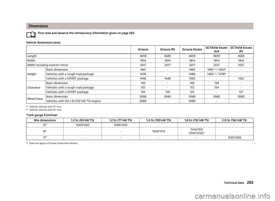
Vehicle dimensions (mm)
OctaviaOctavia RSOctavia EstateOCTAVIA Estate4x4OCTAVIA Estate RSLength46594685465946594685Width18141814181418141814Width including exterior mirror20172017201720172017
Height
Basic dimension.1461-14651465 a)
/ 1463 b)-Vehicles with a rough road package.1476-14801480 a)
/ 1478 b)-Vehicles with a SPORT package.144614491450-1452
Clearance
Basic dimension.140-140139-Vehicles with a rough road package.155-155154-Vehicles with a SPORT package.125128125-127Wheel baseBasic dimension.26862680268626802680Vehicles with the 1.8 l/132 kW TSI engine.2680-2680--a)
Valid for vehicles with 15" rims.
b)
Valid for vehicles with 16" rims.
Track gauge front/rear
Rim dimensions1.2 ltr./63 kW TSI1.2 ltr./77 kW TSI1.4 ltr./103 kW TSI1.8 ltr./132 kW TSI2.0 ltr./162 kW TSI15"1549/15201549/1520---16"--1543/15141543/1512
(1541/1510) a)-17"----1535/1506a)
Does not apply to Octavia Estate 4x4 vehicles.
265Technical data
Page 269 of 287
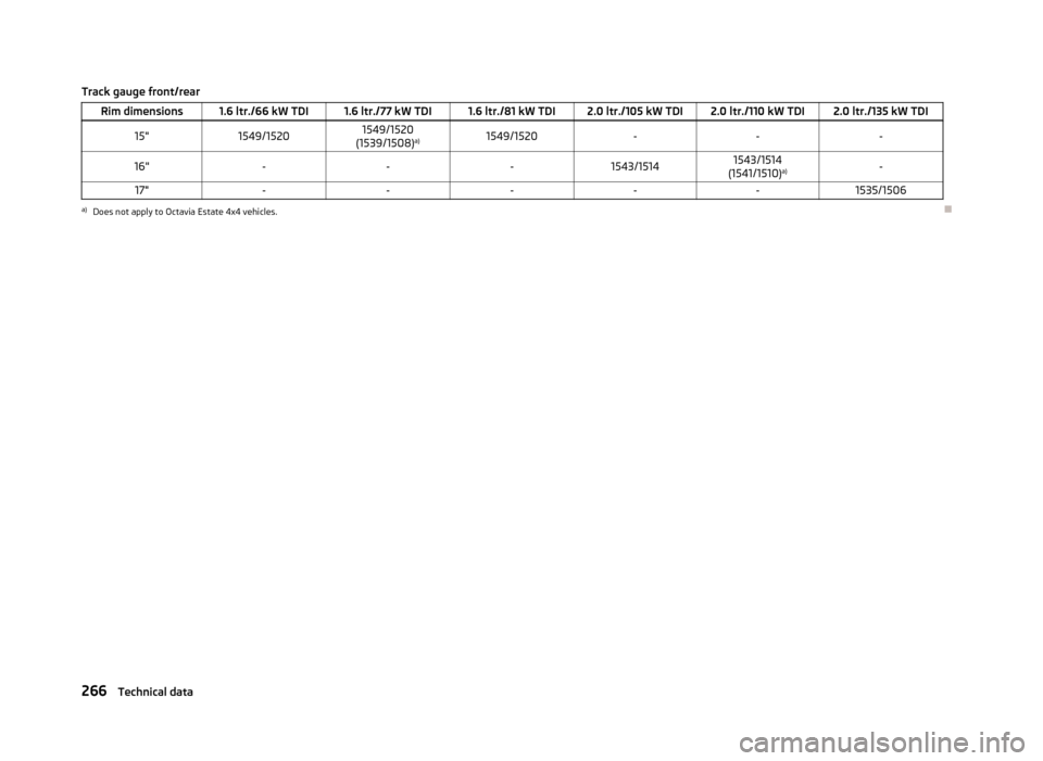
Track gauge front/rearRim dimensions1.6 ltr./66 kW TDI1.6 ltr./77 kW TDI1.6 ltr./81 kW TDI2.0 ltr./105 kW TDI2.0 ltr./110 kW TDI2.0 ltr./135 kW TDI15"1549/15201549/1520
(1539/1508) a)1549/1520---16"---1543/15141543/1514
(1541/1510) a)-17"-----1535/1506a)
Does not apply to Octavia Estate 4x4 vehicles.
266Technical data
Page 270 of 287
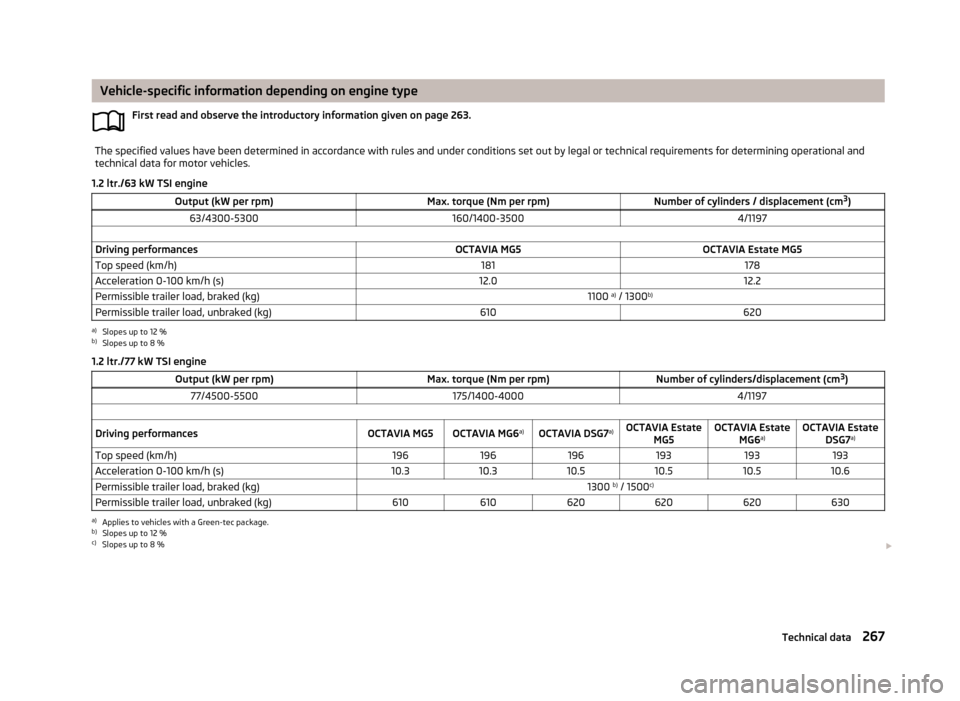
Vehicle-specific information depending on engine typeFirst read and observe the introductory information given on page 263.The specified values have been determined in accordance with rules and under conditions set out by legal or technical requirements for determining operational and
technical data for motor vehicles.
1.2 ltr./63 kW TSI engine
Output (kW per rpm)Max. torque (Nm per rpm)Number of cylinders / displacement (cm 3
)63/4300-5300160/1400-35004/1197 Driving performancesOCTAVIA MG5OCTAVIA Estate MG5Top speed (km/h)181178Acceleration 0-100 km/h (s)12.012.2Permissible trailer load, braked (kg)1100 a)
/ 1300 b)Permissible trailer load, unbraked (kg)610620a)
Slopes up to 12 %
b)
Slopes up to 8 %
1.2 ltr./77 kW TSI engine
Output (kW per rpm)Max. torque (Nm per rpm)Number of cylinders/displacement (cm 3
)77/4500-5500175/1400-40004/1197 Driving performancesOCTAVIA MG5OCTAVIA MG6 a)OCTAVIA DSG7 a)OCTAVIA Estate
MG5OCTAVIA EstateMG6a)OCTAVIA Estate
DSG7 a)Top speed (km/h)196196196193193193Acceleration 0-100 km/h (s)10.310.310.510.510.510.6Permissible trailer load, braked (kg)1300 b)
/ 1500 c)Permissible trailer load, unbraked (kg)610610620620620630a)
Applies to vehicles with a Green-tec package.
b)
Slopes up to 12 %
c)
Slopes up to 8 %
267Technical data