key SKODA SUPERB 2007 1.G / (B5/3U) User Guide
[x] Cancel search | Manufacturer: SKODA, Model Year: 2007, Model line: SUPERB, Model: SKODA SUPERB 2007 1.G / (B5/3U)Pages: 259, PDF Size: 14.71 MB
Page 40 of 259
Unlocking and locking39
Using the systemSafetyDriving TipsGeneral MaintenanceBreakdown assistanceTechnical Data
WARNING
If the vehicle is locked from the outside and the safe securing system is acti-
vated, there must not be any person in the vehicle as it is then not possible
to open either a door or a window from the inside. The locked doors make it
more difficult for rescuers to get into the vehicle in an emergency - hazard!
Note
•Operate the radio remote control only when the doors and boot lid are closed
and you have visual contact with the vehicle.
•Once in the car, you must not press the lock button of the master key before
inserting the key into the ignition lock in order to avoid the car being inadvertently
locked and, in addition, the anti-theft al arm system* being switched on. Should this
happen, press the unlock button
of the master key.
Synchonisation of the remote control
If the vehicle cannot be unlocked by actuatin g the remote control system then it is
possible that the code in the key and the control unit in the vehicle are no longer
synchronised. This can occur when the butt ons on the radio-operated key are actu-
ated a number of times outside of the operative range of the equipment or the
battery on the remote control was replaced.
This means it is necessary to synchronise the code as follows:
•Press any button on the remote control.
•pressing of the button means that the door will unlock with the key within 1
minute.
Anti-theft alarm system*
Description
The anti-theft alarm system increases the level of protection against people seeking
to break into the vehicle. The system triggers audible and visual warning signals if
an attempt is made to break into the vehicle.
How is the alarm sy stem switched on?
The anti-theft alarm system is activated automatically when the vehicle is locked
with the key on the closed driver's door or by using the remote control. It is acti-
vated 30 seconds after closing the door.
How is the alarm sy stem switched off?
The anti-theft alarm system is switched off if the vehicle is unlocked by only using
the remote control. The vehicle is automati cally locked again if the vehicle is not
opened within 30 seconds after reactivating the anti-theft alarm system.
Once you unlock the vehicle by inserting the key into the driver door you then have
to insert the key into the ignition lock and switch the ignition on within 15 seconds
after opening the door in order to deactivate the anti-theft alarm system. The
alarm will be triggered if you do not switch on the ignition within 15 seconds.
When is the alarm triggered?
The following security areas of the locked vehicle are monitored:
•Bonnet,
•Boot lid,
•Doors,
•Ignition lock,
•Vehicle interior* ⇒page 40,
•A drop in voltage of the on-board power supply.
An alarm is immediately triggered if either of the two battery terminals is discon-
nected while the anti-theft alarm system is activated.
If you unlock and open the boot lid with the key, the alarm is immediately triggered.
NKO B5 20.book Page 39 Friday, March 2, 2007 1:46 PM
Page 41 of 259

Unlocking and locking
40
How is the alarm switched off?
You switch the alarm off if you unlock the car with the radio remote control in the
key or if you switch the ignition on.
Indicator light (LED)
The LED in the top of the door trim on the driver door first of all flashes rapidly after
the car is locked, then slowly. This indi cates that the anti-theft alarm system
including the interior monitor* is activated.
Note
•The working life of the alarm siren is 5 years. More detailed information is avail-
able from your Škoda Service Partner.
•Before leaving the car, check that al l the doors, windows and the electric
sliding/tilting roof* are properly closed in order to ensure that the anti-theft alarm
system is fully operational.
•Coding of the radio remote control and the receptor part precludes the use of
the radio remote control from other vehicles.
Interior monitor*
The interior monitor detects moveme nts inside the car and then trig-
gers the alarm.
You can switch the interior monitor off if, for example, an animal or other
moving objects inside the car might trigger the alarm.
Deactivation of interior monitor
– Press the button
on the center column at the driver's side
⇒ fig. 28 .
– Lock the car.
The interior monitor is switched on agai n automatically the next time the car is
locked.
Note
You can switch off the interior mo nitor only after opening the door.
Power windows
Buttons on the driver's door
The power windows operate only when ignition is switched on.B1Z-0042HB1Z-0042HFig. 28 Interior monitor
pushbutton
B1Z-0042HB1Z-0042H
Fig. 29 Armrest on the
driver's door: Control
elements
NKO B5 20.book Page 40 Friday, March 2, 2007 1:46 PM
Page 43 of 259
Unlocking and locking
42
A button for the relevant window is provided in these doors.
Opening a window
– Press the appropriate button down and hold it until the window has
moved into the desired position.
Closing a window
– Press the appropriate button up and hold it until the window has
moved into the desired position.
WARNING
The system is fitted with a force limiter. The closing process will be stop if an
obstruction is detected and the window will open again. You should then
take particular care when closing the windows! You may otherwise suffer
severe injuries as a result of getting an arm, for example, jammed in the
window!
Note
After switching the ignition off, it is still possible to open or close the windows for a
further 10 minutes. The automatic closing and opening functions will not operate
during this time. The power windows are switched off completely once you open
the driver or front passenger door.
Window convenience operation
You can open and close the electric ally powered windows as follows
when unlocking and locking the vehicle (just closing of the sliding roof).
Opening windows with the key
– Turn the key in the lock of the driver door into the opening position or
press the opening button of the radio remote control until all the
windows are open. Closing windows with the key
– Turn the key in the lock of the driver door into the closing position or
press the closing button of the remote control until all the windows
are closed ⇒.
You can interrupt the opening or closing operation of the windows immediately by
releasing the key of the button of the remote control.
WARNING
•Obstruction protection is not active during the convenience operating
feature ⇒ in “Button in front passenger door and in rear doors” on
page 41.
•You should take particular care when closing the windows! You may
otherwise suffer severe injuries as a re sult of getting an arm, for example,
jammed in the window!
Operational faults
Electrically operated power windows do not operate
If the battery of the car has been disco nnected and then reconnected, the electri-
cally operated power windows do not oper ate. The system must be activated.
Proceed as follows in order to re-establish the function:
•turn the key in the lock of the driver d oor into the closing position and hold it
there until all of the windows are closed,
•release the key,
•Once again insert the key and turn it into the closing position for about 3
seconds.
Operation in winter
Ice accumulating on the surface of the windows during the winter may result in a
greater resistance when closing the windows and the window may stop and move
back several centimetres
Proceed as follows to close the window fully:
NKO B5 20.book Page 42 Friday, March 2, 2007 1:46 PM
Page 44 of 259
Unlocking and locking43
Using the systemSafetyDriving TipsGeneral MaintenanceBreakdown assistanceTechnical Data
•turn the key in the lock of the driver door into the closing position and hold it
there until all of the windows are closed,
•repeat this operation until the window stops.
WARNING
•Obstruction protection is not active during the closing of the windows
⇒ in “Button in front passenger door and in rear doors” on page 41.
•You should take particular care when closing the windows! You may
otherwise suffer severe injuries as a re sult of getting an arm, for example,
jammed in the window!
Electric sliding/tilting roof*
Description
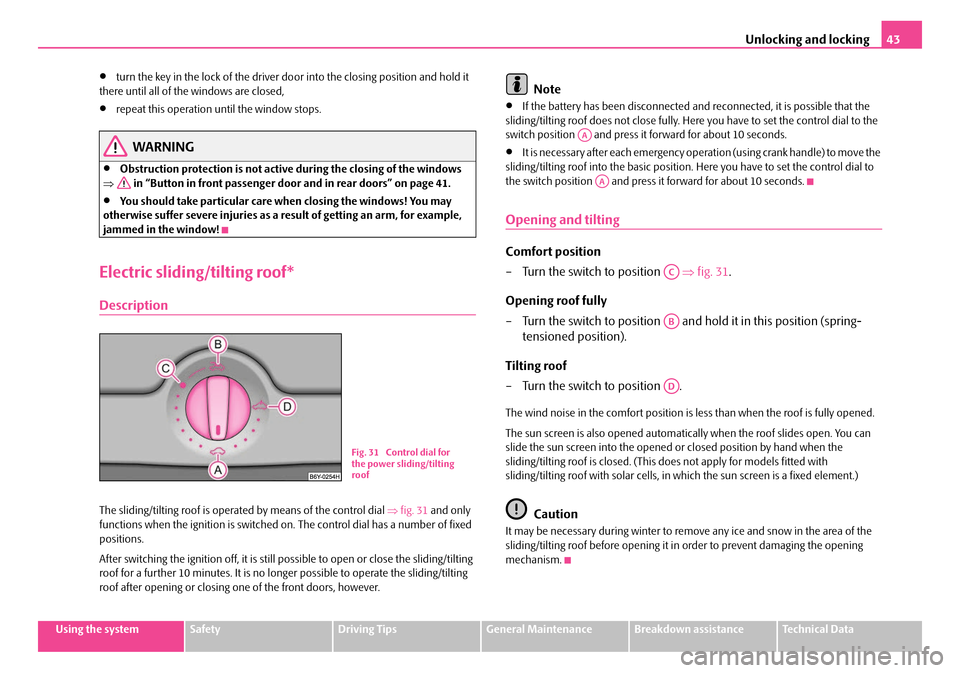
The sliding/tilting roof is operated by means of the control dial ⇒fig. 31 and only
functions when the ignition is switched on . The control dial has a number of fixed
positions.
After switching the ignition off, it is still possible to open or close the sliding/tilting
roof for a further 10 minutes. It is no long er possible to operate the sliding/tilting
roof after opening or closing on e of the front doors, however.
Note
•If the battery has been disconnected and reconnected, it is possible that the
sliding/tilting roof does not close fully. Here you have to set the control dial to the
switch position and press it forward for about 10 seconds.
•It is necessary after each emergency oper ation (using crank handle) to move the
sliding/tilting roof into the basic position. Here you have to set the control dial to
the switch position and press it forward for about 10 seconds.
Opening and tilting
Comfort position
– Turn the switch to position ⇒fig. 31 .
Opening roof fully
– Turn the switch to position and hold it in this position (spring-
tensioned position).
Tilting roof
– Turn the switch to position .
The wind noise in the comfort position is less than when the roof is fully opened.
The sun screen is also opened automatica lly when the roof slides open. You can
slide the sun screen into the opened or closed position by hand when the
sliding/tilting roof is closed. (This does not apply for models fitted with
sliding/tilting roof with solar cells, in which the sun screen is a fixed element.)
Caution
It may be necessary during winter to remo ve any ice and snow in the area of the
sliding/tilting roof before opening it in order to prevent damaging the opening
mechanism.
Fig. 31 Control dial for
the power sliding/tilting
roof
AA
AA
AC
AB
AD
NKO B5 20.book Page 43 Friday, March 2, 2007 1:46 PM
Page 45 of 259
Unlocking and locking
44
Closing
Sliding closed/closing the sliding/tilting roof
– Turn the switch to position ⇒page 43, fig. 31 .
Safety closing
The sliding/tilting roof is equipped with an overload protection system. The
sliding/tilting roof stops and moves back several centimetres when it cannot be
closed because there is something in the way (e.g. ice). You can close the
sliding/tilting roof completely without overlo ad protection by pressing the switch to
the position ⇒page 43, fig. 31 at the front for as long as it takes for the
sliding/tilting roof to shut completely ⇒.
WARNING
Close the sliding/tilting roof carefully - risk of injury!
Convenience operation
You can also close an open sliding/tilting roof from the outside.
– Turn the key in the lock of the driver door into the closing position or
press the closing button of the remote control until the sliding/tilting
roof is closed ⇒.
The closing process stops when one releases the key or the closing button.
WARNING
Close the sliding/tilting roof carefully - risk of injury! The overload protec-
tion system does not function with the convenience closing.
AA
AA
NKO B5 20.book Page 44 Friday, March 2, 2007 1:46 PM
Page 46 of 259

Unlocking and locking45
Using the systemSafetyDriving TipsGeneral MaintenanceBreakdown assistanceTechnical Data
Emergency operation
You can close and/or open the sliding/ti lting roof by hand if the system is
defect.
– Position the flat blade of a screwdriver (car tool kit) carefully against the rear edge of the cover of the power roof drive ⇒fig. 32 .
– Pull the cover down.
– Insert an Allen key, Group 4, up to the stop into the opening and close and/or open the sliding/tilting roof ⇒fig. 33 . – Press on the cover again by first of all inserting the plastic lugs and
then pushing the cover up.
– Have the fault rectified by a specialist workshop.
Note
It is necessary after each emergency op eration (using Allen key) to move the
sliding/tilting roof into the basic position . Here you have to press the control dial
forward to switch position ⇒page 43, fig. 31 for about 10 seconds.
B1Z-0042HB1Z-0042H
Fig. 32 Detail of the
headliner: point for posi-
tioning screwdriver
Fig. 33 Detail of the
headliner: Emergency
operation
AA
NKO B5 20.book Page 45 Friday, March 2, 2007 1:46 PM
Page 47 of 259
Lights and Visibility
46
Lights and Visibility
Lights
Switching lights on and off
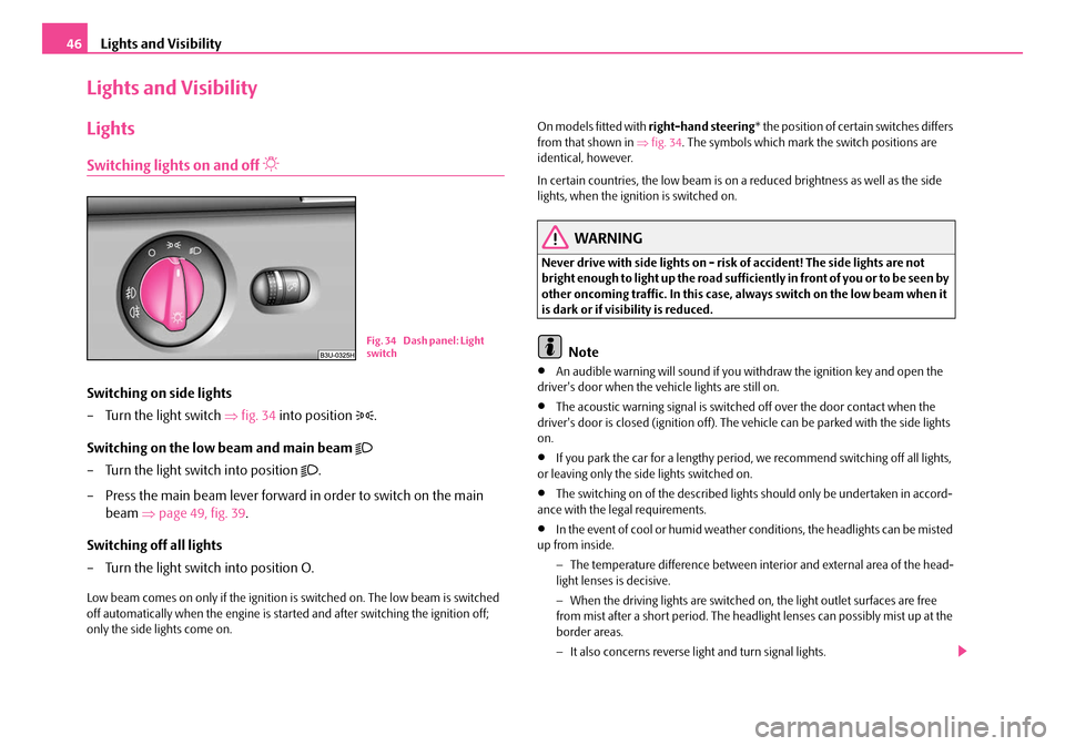
Switching on side lights
– Turn the light switch ⇒fig. 34 into position
.
Switching on the low beam and main beam
– Turn the light switch into position .
– Press the main beam lever forward in order to switch on the main beam ⇒page 49, fig. 39.
Switching off all lights
– Turn the light switch into position O.
Low beam comes on only if the ignition is switched on. The low beam is switched
off automatically when the engine is star ted and after switching the ignition off;
only the side lights come on. On models fitted with
right-hand steering* the position of certain switches differs
from that shown in ⇒fig. 34 . The symbols which mark the switch positions are
identical, however.
In certain countries, the low beam is on a reduced brightness as well as the side
lights, when the ignition is switched on.
WARNING
Never drive with side lights on - risk of accident! The side lights are not
bright enough to light up the road sufficiently in front of you or to be seen by
other oncoming traffic. In this case, always switch on the low beam when it
is dark or if visibility is reduced.
Note
•An audible warning will sound if you withdraw the ignition key and open the
driver's door when the vehicle lights are still on.
•The acoustic warning signal is switched off over the door contact when the
driver's door is closed (ignition off). The vehicle can be parked with the side lights
on.
•If you park the car for a lengthy period, we recommend switching off all lights,
or leaving only the side lights switched on.
•The switching on of the described lights should only be undertaken in accord-
ance with the legal requirements.
•In the event of cool or humid weather conditions, the headligh ts can be misted
up from inside.
−The temperature difference between interior and external area of the head-
light lenses is decisive.
− When the driving lights are switched on, the light outlet surfaces are free
from mist after a short period. The headli ght lenses can possibly mist up at the
border areas.
− It also concerns reverse light and turn signal lights.
B1Z-0042HB1Z-0042HFi g. 3 4 D ash pan el: Lig ht
switch
NKO B5 20.book Page 46 Friday, March 2, 2007 1:46 PM
Page 50 of 259
Lights and Visibility49
Using the systemSafetyDriving TipsGeneral MaintenanceBreakdown assistanceTechnical Data
The turn signal and main beam lever
The parking lights and headlight flas her are also switched on and off
using the turn signal and main beam lever.
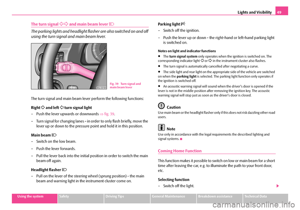
The turn signal and main beam lever perform the following functions:
Right
and left turn signal light
– Push the lever upwards or downwards ⇒fig. 39 .
– Turn signal for changing lanes - in or der to only flash briefly, move the
lever up or down to the pressure po int and hold it in this position.
Main beam
– Switch on the low beam.
– Push the lever forwards.
– Pull the lever back into the initial position in order to switch the main beam off again.
Headlight flasher
– Pull on the lever of the steering wheel (sprung position) - the main beam and warning light in the instrument cluster come on. Parking light
– Switch off the ignition.
– Push the lever up or down - the right-hand or left-hand parking light
is switched on.
Notes on light and indicator functions
•The turn signal system only operates when the ignition is switched on. The
corresponding indicator light or in the instrument cluster also flashes.
•The turn signal is automatically cancelled after negotiating a curve.
•The side light and rear light on the appropriate side of the vehicle are switched
on when the parking light is selected. The parking light function only operates if
the ignition is switched off.
•An acoustic warning signal will sound when the driver's door is opened if the
lever is not in the middle position after removing the ignition key. The acoustic
warning signal will stop just as soon as the driver's door is closed.
Caution
Use main beam or the headlight flasher only if this does not risk dazzling other road
users.
Note
Use only in accordance with the legal requirements the described lighting and
signal systems.
Coming Home Function
This function makes it possible to switch on low or main beam for a short
time after leaving the car, e.g. to illuminate the path to your front door,
etc.
Selecting function
– Switch off the light.
Fig. 39 Turn signal and
main beam lever
NKO B5 20.book Page 49 Friday, March 2, 2007 1:46 PM
Page 51 of 259
Lights and Visibility
50
– Switch off the ignition.
– Flash one time with the headlights.
– Open the door, the low beam lights up.
If you shift the lever into the main be am position, the main beam lights up.
If the door remains open, the ligh t remains on for about 3 minutes.
If the door is closed, the light remains on for about 30 seconds.
Interior lighting
Front interior lighting and storage compartment on front
passenger side
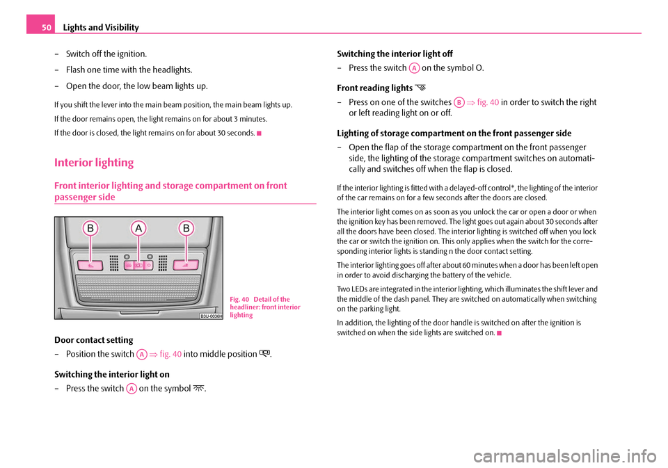
Door contact setting
– Position the switch ⇒ fig. 40 into middle position
.
Switching the interior light on
– Press the switch on the symbol
. Switching the interior light off
– Press the switch on the symbol O.
Front reading lights
– Press on one of the switches
⇒fig. 40 in order to switch the right
or left reading light on or off.
Lighting of storage compartme nt on the front passenger side
– Open the flap of the storage compartment on the front passenger side, the lighting of the storage compartment switches on automati-
cally and switches off when the flap is closed.
If the interior lighting is fitted with a dela yed-off control*, the lighting of the interior
of the car remains on for a few seconds after the doors are closed.
The interior light comes on as soon as yo u unlock the car or open a door or when
the ignition key has been removed. The light goes out again about 30 seconds after
all the doors have been closed. The interior lighting is switched off when you lock
the car or switch the ignition on. This on ly applies when the switch for the corre-
sponding interior lights is standing n the door contact setting.
The interior lighting goes off after about 60 minutes when a door has been left open
in order to avoid discharging the battery of the vehicle.
Two LEDs are integrated in the interior li ghting, which illuminates the shift lever and
the middle of the dash panel. They are switched on automatically when switching
on the parking light.
In addition, the lighting of the door handle is switched on after the ignition is
switched on when the side lights are switched on.
B1Z-0042HB1Z-0042H
Fig. 40 Detail of the
headliner: front interior
lighting
AA
AA
AA
AB
NKO B5 20.book Page 50 Friday, March 2, 2007 1:46 PM
Page 61 of 259
Seats and Stowage
60
Adjusting height of seat
– Lift the seat if required by pulling or pumping lever ⇒page 59,
fig. 53 upwards.
– Lower the seat if required by pushing or pumping lever down- wards.
Adjust the angle of the seat backrest
– Relieve any pressure on the backrest (do not lean on it) and turn the handwheel to adjust the angle of the backrest.
Adjusting Lumbar support
– Turn the handwheel until you have set the most comfortable curvature of the seat upholstery in the area of your spine.
The driver's seat should be adjusted in such a way that the pedals can be pressed
to the floor with slightly bent legs.
The backrest on the driver's seat should be adjusted in such a way that the upper
point of the steering wheel can be easi ly reached with slightly bent arms.
WARNING
•Only adjust the driver seat when the ve hicle is stationary - risk of injury!
•Take care when adjusting the seat! Adjusting the seat without care can
lead to bruises or injuries.
•The backrests must not be angled too far back when driving otherwise
this will affect proper operation of th e seat belts and of the airbag system -
risk of injury!
Adjusting front seats electrically*
Adjusting seats
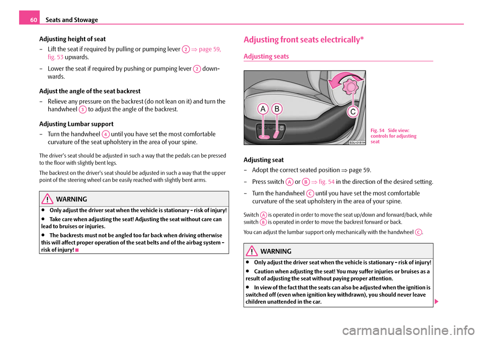
Adjusting seat
– Adopt the correct seated position ⇒page 59.
– Press switch or ⇒fig. 54 in the direction of the desired setting.
– Turn the handwheel until you have set the most comfortable curvature of the seat upholstery in the area of your spine.
Switch is operated in order to move the seat up/down and forward/back, while
switch is operated in order to move the backrest forward or back.
You can adjust the lumbar support only mechanically with the handwheel .
WARNING
•Only adjust the driver seat when the vehicle is stationary - risk of injury!
•Caution when adjusting the seat! You ma y suffer injuries or bruises as a
result of adjusting the seat without paying proper attention.
•In view of the fact that the seats can also be adjusted when the ignition is
switched off (even when ignition key withdrawn), you should never leave
children unattended in the car.
A2
A2
A3
A4
B1Z-0042HB1Z-0042H
Fig. 54 Side view:
controls for adjusting
seat
AAAB
AC
AAAB
AC
NKO B5 20.book Page 60 Friday, March 2, 2007 1:46 PM