towing SKODA YETI 2011 1.G / 5L Owner's Manual
[x] Cancel search | Manufacturer: SKODA, Model Year: 2011, Model line: YETI, Model: SKODA YETI 2011 1.G / 5LPages: 252, PDF Size: 3.61 MB
Page 6 of 252
Head airbags . . . . . . . . . . . . . . . . . . . . . . . . . . . . . . . . . . . . . . 143
Deactivating an airbag . . . . . . . . . . . . . . . . . . . . . . . . . . . . . 144
Transporting children safely . . . . . . . . . . . . . . . . . . . . . . 146
What you should know about transporting children! . 146
Child seat . . . . . . . . . . . . . . . . . . . . . . . . . . . . . . . . . . . . . . . . . 148
Attaching a child seat using the “ISOFIX” system . . . . 151
Attaching child seat using the “Top Tether” system . . 152
Driving Tips . . . . . . . . . . . . . . . . . . . . . . . . . . . . . . . . . . . 153
Intelligent technology . . . . . . . . . . . . . . . . . . . . . . . . . . . . . 153
Electronic stability programme (ESP) . . . . . . . . . . . . . . . . 153
Brakes . . . . . . . . . . . . . . . . . . . . . . . . . . . . . . . . . . . . . . . . . . . . 155
Brake booster . . . . . . . . . . . . . . . . . . . . . . . . . . . . . . . . . . . . . 156
Antilock brake system (ABS) . . . . . . . . . . . . . . . . . . . . . . . . 157
Brake Assist . . . . . . . . . . . . . . . . . . . . . . . . . . . . . . . . . . . . . . . 157
Uphill Start Assist . . . . . . . . . . . . . . . . . . . . . . . . . . . . . . . . . 158
Electromechanical power steering . . . . . . . . . . . . . . . . . . 158
Tyre pressure monitoring system . . . . . . . . . . . . . . . . . . . 158
Diesel particle filter (diesel engine) . . . . . . . . . . . . . . . . . 159
Off-road . . . . . . . . . . . . . . . . . . . . . . . . . . . . . . . . . . . . . . . . . . 160
Driving and the environment . . . . . . . . . . . . . . . . . . . . . 162
The first 1 500 kilometres and then afterwards . . . . . . 162
Catalytic converter . . . . . . . . . . . . . . . . . . . . . . . . . . . . . . . . . 162
Driving in an economical and environmentally
conscious manner . . . . . . . . . . . . . . . . . . . . . . . . . . . . . . . . . 163
Environmental compatibility . . . . . . . . . . . . . . . . . . . . . . . . 166
Motoring abroad . . . . . . . . . . . . . . . . . . . . . . . . . . . . . . . . . . . 167
Avoiding damage to your vehicle . . . . . . . . . . . . . . . . . . . 167
Driving through bodies of water on roads . . . . . . . . . . . 167
Off-road driving . . . . . . . . . . . . . . . . . . . . . . . . . . . . . . . . . . . 168
Towing a trailer . . . . . . . . . . . . . . . . . . . . . . . . . . . . . . . . . . . . 178
Towing a trailer . . . . . . . . . . . . . . . . . . . . . . . . . . . . . . . . . . . 178
General Maintenance . . . . . . . . . . . . . . . . . . . . . 180
Taking care of your vehicle and cleaning the
vehicle . . . . . . . . . . . . . . . . . . . . . . . . . . . . . . . . . . . . . . . . . . . . . . 180
General . . . . . . . . . . . . . . . . . . . . . . . . . . . . . . . . . . . . . . . . . . . 180
Care of the exterior of vehicle . . . . . . . . . . . . . . . . . . . . . . 180
Care of the interior of vehicle . . . . . . . . . . . . . . . . . . . . . . . 184 Fuel
. . . . . . . . . . . . . . . . . . . . . . . . . . . . . . . . . . . . . . . . . . . . . . . . . 186
Petrol . . . . . . . . . . . . . . . . . . . . . . . . . . . . . . . . . . . . . . . . . . . . . 186
Diesel . . . . . . . . . . . . . . . . . . . . . . . . . . . . . . . . . . . . . . . . . . . . . 187
Refuelling . . . . . . . . . . . . . . . . . . . . . . . . . . . . . . . . . . . . . . . . . 187
Inspecting and Replenishing . . . . . . . . . . . . . . . . . . . . . . 189
Engine compartment . . . . . . . . . . . . . . . . . . . . . . . . . . . . . . 189
Engine oil . . . . . . . . . . . . . . . . . . . . . . . . . . . . . . . . . . . . . . . . . 191
Cooling system . . . . . . . . . . . . . . . . . . . . . . . . . . . . . . . . . . . . 193
Brake fluid . . . . . . . . . . . . . . . . . . . . . . . . . . . . . . . . . . . . . . . . 195
Battery . . . . . . . . . . . . . . . . . . . . . . . . . . . . . . . . . . . . . . . . . . . 196
Windshield washer system . . . . . . . . . . . . . . . . . . . . . . . . . 199
Wheels and Tyres . . . . . . . . . . . . . . . . . . . . . . . . . . . . . . . . . . 201
Wheels . . . . . . . . . . . . . . . . . . . . . . . . . . . . . . . . . . . . . . . . . . . 201
Accessories, changes and replacement of parts . 207
General . . . . . . . . . . . . . . . . . . . . . . . . . . . . . . . . . . . . . . . . . . . 207
Breakdown assistance . . . . . . . . . . . . . . . . . . . 208
Breakdown assistance . . . . . . . . . . . . . . . . . . . . . . . . . . . . 208
Space for first-aid box and warning triangle . . . . . . . . . 208
Fire extinguisher . . . . . . . . . . . . . . . . . . . . . . . . . . . . . . . . . . 208
Vehicle tool kit . . . . . . . . . . . . . . . . . . . . . . . . . . . . . . . . . . . . 208
Spare wheel . . . . . . . . . . . . . . . . . . . . . . . . . . . . . . . . . . . . . . . 209
Changing a wheel . . . . . . . . . . . . . . . . . . . . . . . . . . . . . . . . . 209
Tyre repair kit . . . . . . . . . . . . . . . . . . . . . . . . . . . . . . . . . . . . . 213
Jump-starting . . . . . . . . . . . . . . . . . . . . . . . . . . . . . . . . . . . . . 216
The vehicle . . . . . . . . . . . . . . . . . . . . . . . . . . . . . . . . . . . . . . . . 217
Fuses and light bulbs . . . . . . . . . . . . . . . . . . . . . . . . . . . . . . 220
Electric fuses . . . . . . . . . . . . . . . . . . . . . . . . . . . . . . . . . . . . . . 220
Bulbs . . . . . . . . . . . . . . . . . . . . . . . . . . . . . . . . . . . . . . . . . . . . . 223
Technical data . . . . . . . . . . . . . . . . . . . . . . . . . . . . . . . 228
Technical data . . . . . . . . . . . . . . . . . . . . . . . . . . . . . . . . . . . . . 228
General information . . . . . . . . . . . . . . . . . . . . . . . . . . . . . . . 228
Used abbreviations . . . . . . . . . . . . . . . . . . . . . . . . . . . . . . . . 228
Performances . . . . . . . . . . . . . . . . . . . . . . . . . . . . . . . . . . . . . 228
Weight . . . . . . . . . . . . . . . . . . . . . . . . . . . . . . . . . . . . . . . . . . . . 228
Identification details . . . . . . . . . . . . . . . . . . . . . . . . . . . . . . . 229 Fuel consumption according to the ECE standards and
EU guidelines
. . . . . . . . . . . . . . . . . . . . . . . . . . . . . . . . . . . . . 229
Dimensions . . . . . . . . . . . . . . . . . . . . . . . . . . . . . . . . . . . . . . . 230
Other information . . . . . . . . . . . . . . . . . . . . . . . . . . . . . . . . . 230
Engine oil specifications . . . . . . . . . . . . . . . . . . . . . . . . . . . 231
Engine 1.2 l/77 kW TSI - EU5 . . . . . . . . . . . . . . . . . . . . . . . . 232
Engine 1.4 l/90 kW TSI - EU5 . . . . . . . . . . . . . . . . . . . . . . . . 233
Engine 1.8 ltr./118 kW TSI - EU2, EU5 (1.8 ltr./112 kW TSI
- EU5)
. . . . . . . . . . . . . . . . . . . . . . . . . . . . . . . . . . . . . . . . . . . . . 234
Engine 1.6 l/77 kW TDI CR - EU5 . . . . . . . . . . . . . . . . . . . . . 235
Engine 2.0 l/81 kW TDI CR - EU5 . . . . . . . . . . . . . . . . . . . . 236
Engine 2.0 l/103 kW TDI CR - EU4, EU5 . . . . . . . . . . . . . . 237
Engine 2.0 l/125 kW TDI CR - EU5 . . . . . . . . . . . . . . . . . . . 238
Multi-purpose vehicles (AF) . . . . . . . . . . . . . . . . . . . . . . . . 239
. . . . . . . . . . . . . . . . . . . . . . . . . . . . . . . . . . . . . . . . . . . . . . . . . . 239
Index . . . . . . . . . . . . . . . . . . . . . . . . . . . . . . . . . . . . . . . . . . . . . 2404
Table of Contents
Page 25 of 252
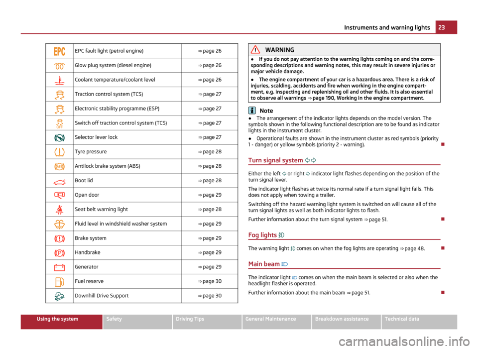
EPC fault light (petrol engine)
⇒ page 26
Glow plug system (diesel engine)
⇒ page 26
Coolant temperature/coolant level
⇒ page 26
Traction control system (TCS)
⇒ page 27
Electronic stability programme (ESP)
⇒ page 27
Switch off traction control system (TCS)
⇒ page 27
Selector lever lock
⇒ page 27
Tyre pressure
⇒ page 28
Antilock brake system (ABS)
⇒ page 28
Boot lid
⇒ page 28
Open door
⇒ page 29
Seat belt warning light
⇒ page 28
Fluid level in windshield washer system
⇒ page 29
Brake system
⇒ page 29
Handbrake
⇒ page 29
Generator
⇒ page 29
Fuel reserve
⇒ page 30
Downhill Drive Support
⇒ page 30 WARNING
● If you do not pay attention to the warning lights coming on and the corre-
sponding descriptions and warning notes, this may result in severe injuries or
major vehicle damage.
● The engine compartment of your car is a hazardous area. There is a risk of
injuries, scalding, accidents and fire when working in the engine compart-
ment, e.g. inspecting and replenishing oil and other fluids. It is also essential
to observe all warnings ⇒
page 190, Working in the engine compartment. Note
● The arrangement of the indicator lights depends on the model version. The
symbols shown in the following functional description are to be found as indicator
lights in the instrument cluster.
● Operational faults are shown in the instrument cluster as red symbols (priority
1 - danger) or yellow symbols (priority 2 - warning).
Turn signal system Either the left
or right
indicator light flashes depending on the position of the
turn signal lever.
The indicator light flashes at twice its normal rate if a turn signal light fails. This
does not apply when towing a trailer.
Switching off the hazard warning light system is switched on will cause all of the
turn signal lights as well as both indicator lights to flash.
Further information about the turn signal system ⇒
page 51.
Fog lights The warning light
comes on when the fog lights are operating
⇒
page 48.
Main beam The indicator light
comes on when the main beam is selected or also when the
headlight flasher is operated.
Further information about the main beam ⇒
page 51. 23
Instruments and warning lights Using the system Safety Driving Tips General Maintenance Breakdown assistance Technical data
Page 40 of 252
Display of the locking
The turn signal lights flash once to confirm that the vehicle has been correctly
locked.
If the vehicle is locked by pressing the button
3 and some doors or the boot lid
are not closed, the turn signal lights flash only after closing. WARNING
If the vehicle is locked from the outside and the safe securing system is acti-
vated, there must not be any person in the vehicle as it is then not possible to
open either a door or a window from the inside. The locked doors make it
more difficult for rescuers to get into the vehicle in an emergency - hazard! Note
● Operate the radio remote control only when the doors and boot lid are closed
and you have visual contact with the vehicle.
● Once in the car, you must not press the lock button of the radio remote con-
trol before inserting the key into the ignition lock in order to avoid the car being
inadvertently locked and the alarm system being switched on. Should this happen,
press the unlock button of the radio remote control.
Synchonisation of the remote control If the vehicle cannot be unlocked by actuating the remote control system then it
is possible that the code in the key and the control unit in the vehicle are no lon-
ger synchronised. This can occur when the buttons on the radio-operated key are
actuated a number of times outside of the operative range of the equipment or
the battery on the remote control was replaced.
This means it is necessary to synchronise the code as follows:
● press any button on the remote control;
● pressing of the button means that the door will unlock with the key within 1
minute. Anti-theft alarm system
Description The anti-theft alarm system increases the level of protection against people seek-
ing to break into the vehicle. The system triggers audible and visual warning sig-
nals if an attempt is made to break into the vehicle.
How is the alarm system activated?
The anti-theft alarm system is activated automatically when the vehicle is locked
with the key on the driver's door or by using the radio remote control. It is activa-
ted 30 seconds after locking the door.
How is the alarm system deactivated?
The anti-theft alarm system is deactivated if the vehicle is unlocked by only using
the radio remote control. The anti-theft alarm system is reactivated if the vehicle
is not opened within 30 seconds after transmitting the radio signal.
Once you unlock the vehicle by inserting the key into the driver door you then
have to insert the key into the ignition lock and switch the ignition on within 15
seconds after opening the door in order to deactivate the anti-theft alarm system.
The alarm will be triggered if you do not switch on the ignition within 15 seconds.
When is the alarm triggered?
The following security areas of the locked vehicle are monitored:
● Bonnet,
● Boot lid,
● Doors,
● Ignition lock,
● Vehicle inclination ⇒ page 39,
● Vehicle interior ⇒ page 39,
● A drop in voltage of the on-board power supply,
● Socket of the factory-fitted towing device.
An alarm is immediately triggered if either of the two battery terminals is discon- nected while the anti-theft alarm system is activated.
How is the alarm switched off?
You switch the alarm off if you unlock the vehicle with the radio remote control or
if you switch the ignition on. £38
Locking and Unlocking
Page 41 of 252
Note
● The working life of the alarm siren is 6 years. More detailed information is
available by a specialist garage.
● Before leaving the car, check that all the doors, windows and the electric slid-
ing/tilting roof are properly closed in order to ensure that the anti-theft alarm sys-
tem is fully operational.
● Coding of the radio remote control and the receiver unit precludes the use of
the radio remote control from other vehicles.
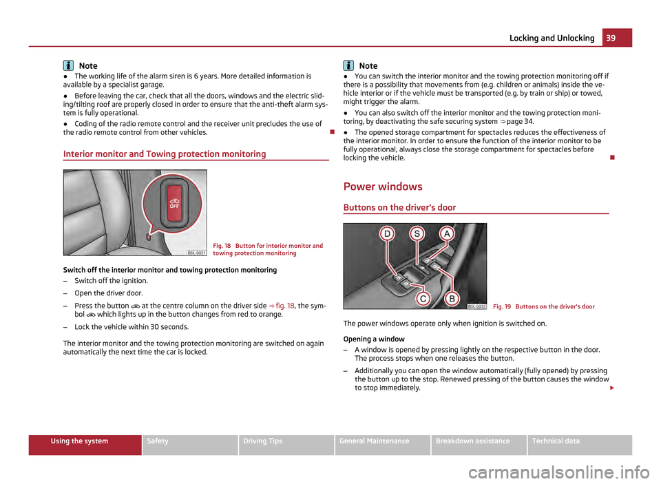
Interior monitor and Towing protection monitoring Fig. 18 Button for interior monitor and
towing protection monitoring
Switch off the interior monitor and towing protection monitoring
– Switch off the ignition.
– Open the driver door.
– Press the button
at the centre column on the driver side ⇒ fig. 18 , the sym-
bol
which lights up in the button changes from red to orange.
– Lock the vehicle within 30 seconds.
The interior monitor and the towing protection monitoring are switched on again
automatically the next time the car is locked. Note
● You can switch the interior monitor and the towing protection monitoring off if
there is a possibility that movements from (e.g. children or animals) inside the ve-
hicle interior or if the vehicle must be transported (e.g. by train or ship) or towed,
might trigger the alarm.
● You can also switch off the interior monitor and the towing protection moni-
toring, by deactivating the safe securing system ⇒
page 34.
● The opened storage compartment for spectacles reduces the effectiveness of
the interior monitor. In order to ensure the function of the interior monitor to be
fully operational, always close the storage compartment for spectacles before
locking the vehicle.
Power windows Buttons on the driver's door Fig. 19 Buttons on the driver's door
The power windows operate only when ignition is switched on.
Opening a window
– A window is opened by pressing lightly on the respective button in the door.
The process stops when one releases the button.
– Additionally you can open the window automatically (fully opened) by pressing
the button up to the stop. Renewed pressing of the button causes the window
to stop immediately. £ 39
Locking and Unlocking Using the system Safety Driving Tips General Maintenance Breakdown assistance Technical data
Page 51 of 252
The warning light
lights up in the instrument cluster when the fog lights are
switched on ⇒
page 22.
Fog lights with the function “CORNER” The fog lights with the function “CORNER” are designed for a bet-
ter illumination of the surrounding area near the vehicle when
corning, parking etc.
The fog lights with the function
“CORNER” are adjusted according to the steering
angle or after switching on the turn signal light 1)
in the following circumstances:
● the vehicle is stationary and the engine is running or it moves with a speed of
maximum 40 km/h;
● the daylight driving lights are not switched on;
● the low beam is switched on or the light switch is in the position
and the
intensity of the ambient light causes the low beam to be switched on;
● the fog lights are not switched on;
● no reverse gear is engaged. Note
If you engage the reverse gear during the active function “CORNER”, both fog
lights illuminate.
Rear fog light Switching on the rear fog light
–
First of all turn the light switch into position or ⇒
fig. 26 .
– Pull the light switch into position 2 .
The warning light
lights up in the instrument cluster when the rear fog light is
switched on ⇒ page 22.
Only the rear fog light of the trailer lights up if the vehicle has a factory-fitted
towing device or a towing device from ŠKODA original accessories and when you
are towing a trailer which is fitted with the rear fog light. The rear fog light is located in the rear light array on the driver's side. CAUTION
The rear fog light should only be switched on if visibility is particularly poor (con-
form with any varying legal provisions) to avoid dazzling vehicles behind your ve-
hicle.
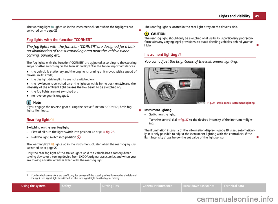
Instrument lighting You can adjust the brightness of the instrument lighting.
Fig. 27 Dash panel: Instrument lighting
Instrument lighting
– Switch on the light.
– Turn the control dial ⇒
fig. 27 to the desired intensity of the instrument light-
ing.
The illumination intensity of the Information display ⇒ page 18 is set automatical-
ly. It is only possible to adjust the instrument lighting with the control dial if the
light intensity drops below the set value of the light sensor. 1)
If both switch on versions are conflicting, for example if the steering wheel is turned to the left and
the right turn signal light is switched on, the turn signal light has the higher priority. 49
Lights and Visibility Using the system Safety Driving Tips General Maintenance Breakdown assistance Technical data
Page 73 of 252
Note
Tyre pressure must be adjusted to the load ⇒ page 201.
Vehicles of category N1 On vehicles of the category N1, which are not fitted with a protective grille, a lash-
ing set which complies with the standard EN
12195 (1 - 4) must be used for fasten-
ing the load.
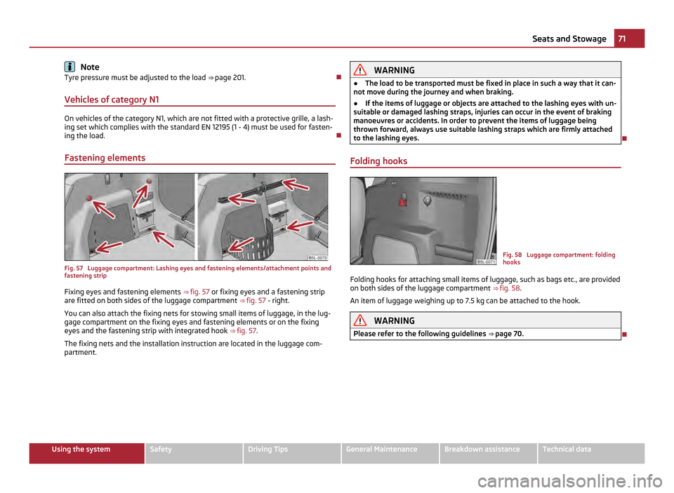
Fastening elements Fig. 57 Luggage compartment: Lashing eyes and fastening elements/attachment points and
fastening strip
Fixing eyes and fastening elements ⇒ fig. 57 or fixing eyes and a fastening strip
are fitted on both sides of the luggage compartment ⇒
fig. 57 - right.
You can also attach the fixing nets for stowing small items of luggage, in the lug-
gage compartment on the fixing eyes and fastening elements or on the fixing
eyes and the fastening strip with integrated hook ⇒ fig. 57.
The fixing nets and the installation instruction are located in the luggage com-
partment. WARNING
● The load to be transported must be fixed in place in such a way that it can-
not move during the journey and when braking.
● If the items of luggage or objects are attached to the lashing eyes with un-
suitable or damaged lashing straps, injuries can occur in the event of braking
manoeuvres or accidents. In order to prevent the items of luggage being
thrown forward, always use suitable lashing straps which are firmly attached
to the lashing eyes.
Folding hooks Fig. 58 Luggage compartment: folding
hooks
Folding hooks for attaching small items of luggage, such as bags etc., are provided
on both sides of the luggage compartment ⇒ fig. 58 .
An item of luggage weighing up to 7.5 kg can be attached to the hook. WARNING
Please refer to the following guidelines ⇒ page 70. 71
Seats and Stowage Using the system Safety Driving Tips General Maintenance Breakdown assistance Technical data
Page 77 of 252
Remove carrier rails
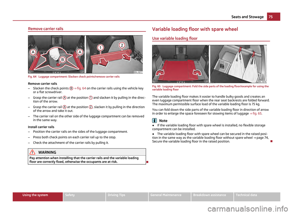
Fig. 64 Luggage compartment: Slacken check points/remove carrier rails
Remove carrier rails
– Slacken the check points B
⇒ fig. 64 on the carrier rails using the vehicle key
or a flat screwdriver.
– Grasp the carrier rail A at the position
1 and slacken it by pulling in the direc-
tion of the arrow.
– Grasp the carrier rail A at the position
2 , slacken it by pulling in the direction
of the arrow and take it out.
– The carrier rail on the other side of the luggage compartment can be removed
in the same way.
Install carrier rails
– Position the carrier rails on the sides of the luggage compartment.
– Press both check points on each carrier rail up to the stop.
– Check the attachment of the carrier rails by pulling it. WARNING
Pay attention when installing that the carrier rails and the variable loading
floor are correctly fixed, otherwise the occupants are at risk. Variable loading floor with spare wheel
Use variable loading floor
Fig. 65 Luggage compartment: Fold the side parts of the loading floor/example for using the
variable loading floor
The variable loading floor makes it easier to handle bulky goods and creates an
even luggage compartment floor when the rear seat backrests are folded forward.
The maximum permissible surface load of the variable loading floor is 75
kg.
You can fold down the side parts of the variable loading floor in direction of arrow
in order to enlarge the space foreseen for stowing items of luggage ⇒ fig. 65 . Note
● If the variable loading floor with spare wheel is installed, no flexible storage
compartment can be installed.
● The variable loading floor with spare wheel can be secured in the raised posi-
tion in the same way as the variable loading floor without spare wheel ⇒
page 74,
Secure the variable loading floor in the raised position. 75
Seats and Stowage Using the system Safety Driving Tips General Maintenance Breakdown assistance Technical data
Page 86 of 252
Stowage compartment in rear centre console
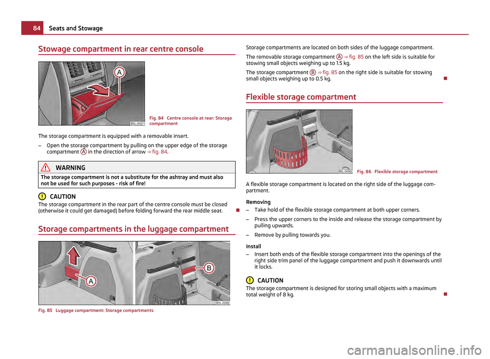
Fig. 84 Centre console at rear: Storage
compartment
The storage compartment is equipped with a removable insert.
– Open the storage compartment by pulling on the upper edge of the storage
compartment A in the direction of arrow
⇒ fig. 84 . WARNING
The storage compartment is not a substitute for the ashtray and must also
not be used for such purposes - risk of fire! CAUTION
The storage compartment in the rear part of the centre console must be closed
(otherwise it could get damaged) before folding forward the rear middle seat.
Storage compartments in the luggage compartment Fig. 85 Luggage compartment: Storage compartments Storage compartments are located on both sides of the luggage compartment.
The removable storage compartment
A ⇒ fig. 85
on the left side is suitable for
stowing small objects weighing up to 1.5 kg.
The storage compartment B ⇒
fig. 85 on the right side is suitable for stowing
small objects weighing up to 0.5 kg.
Flexible storage compartment Fig. 86 Flexible storage compartment
A flexible storage compartment is located on the right side of the luggage com-
partment.
Removing
– Take hold of the flexible storage compartment at both upper corners.
– Press the upper corners to the inside and release the storage compartment by
pulling upwards.
– Remove by pulling towards you.
Install
– Insert both ends of the flexible storage compartment into the openings of the
right side trim panel of the luggage compartment and push it downwards until
it locks. CAUTION
The storage compartment is designed for storing small objects with a maximum
total weight of 8 kg. 84
Seats and Stowage
Page 105 of 252
The handbrake warning light
lights up when the handbrake is applied, provided
the ignition is on.
A warning signal sounds and the following text appears in the Information display
if you have inadvertently driven off with the handbrake applied:
Release parking brake!
The handbrake warning is activated if you drive at a speed of more than 6 km/h
for more than 3 seconds. WARNING
● Please note that the handbrake must be fully released. A handbrake which
is only partially released can result in the rear brakes overheating which will
have a negative effect on the operation of the brake system - risk of accident!
In addition this can result in premature wear of the rear brake pads.
● Never leave children unattended in the vehicle. The children might, for ex-
ample, release the handbrake or take the vehicle out of gear. The vehicle
might then move off - risk of accident! CAUTION
After the car has come to a stop, always first of all apply the handbrake firmly be-
fore then additionally engaging a gear (manual gearbox) or moving the selector
lever into position P (automatic gearbox).
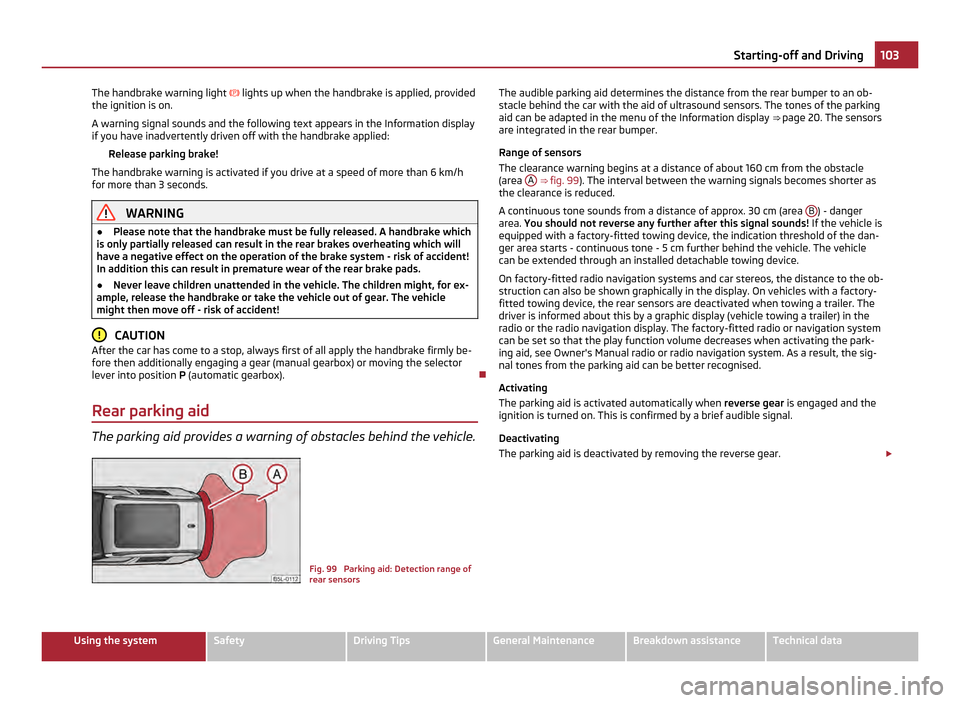
Rear parking aid The parking aid provides a warning of obstacles behind the vehicle.
Fig. 99 Parking aid: Detection range of
rear sensorsThe audible parking aid determines the distance from the rear bumper to an ob-
stacle behind the car with the aid of ultrasound sensors. The tones of the parking
aid can be adapted in the menu of the Information display
⇒
page 20. The sensors
are integrated in the rear bumper.
Range of sensors
The clearance warning begins at a distance of about 160 cm from the obstacle
(area A ⇒
fig. 99 ). The interval between the warning signals becomes shorter as
the clearance is reduced.
A continuous tone sounds from a distance of approx. 30 cm (area B ) - danger
area. You should not reverse any further after this signal sounds! If the vehicle is
equipped with a factory-fitted towing device, the indication threshold of the dan-
ger area starts -
continuous tone - 5 cm further behind the vehicle. The vehicle
can be extended through an installed detachable towing device.
On factory-fitted radio navigation systems and car stereos, the distance to the ob-
struction can also be shown graphically in the display. On vehicles with a factory-
fitted towing device, the rear sensors are deactivated when towing a trailer. The
driver is informed about this by a graphic display (vehicle towing a trailer) in the
radio or the radio navigation display. The factory-fitted radio or navigation system
can be set so that the play function volume decreases when activating the park-
ing aid, see Owner's Manual radio or radio navigation system. As a result, the sig-
nal tones from the parking aid can be better recognised.
Activating
The parking aid is activated automatically when reverse gear is engaged and the
ignition is turned on. This is confirmed by a brief audible signal.
Deactivating
The parking aid is deactivated by removing the reverse gear. £ 103
Starting-off and Driving Using the system Safety Driving Tips General Maintenance Breakdown assistance Technical data
Page 106 of 252
WARNING
● The parking aid is not a substitute for the driver paying proper attention
and it is always the driver's responsibility to take care when parking the vehi-
cle or carrying out similar manoeuvres.
● You should therefore satisfy yourself, before reversing, that there is no
small obstacle, such as a rock, thin post, trailer drawbar etc., behind your vehi-
cle. Such an obstacle might not be within the range detected by the sensors.
● Under certain circumstances, surfaces of certain objects and types of
clothing cannot reflect the signal of the parking aid. Thus, these objects or
people who wear such clothing are not recognised by the sensors of the park-
ing aid. Note
● The parking aid does not operate if you are towing a trailer (applies to models
which feature a factory-fitted towing device).
● If a warning signal sounds for about 3 seconds after switching the ignition on
and engaging reverse gear, and there is no obstacle close to your car, this indi-
cates a system fault. Have the fault rectified by a specialist workshop.
● The sensors must be kept clean and free of ice to enable the parking aid to
operate properly.
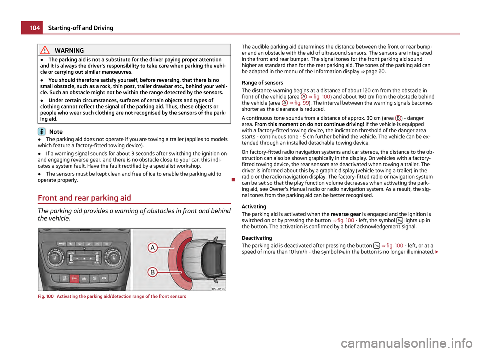
Front and rear parking aid The parking aid provides a warning of obstacles in front and behind
the vehicle. Fig. 100 Activating the parking aid/detection range of the front sensors The audible parking aid determines the distance between the front or rear bump-
er and an obstacle with the aid of ultrasound sensors. The sensors are integrated
in the front and rear bumper. The signal tones for the front parking aid sound
higher as standard than for the rear parking aid. The tones of the parking aid can
be adapted in the menu of the Information display ⇒ page 20.
Range of sensors
The distance warning begins at a distance of about 120 cm from the obstacle in
front of the vehicle (area A ⇒
fig. 100 ) and about 160 cm from the obstacle behind
the vehicle (area A ⇒ fig. 99
). The interval between the warning signals becomes
shorter as the clearance is reduced.
A continuous tone sounds from a distance of approx. 30 cm (area B ) - danger
area. From this moment on do not continue driving! If the vehicle is equipped
with a factory-fitted towing device, the indication threshold of the danger area
starts -
continuous tone - 5 cm further behind the vehicle. The vehicle can be ex-
tended through an installed detachable towing device.
On factory-fitted radio navigation systems and car stereos, the distance to the ob-
struction can also be shown graphically in the display. On vehicles with a factory-
fitted towing device, the rear sensors are deactivated when towing a trailer. The
driver is informed about this by a graphic display (vehicle towing a trailer) in the
radio or the radio navigation display. The factory-fitted radio or navigation system
can be set so that the play function volume decreases when activating the park-
ing aid, see Owner's Manual radio or radio navigation system. As a result, the sig-
nal tones from the parking aid can be better recognised.
Activating
The parking aid is activated when the reverse gear is engaged and the ignition is
switched on or by pressing the button ⇒ fig. 100 - left, the symbol lights up in
the button. The activation is confirmed by a brief acknowledgement signal.
Deactivating
The parking aid is deactivated after pressing the button
⇒
fig. 100 - left, or at a
speed of more than 10 km/h - the symbol in the button is no longer illuminated. £104
Starting-off and Driving