check engine SSANGYONG KORANDO 1997 Service Repair Manual
[x] Cancel search | Manufacturer: SSANGYONG, Model Year: 1997, Model line: KORANDO, Model: SSANGYONG KORANDO 1997Pages: 2053, PDF Size: 88.33 MB
Page 794 of 2053
OM600 ENGINE CONTROLS 1F3 -- 37
D AEW OO M Y_2000
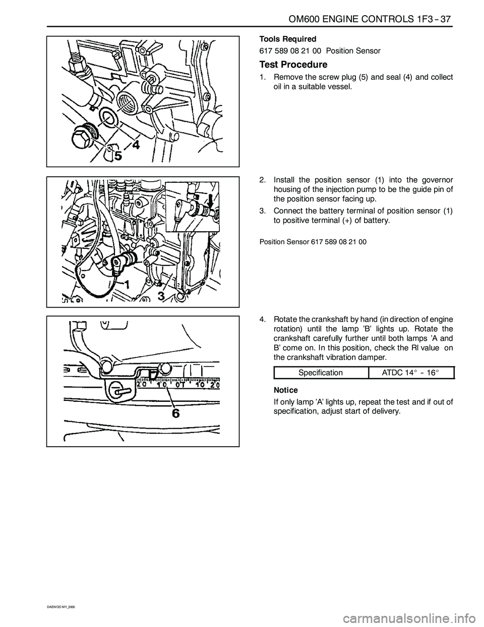
Tools Required
617 589 08 21 00 Position Sensor
Test Procedure
1. Remove the screw plug (5) and seal (4) and collect
oil in a suitable vessel.
2. Install the position sensor (1) into the governor
housing of the injection pump to be the guide pin of
the position sensor facing up.
3. Connect the battery terminal of position sensor (1)
to positive terminal (+) of battery.
Position Sensor 617 589 08 21 00
4. Rotate the crankshaft by hand (in direction of engine
rotation) until the lamp ’B’ lights up. Rotate the
crankshaft carefully further until both lamps ’A and
B’ come on. In this position, check the Rl value on
the crankshaft vibration damper.
SpecificationAT DC 1 4_-- 1 6_
Notice
If only lamp ’A’ lights up, repeat the test and if out of
specification, adjust start of delivery.
Page 797 of 2053
1F3 -- 40 OM600 ENGINE CONTROLS
D AEW OO M Y_2000
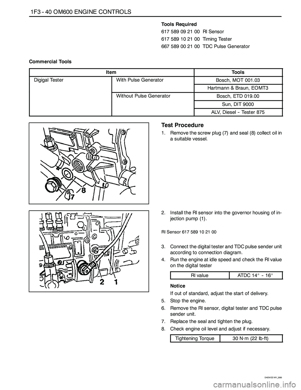
Tools Required
617 589 09 21 00 Rl Sensor
617589102100 TimingTester
667589002100 TDCPulseGenerator
Commercial Tools
ItemTools
Digigal TesterWith Pulse GeneratorBosch, MOT 001.03gg
Hartmann & Braun, EOMT3
Without Pulse GeneratorBosch, ETD 019.00
Sun, DIT 9000
ALV, Diesel -- Tester 875
Test Procedure
1. Remove the screw plug (7) and seal (8) collect oil in
a suitable vessel.
2. Install the Rl sensor into the governor housing of in-
jection pump (1).
Rl Sensor 617 589 10 21 00
3. Connect the digital tester and TDC pulse sender unit
according to connection diagram.
4. Run the engine at idle speed and check the Rl value
on the digital tester
Rl valueAT DC 1 4_-- 1 6_
Notice
If out of standard, adjust the start of delivery.
5. Stop the engine.
6. Remove the Rl sensor, digital tester and TDC pulse
sender unit.
7. Replace the seal and tighten the plug.
8. Check engine oil level and adjust if necessary.
Tightening Torque30 N∙m (22 lb-ft)
Page 807 of 2053

1F3 -- 50 OM600 ENGINE CONTROLS
D AEW OO M Y_2000
11. Assemble the plastic clip (8).
12. Connect the vacuum line (13, 14).
13. Connect the connecting rod (9).
14. Connect the accelerator control damper (10).
(Manual transmission vehicle)
15. Install the chain tensioner.
16. Install the vacuum pump.
17. Check the start of delivery.
18. Adjust the idle speed.
Page 821 of 2053
SSANGYONG MY2002
2B-2 WHEEL ALIGNMENT
FOUR WHEEL ALIGNMENT
The first responsibility of engineering is to design safe
steering and suspension systems. Each component
must be strong enough to withstand and absorb extreme
punishment. Both the steering system and the front
and the rear suspension must function geometrically
with the body mass.
The steering and the suspension systems require that
the front wheels self-return and that the tire rolling effor t
and the road friction be held to a negligible force in
order to allow the customer to direct the vehicle with
the least effort and the most comfort.
A complete wheel alignment check should include mea-
surements of the rear toe and camber.
Four-wheel alignment assures that all four wheels will
be running in precisely the same direction.
When the vehicle is geometrically aligned, fuel economy
and tire life are at their peak, and steering and perfor
mance are maximized.
TOE-IN
Toe-in is the turning in of the tires, while toe-out is the
turning out of the tires from the geometric centerline or
thrust line. The toe ensures parallel rolling of the wheels.
The toe serves to offset the small deflections of the
wheel support system which occur when the vehicle is
rolling forward. The specified toe angle is the setting
which achieves 0 degrees of toe when the vehicle is
moving.
Incorrect toe-in or toe-out will cause tire wear and re
duced fuel economy. As the individual steering and
sus-pension components wear from vehicle mileage,
additional toe will be needed to compensate for the
wear.
Always correct the toe dimension last.
CASTER
Caster is the tilting of the uppermost point of the steering
axis either forward or backward from the vertical when
viewed from the side of the vehicle. A backward tilt is
positive, and a forward tilt is negative. Caster influences
directional control of the steering but does not affect
tire wear. Weak springs or overloading a vehicle will
affect caster. One wheel with more positive caster will
pull toward the center of the car. This condition will
cause the car to move or lean toward the side with the
least amount of positive caster. Caster is measured in
degrees.
CAMBER
Camber is the tilting of the top of the tire from the
vertical when viewed from the front of the vehicle. When
the tires tilt outward, the camber is positive. When the
tires tilt inward, the camber is negative. The camber
angle is measured in degrees from the vertical. Camber
in-fluences both directional control and tire wear.
If the vehicle has too much positive camber, the outside
shoulder of the tire will wear. If the vehicle has too
much negative camber, the inside shoulder of the tire
will wear.
DESCRIPTION AND OPERATION
Page 923 of 2053
HYDRAULIC BRAKES 4A-3
SSANGYONG MY2002
DIAGNOSTIC INFORMATION AND PROCEDURES
BRAKE SYSTEM TESTING
Brakes should be tested on a dry, clean, reasonably
smooth and level roadway. A true test of brake perfor-
mance cannot be made if the roadway is wet, greasy,
or covered with loose dirt which can cause tires not to
grip the road unequally. Testing also will be inaccurate
on a crowned roadway because the wheels tend to
bounce.
Test the brakes at different vehicle speeds with both
light-and heavy-pedal pressure; however, avoid locking
the brakes and sliding the tires. Locked brakes and
slid-ing tires do not indicate brake efficiency since
heavily braked but turning wheels will stop the vehicle
in less distance than locked brakes. More tire-to-road
friction is present with a heavily braked, turning tire
than with a sliding tire.
Because of the high deceleration capability, a firmer
pedal may be felt at higher deceleration levels.
There are three major external conditions that affect
brake performance:
•Tires having unequal contact and grip of the road
will cause unequal braking. Tires must be equally
inflated, and the tread pattern of the right and the
left tires must be approximately equal.
Unequal loading of the vehicle can affect the brake
performance since the most heavily loaded wheels
require more braking power, and thus more braking
effort, than the others.
Misalignment of the wheels, particularly conditions
of excessive camber and caster, will cause the
brakes to pull to one side.
To check for brake fluid leaks, hold constant foot pres-
sure on the pedal with the engine running at idle and
the shift lever in NEUTRAL. If the pedal gradually falls
away with the constant pressure, the hydraulic system
may be leaking. Perform a visual check to confirm any
suspected leaks.
Check the master cylinder fluid level. While a slight
drop in the reservoir level results from normal lining
wear, an abnormally low level indicates a leak in the
system. The hydraulic system may be leaking either
internally or externally. Refer to the procedure below
to check the master cylinder. The system may appear
to pass this test while still having a slight leak. If the
fluid level is normal, check the vacuum booster pushrod
length. If an incorrect pushrod length is found, adjust
or replace the rod.Check the master cylinder using the following proce
dure:
Check for a cracked master cylinder casting or a
brake fluid leak around the master cylinder. Leaks
are indicated only if there is at least one drop of
fluid. A damp condition is not abnormal.
Check for a binding pedal linkage and for an
incorrect pushrod length. If both of these parts are
in satisfactory condition, disassemble the master
cylinder and check for an elongated or swollen
primary cylinder or piston seals. If swollen seals
are found, substandard or contaminated brake fluid
should be suspected. If contaminated brake fluid
is found, all the components should be
disassembled and cleaned, and all the rubber
components should be replaced. All of the pipes
must also be flushed.
Improper brake fluid, or mineral oil or water in the fluid,
may cause the brake fluid to boil or cause deterioration
of the rubber components. If the primary piston cups in
the master cylinder are swollen, the rubber parts have
deteriorated.
If deterioration of the rubber is evident, disassemble
all the hydraulic parts and wash the parts with alcohol.
Dry these parts with compressed air before reassembly
to keep the alcohol out of the system. Replace all the
rubber parts in the system, including the hoses. When
working on the brake mechanisms, check for fluid on
the linings. If excessive fluid is found, replace the
linings.
If the master cylinder piston seals are in satisfactory
condition, check for leaks or excessive heat conditions.
If these conditions are not found, drain the fluid, flush
the master cylinder with brake fluid, refill the master
cylinder, and bleed the system.
BRAKE HOSE INSPECTION
The hydraulic brake hoses should be inspected at least
twice a year. The brake hose assembly should be
checked for road hazard damage, cracks, chafing of
the outer cover, and for leaks or blisters. Inspect the
hoses for proper routing and mounting. A brake hose
that rubs on a suspension component will wear and
eventually fail. A light and a mirror may be needed for
an adequate inspection. If any of the above conditions
are observed on the brake hose, adjust or replace the
hose as necessary.
Page 925 of 2053
HYDRAULIC BRAKES 4A-5
SSANGYONG MY2002
Value(s)
-
-
-
-
-
-
-
-
-
-
-
-
-
-
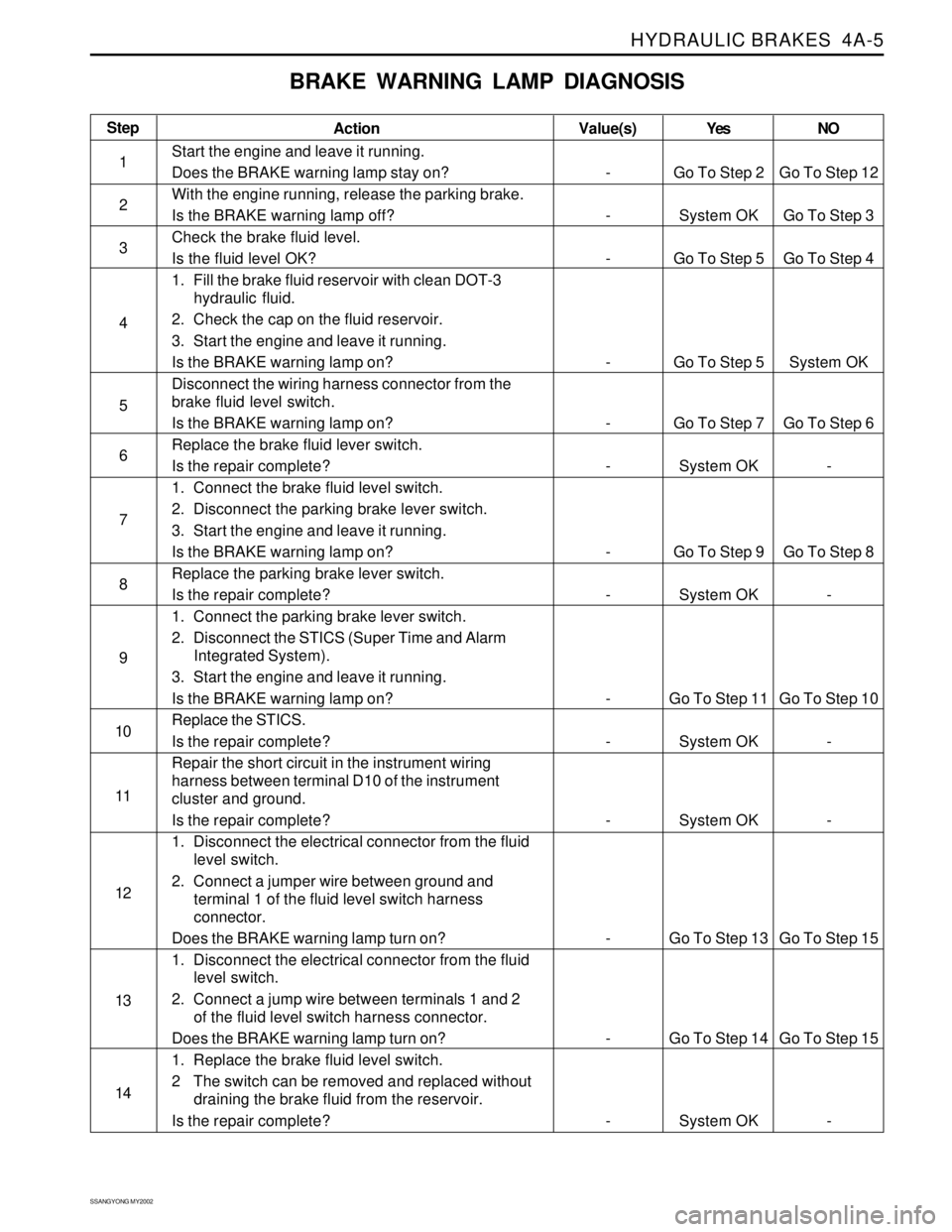
BRAKE WARNING LAMP DIAGNOSIS
Step
1
2
3
4
5
6
7
8
9
10
11
12
13
14Action
Start the engine and leave it running.
Does the BRAKE warning lamp stay on?
With the engine running, release the parking brake.
Is the BRAKE warning lamp off?
Check the brake fluid level.
Is the fluid level OK?
1. Fill the brake fluid reservoir with clean DOT-3
hydraulic fluid.
2. Check the cap on the fluid reservoir.
3. Start the engine and leave it running.
Is the BRAKE warning lamp on?
Disconnect the wiring harness connector from the
brake fluid level switch.
Is the BRAKE warning lamp on?
Replace the brake fluid lever switch.
Is the repair complete?
1. Connect the brake fluid level switch.
2. Disconnect the parking brake lever switch.
3. Start the engine and leave it running.
Is the BRAKE warning lamp on?
Replace the parking brake lever switch.
Is the repair complete?
1. Connect the parking brake lever switch.
2. Disconnect the STICS (Super Time and Alarm
Integrated System).
3. Start the engine and leave it running.
Is the BRAKE warning lamp on?
Replace the STICS.
Is the repair complete?
Repair the short circuit in the instrument wiring
harness between terminal D10 of the instrument
cluster and ground.
Is the repair complete?
1. Disconnect the electrical connector from the fluid
level switch.
2. Connect a jumper wire between ground and
terminal 1 of the fluid level switch harness
connector.
Does the BRAKE warning lamp turn on?
1. Disconnect the electrical connector from the fluid
level switch.
2. Connect a jump wire between terminals 1 and 2
of the fluid level switch harness connector.
Does the BRAKE warning lamp turn on?
1. Replace the brake fluid level switch.
2 The switch can be removed and replaced without
draining the brake fluid from the reservoir.
Is the repair complete?Yes
Go To Step 2
System OK
Go To Step 5
Go To Step 5
Go To Step 7
System OK
Go To Step 9
System OK
Go To Step 11
System OK
System OK
Go To Step 13
Go To Step 14
System OKNO
Go To Step 12
Go To Step 3
Go To Step 4
System OK
Go To Step 6
-
Go To Step 8
-
Go To Step 10
-
-
Go To Step 15
Go To Step 15
-
Page 947 of 2053
SSANGYONG MY2002
4C-4 POWER BOOSTER
DIAGNOSTIC INFORMATION AND PROCEDURES
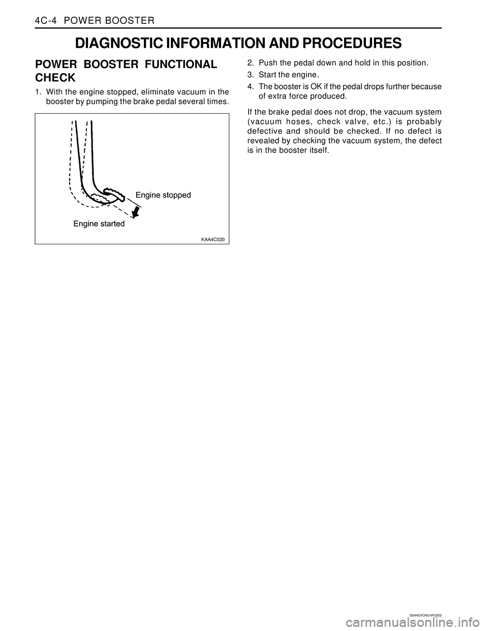
KAA4C020
2. Push the pedal down and hold in this position.
3. Start the engine.
4. The booster is OK if the pedal drops further because
of extra force produced.
If the brake pedal does not drop, the vacuum system
(vacuum hoses, check valve, etc.) is probably
defective and should be checked. If no defect is
revealed by checking the vacuum system, the defect
is in the booster itself.POWER BOOSTER FUNCTIONAL
CHECK
1. With the engine stopped, eliminate vacuum in the
booster by pumping the brake pedal several times.
Page 1067 of 2053

SSANGYONG MY2002
4F-84 ABS AND TCS
DIAGNOSTIC TROUBLE CODE (DTC) 28
LOW VOLTAGE FAULT
KAA4F240
Circuit Description
Proper operation of the electronic brake control module
(EBCM) requires a certain minimum voltage. The EBCM
monitors the ignition feed circuit to determine if the
voltage falls below a minimum level.
Diagnosis
This test checks for battery output, proper grounding,
blown fuses, faulty ignition switch, and problems in the
circuitry.
Cause(s)
The battery is defective.
There is a defective ground connection.
A connector is damaged.
A wire is broken or shorted.
A fuse is blown.
The ignition switch is malfunctioning.Fail Action
ABS action is disabled during the period of low voltage,
and the ABS warning lamp is ON for the remainder of
the ignition cycle. If the failure is intermittent, the EBCM
will enable the system at the next ignition cycle and
set a history DTC 28.
Test Description
The number(s) below refer to step(s) on the diagnostic
table.
1. This step determines whether there is voltage at
the battery and at the high current source.
7. This step checks for voltage at the ignition 1
source.
15. This step begins the check for voltage at the EBCM
end of the ABS harness.
Diagnostic Aids
It is very important to perform a thorough inspection of
the wiring and the connectors. Failure to do so may re-
sult in misdiagnosis, causing part replacement with the
reappearance of the malfunction.
Step
1
2
3
Action
Go to Step 3
System OK
Go to Step 4Go to Step 2
-
Go to Step 7 11 - 14v
-
-
Check the voltage at the battery.
Is the voltage within the specified value?
Charge or replace the battery, as required.
Is the repair complete?
Check fuse EF11 in the engine fuse block.
Is the fuse blown?
DTC 28 - Low Voltage Fault
Value(s) Yes No
Page 1068 of 2053

ABS AND TCS 4F-85
SSANGYONG MY2002
Step
4
5
6
7
8
9
10
11
12
13
DTC 28 - Low Voltage Fault (Cont’d)
Action
Go to Step 5
System OK
System OK
Go to Step 8
Go to Step 9
System OK
System OK
Go to Step 12
Go to Step 13
System OKGo to Step 6
-
-
Go to Step 11
Go to Step 10
-
-
Go to Step 15
Go to Step 14
- -
-
-
-
-
-
-
-
-
-
1. Replace fuse EF11.
2. Turn the ignition to ON.
Does the fuse blow again?
1. Turn the ignition to OFF.
2. Trace the BLK/WHT wires in the ABS wiring
harness from terminal 8 of C104 at the engine fuse
block to F19 in the I/P fuse block.
3. Repair any short circuit found along this path.
Is the repair complete?
1. Turn the ignition to OFF.
2. Install the scan tool.
3. Clear all DTCs.
4. Road test the vehicle.
Does DTC 28 reset?
Check fuse F19 in the I/P fuse block.
Is the fuse blown?
1. Replace fuse F19.
2. Turn the ignition to ON.
Does the fuse blow again?
1. Turn the ignition to OFF.
2. Trace the WHT/RED wires in the ABS Wiring
harness from fuse F19 to terminal 50 of the EBCM
connector.
3. Repair any short circuit found along this path.
Is the repair complete?
1. Turn the ignition to OFF.
2. Install the scan tool.
3. Clear all DTCs.
4. Rood test the vehicle.
Does DTC 28 reset?
Check fuse F29 in the I/P fuse block.
Is fuse F29 blown?
1. Replace fuse F29.
2. Turn the ignition to ON.
Does fuse F29 blow again?
1. Turn the ignition to OFF.
2. Trace the WHT/RED wire from fuse F19 to terminal
1 of the EBCM connector.
3. Repair any short circuit found along this path.
Is the repair complete?
Value(s) Yes No
Page 1089 of 2053
SSANGYONG MY2002
4G-2 PARKING BRAKE
DESCRIPTION AND OPERATION
BRAKE CALIPER
This braking system uses a BRAKE warning light lo-
cated in the instrument panel cluster.
The following conditions will activate the BRAKE lamp:
•The parking brake is applied when the ignition is
ON. The lamp will turn off when the parking brake
is released.
The fluid level is below the minimum mark in the
master cylinder reservoir. The lamp will turn off when
the fluid level is above the minimum.
As a test of the lamp circuit, the BRAKE lamp will
glow dimly when the ignition is ON, even if the
parking brake is off and fluid level is above the
minimum. The lamp will turn off when the engine is
started. When the brake is firmly applied, the parking
brake should hold the vehicle with ample pedal
travel remaining.
Check for frayed cables, rust, etc. or any condition
that may inhibit present (or future) free movement of
the parking brake lever assembly.