SSANGYONG KORANDO 1997 Service Repair Manual
KORANDO 1997
SSANGYONG
SSANGYONG
https://www.carmanualsonline.info/img/67/57502/w960_57502-0.png
SSANGYONG KORANDO 1997 Service Repair Manual
Page 750 of 2053
OM600 ENGINE COOLING 1D3 -- 15
D AEW OO M Y_2000
Removal & Installation Procedure
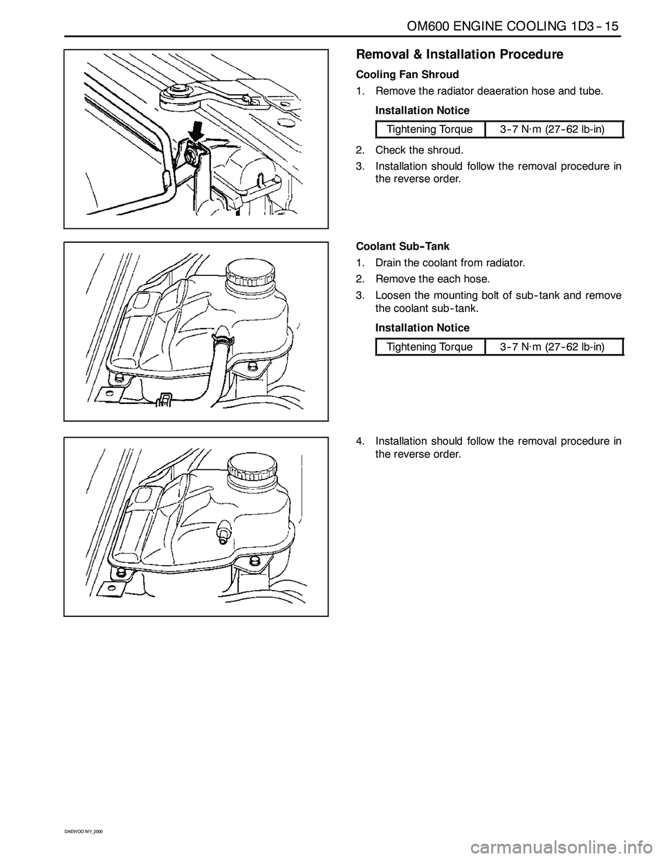
Cooling Fan Shroud
1. Remove the radiator deaeration hose and tube.
Installation Notice
Tightening Torque3--7 N∙m (27-- 62 lb-in)
2. Check the shroud.
3. Installation should follow the removal procedure in
the reverse order.
Coolant Sub-- Tank
1. Drain the coolant from radiator.
2. Remove the each hose.
3. Loosen the mounting bolt of sub-- tank and remove
the coolant sub-- tank.
Installation Notice
Tightening Torque3--7 N∙m (27-- 62 lb-in)
4. Installation should follow the removal procedure in
the reverse order.
Page 766 of 2053
1F3 -- 4 OM600 ENGINE CONTROLS
D AEW OO M Y_2000
FUEL TANK
1 Fuel Tank
2 The Sender of Fuel Tank
3 2-- way Check Valve
4 Pre Filter
5 Front Fuel Filler Neck
6 Rear Fuel Filler Neck
7 Fuel Supply Tube8 Fuel Return Tube
9 Filter Hose
10 Fuel Tank Hose
11 Fuel Filler Cap
12 Clip
13 Clip
Page 768 of 2053
OM600 ENGINE CONTROLS 1F3 -- 11
D AEW OO M Y_2000
Test Procedure
1. Remove the fuel filter (1) and keep the filter not to be
damaged from running engine.
2. Remove the vacuum line from ancillaries connection
(2).
3. Connect the vacuum tester (3) to the ancillaries con-
nection (2).
Vacuum Tester 201 589 13 21 00
4. Run the engine at idle and check vacuum pressure
after 30 sec.
Standard>70mbar
Notice
If out of standard, replace the vacuum pump.
5. Remove the vacuum tester.
6. Connect the vacuum line to the ancillaries connec-
tion.
7. Install the fuel filter.
Page 772 of 2053
OM600 ENGINE CONTROLS 1F3 -- 15
D AEW OO M Y_2000
IDLE SPEED ADJUSTMENT
Service Data
EngineIdle Speed
OM661LA Engine750 -- 850 rpm
OM662LA Engine720 -- 820 rpm
Tools Required
667 589 00 21 00 TDC Pulse Generato
Commercial Tool
Digital Testere.g. Bosch, MOT 001.03g
Sun, DIT 9000
Adjustment Procedure
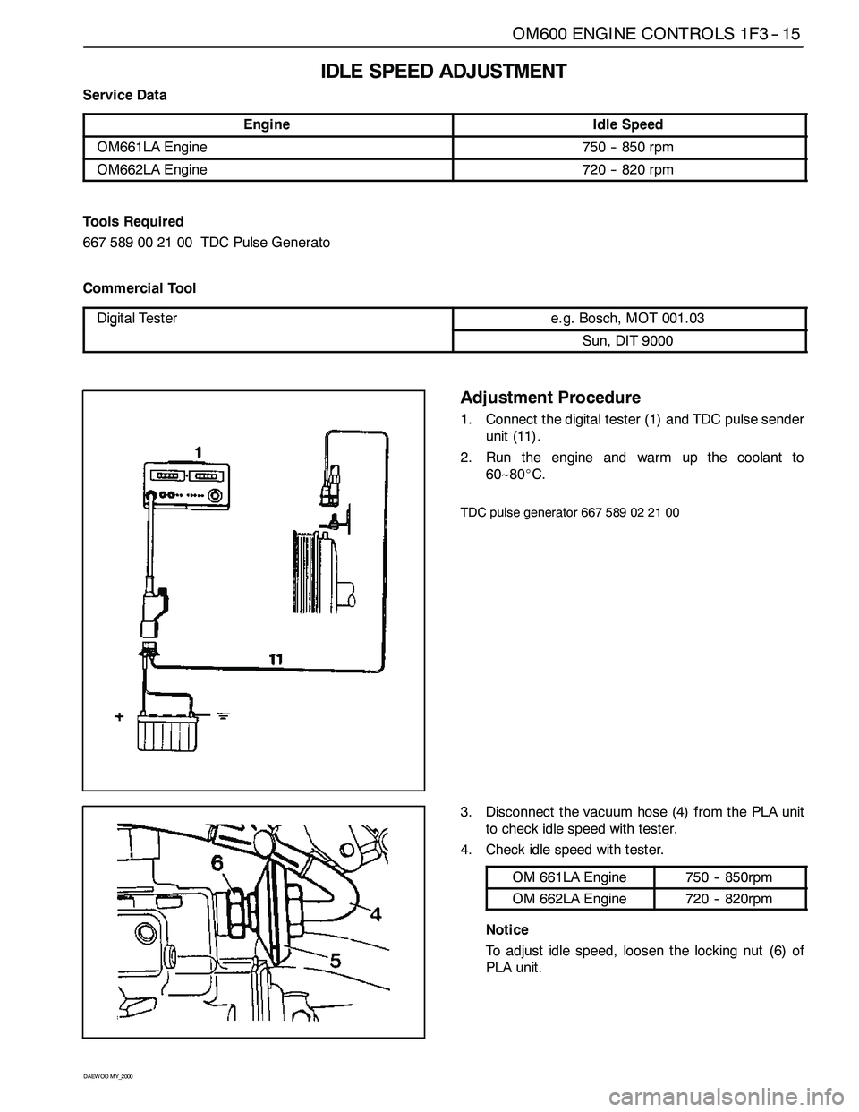
1. Connect the digital tester (1) and TDC pulse sender
unit (11).
2. Run the engine and warm up the coolant to
60~80_C.
TDC pulse generator 667 589 02 21 00
3. Disconnect the vacuum hose (4) from the PLA unit
to check idle speed with tester.
4. Check idle speed with tester.
OM 661LA Engine750 -- 850rpm
OM 662LA Engine720 -- 820rpm
Notice
To adjust idle speed, loosen the locking nut (6) of
PLA unit.
Page 773 of 2053
1F3 -- 16 OM600 ENGINE CONTROLS
D AEW OO M Y_2000
5. Ensure not to damage the idle spring in the governor
and adjust idle speed by turning the PLA unit (5)
slowly.
ClockwiseRPM Decrease
CounterclockwiseRPM Increase
Notice
Do not rotate the PLA unit over 1/2 turn from the
position marking. If do, idle spring in the governor
will be severely damaged.
6. After adjustment, tighten the locking nut and place
the position marking with different color of paint.
Notice
If there are no changes in idle speed with PLA unit
adjustment, perform the service at a BOSCH Ser-
vice Center.
7. Connect the vacuum pump to the PLA vacuum unit
and build up vacuum approx. 500mbar. If engine
rpm increases by approx. 100rpm, It is normal.
Vacuum Pump 001 589 73 21 00
8. Connect the vacuum line (4).
9. Switch on all ancillaries and check the idle speed.
Page 785 of 2053
1F3 -- 28 OM600 ENGINE CONTROLS
D AEW OO M Y_2000
7. Check the fuel injection nozzle and adjust opening
pressure if necessary.
Opening pressure adjustment
Disassemble the fuel injection nozzle and replace
the steel washer (2).
Notice
Each 0.05mm thickness of the washer results in a
pressure difference of approx. 3bar.
Page 786 of 2053
OM600 ENGINE CONTROLS 1F3 -- 29
D AEW OO M Y_2000
REMOVAL AND INSTALLATION OF INJECTION TIMING DEVICE
Preceding Work : Removal of vacuum pump
1 Cylinder Head Cover
2 Bolt 10N∙m (89 lb-in) .....................
3 Gasket Replace..........................
4 Fuel Injection Pump
5 Seal Replace.............................
6 Screw Plug 30N∙m (22 lb-ft) ................
7OilPan
8 Locking Pin
9 Injection Timing Device10 Washer
11 Bolt (Left -- Hand Thread) 46N∙m (34 lb-ft) ....
12 Camshaft Sprocket
13 Washer
14 12-- Sided Stretch Bolt
Check, 25N∙m (18 lb-ft) +90_ ..............
15 Timing Chain
16 Seal
17 Chain Tensioner 80N∙m (59 lb-ft) ............
Page 787 of 2053
1F3 -- 30 OM600 ENGINE CONTROLS
D AEW OO M Y_2000
Tools Required
601589000800 Flange
601 589 05 21 00 Locking Screw
116 589 20 33 00 Sliding Hammer
116 589 02 34 00 Threaded Bolt
667 589 04 63 00 Retaining Plate
Removal & Installation Procedure
1. Remove the bolts (2) and then remove the cylinder
head cover (1) and gasket (3).
Installation Notice
Tightening Torque10 N∙m(89lb-in)
Notice
Replace the gasket.
Rotate the engine 1 revolution by hand and check
TDC marking of the crankshaft and camshaft.
2. Loosen the camshaft sprocket bolt (14).
Notice
Do not remove the bolt.
Installation Notice
Tightening Torque25N∙m (18 lb-ft) + 90_
Notice
If max. length of bolt exceeds 53.6mm, replace it.
3. Loosen the bolt (11) (left -- hand thread).
Notice
Do not remove the bolt.
Page 790 of 2053
OM600 ENGINE CONTROLS 1F3 -- 33
D AEW OO M Y_2000
12. Push back the timing chain with retaining plate (26)
and remove the injection timing device (9).
Retaining Plate 667 589 04 63 00
13. Installation should follow the removal procedure in
the reverse order.
14. After assembling the engine, check start of delivery
and adjust if necessary.
Page 791 of 2053
1F3 -- 34 OM600 ENGINE CONTROLS
D AEW OO M Y_2000
INJECTION TIMING DEVICE
Preceding Work : Removal of injection timing device
1 Cam Sprocket Check.....................
2 Bushing Check...........................
3 Governor Weights4 Segment Flange and Drive Hub
5 Compression Springs


