tires SSANGYONG KORANDO 1997 Service User Guide
[x] Cancel search | Manufacturer: SSANGYONG, Model Year: 1997, Model line: KORANDO, Model: SSANGYONG KORANDO 1997Pages: 2053, PDF Size: 88.33 MB
Page 824 of 2053

WHEEL ALIGNMENT 2B-5
SSANGYONG MY2002
Step
1
2
3
4
5
6
7
8
9
10
Radial Tire Lead/Pull Diagnosis Chart
Action Yes
Go to Step 2
Go to Step 3
Go to Step 4
Go to Step 7
Go to Step 6
Go to Step 3
Go to Step 9
System OK
Go to Step 1
System OKNo
System OK
System OK
Adjust
alignment
Go to Step 5
Go to Step 1
-
Go to Step 8
Go to Step 1
Go to Step 10
Go to Step 1 Value(s)
-
-
-
-
-
-
-
-
-
-
1. Perform wheel alignment preliminary inspection.
2. Check the brakes for dragging.
3. Road test the vehicle.
Does the vehicle lead/pull?
1. Cross switch the front tire and wheel assemblies.
2. Road test the vehicle.
Does the vehicle lead/pull?
Check the front wheel alignment.
Is the alignment within specifications?
Compare the front camber and front caster to specifi-
cations.
Are they within specifications?
Check the vehicle frame.
Is the frame bent?
Straighten the frame.
Is the repair complete?
1. The probable cause is the tires.
2. Switch the left front tire and wheel assembly with
the left rear tire and wheel assembly.
3. Road test the vehicle.
Does the vehicle still lead/pull?
Switch the left front tire and wheel assembly with the
left rear tire and wheel assembly and replace the left
front tire.
Does the repair complete?
1. Switch the right front tire and wheel assembly with
the right rear tire and wheel assembly.
2. Road test the vehicle.
Does the vehicle still lead/pull?
Switch the right front tire and wheel assembly with the
right rear tire and wheel assembly and replace the right
front tire.
Is the repair complete?
Page 825 of 2053

SSANGYONG MY2002
2B-6 WHEEL ALIGNMENT
VIBRATION DIAGNOSIS
Wheel imbalance causes most highway speed vibration
problems. A vibration can remain after dynamic balanc-
ing because:
A tire is out of round
A rim is out of round
A tire stiffness variation exists
Measuring tire and wheel free runout will uncover only
part of the problem. All three causes, known as loaded
radial runout, must be checked using method of substi-
tuting known good tire and wheel assemblies on the
problem vehicle.
Tire Balancing
Balance is the easiest procedure to perform and should
be done first if the vibration occurs at high speeds. Do
an off-vehicle, two-plane dynamic balance first to
correct any imbalance in the tire and wheel assembly.
An on-vehicle finish balance will correct any brake drum,
rotor, or wheel cover imbalance, If balancing does not
correct the high-speed vibration, or if the vibration oc-
curs at low speeds, runout is the probable cause.
Preliminary Checks
Prior to performing any work, always road test the car
and perform a careful visual inspection for:
Obvious tire and wheel runout.
Obvious drive axle runout.
Improper tire inflation.
Incorrect trim height.
Bent or damaged wheels.
Debris build-up on the tire or the wheel.
Irregular or excessive tire wear.
Improper tire bead seating on the rim,
Imperfections in the tires, including: tread deforma-
tions, separations, or bulges from impact damage.
Slight sidewall indentations are normal and will not
affect ride quality.
KAA2B040
Page 826 of 2053
WHEEL ALIGNMENT 2B-7
SSANGYONG MY2002
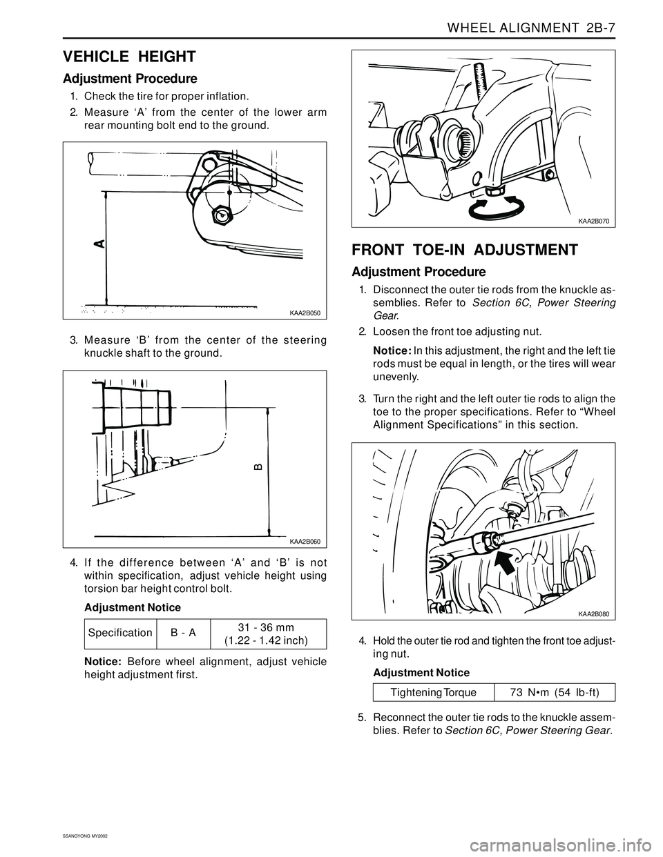
VEHICLE HEIGHT
Adjustment Procedure
1. Check the tire for proper inflation.
2. Measure ‘A’ from the center of the lower arm
rear mounting bolt end to the ground.
KAA2B050
3. Measure ‘B’ from the center of the steering
knuckle shaft to the ground.
KAA2B060
4. If the difference between ‘A’ and ‘B’ is not
within specification, adjust vehicle height using
torsion bar height control bolt.
Adjustment Notice
Specification31 - 36 mm
(1.22 - 1.42 inch)B - A
Notice: Before wheel alignment, adjust vehicle
height adjustment first.
KAA2B070
FRONT TOE-IN ADJUSTMENT
Adjustment Procedure
1. Disconnect the outer tie rods from the knuckle as-
semblies. Refer to Section 6C, Power Steering
Gear.
2. Loosen the front toe adjusting nut.
Notice: In this adjustment, the right and the left tie
rods must be equal in length, or the tires will wear
unevenly.
3. Turn the right and the left outer tie rods to align the
toe to the proper specifications. Refer to “Wheel
Alignment Specifications” in this section.
KAA2B080
4. Hold the outer tie rod and tighten the front toe adjust-
ing nut.
Adjustment Notice
Tightening Torque 73 Nm (54 lb-ft)
5. Reconnect the outer tie rods to the knuckle assem-
blies. Refer to Section 6C, Power Steering Gear.
Page 832 of 2053

SSANGYONG MY2002
2C-4 FRONT SUSPENSION
REPAIR INSTRUCTIONS
KAA2C020
ON-VEHICE SERVICE
FRONT HUB BEARING ASSEMBLY
Tools Required
DW340-050Sliding Hammer
DW340-060Front Hub Cap Remover/Installer
DW340-070Front Hub Flange Remover
661 589 01 07 00 Front Hub Adjusting Nut Remover/
nstaller
Removal and Installation Procedure
1. Raise and suitably support the vehicle.
2. Remove the front wheels. Refer to Section 2E,
Tires and Wheels.
3. Remove the caliper assembly. Refer to Section
4D, Front Disc Brakes.
4. Remove the hub cap with front hub cap remover/
Installer DW340-060 and sliding hammer DW340-
050.
KAA2C030
5. Remove the hub flange bolts.
Installation Notice
Tightening Torque 55 Nm (41 lb-ft)
6. Remove the snap ring and hub flange with front
hub flange remover DW340-070 and sliding
hammer DW340-050.
Notice:
When installing, coat the hub flange surface with
Loctitte.
Page 835 of 2053

FRONT SUSPENSION 2C-7
SSANGYONG MY2002
TORSION BAR
Removal and Installation Procedure
1. Raise and suitably support the vehicle.
2. Remove the height control bolt.
Notice:
Install the torsion bar and adjust the distance
be tween the end of the height control blot and
piece end of the bolt to be 50 - 55 mm (1.97 -
2.17 inch). Adjust the vehicle height.
KAA2C110
KAA2C120
KAA2C130
3. Remove the torsion bar fixing nuts and bolts and
then withdraw the torsion bar.
Installation Notice
Check and adjust the wheel alignment.
4. Installation should follow the removal procedure
in the reverse order.
LOWER CONTROL ARM
Tools Required
661 589 13 33 00 Ball Joint Remover
Removal and Installation Procedure
1. Raise and suitably support the vehicle.
2. Remove the front wheels. Refer to Section 2E,
Tires and Wheels.
3. Remove the torsion bar. Refer to “Torsion Bar” in
this section.
4. Remove the front shock absorber lower mounting
bolt and nut.
Installation Notice
Tightening Torque 70 Nm (52 lb-ft)
Tightening
TorqueM10
M1250 Nm (37 lb-ft)
70 Nm (52 lb-ft)
Page 836 of 2053

SSANGYONG MY2002
2C-8 FRONT SUSPENSION
5. Remove the stabilizer link-to-lower control arm nut.
Installation Notice
KAA2C100
KAA2C140
KAA2C150
KAA2C160
6. Remove the lower ball joint using the ball joint
remover 661 589 13 33 00.
Installation Notice
Tightening Torque 19 Nm (14 lb-ft)
7. Remove the lower control arm mounting bolts.
Installation Notice
UPPER CONTROL ARM
Tools Required
661589 13 33 00 BallJointRemover
Removal and Installation Procedure
1. Raise and suitably support the vehicle.
2. Remove the front wheels. Refer to Section 2E,
Tires and Wheels.
3. Remove the front shock absorber upper mounting nut.
Notice:
The distance between the nut end and the screw
end is 6 - 9 mm (0.24 - 0.35 inch).
Tightening Torque150 Nm (111 lb-ft)
Tightening Torque120 Nm (89 lb-ft)
The distance between the end of the nut and
the end of the stabilizer link should be 10 - 12
mm (0.39 - 0.47 inch) at the connection of the
stabilizer link and lower control arm.
8. Installation should follow the removal procedure
in the reverse order.
Page 837 of 2053

FRONT SUSPENSION 2C-9
SSANGYONG MY2002
4. Remove the upper ball joint using the ball joint
remover 661 589 13 33 00.
Installation Notice
KAA2C170
KAA2C180
KAA2C130
KAA2C160
5. Remove the fulcrum pin mounting bolts and nuts
and remove the upper control arm.
Removal Notice
Tightening Torque115 Nm (85 lb-ft)
FRONT SHOCK ABSORBER
Removal and Installation Procedure
1. Raise and suitably support the vehicle.
2. Remove the front wheels. Refer to Section 2E,
Tires and Wheels.
3. Remove the front shock absorber lower mounting
bolt and nut.
Removal Notice
4. Remove the front shock absorber upper mounting
nut.
Notice:
The distance between the nut end and the screw
end is 6 - 9 mm (0.24 - 0.35 inch).
5. Installation should follow the removal procedure
in the reverse order.
Tightening Torque130 Nm (96 lb-ft)
Tightening Torque 70 Nm (52 lb-ft)
Be careful not to damage or lose the adjusting
shims.
Check and adjust the wheel alignment.
6. Installation should follow the removal procedure
in the reverse order.
Page 838 of 2053

SSANGYONG MY2002
2C-10 FRONT SUSPENSION
LOWER BALL JOINT
Removal and Installation Procedure
1. Raise and suitably support the vehicle.
2. Remove the front wheels. Refer to Section 2E,
Tires and Wheels.
3. Remove the knuckle assembly. Refer to “Knuckle
Assembly” in this section.
4. Remove the lower ball joint.
Installation Notice
KAA2C190
KAA2C2005. Installation should follow the removal procedure
in the reverse order.
UPPER BALL JOINT
Removal and Installation Procedure
1. Raise and suitably support the vehicle.
2. Remove the front wheels. Refer to Section 2E,
Tires and Wheels.
3. Remove the knuckle assembly. Refer to “Knuckle
Assembly” in this section.
4. Remove the upper ball joint.
Installation Notice
5. Installation should follow the removal procedure
in the reverse order.
Tightening Torque 70 Nm (52 lb-ft)
Tightening Torque130 Nm (96 lb-ft)
Page 839 of 2053

FRONT SUSPENSION 2C-11
SSANGYONG MY2002
KNUCKLE ASSEMBLY
Tools Required
661589 13 33 00 BallJointRemover
Removal and Installation Procedure
1. Raise and suitably support the vehicle.
2. Remove the front wheels. Refer to Section 2E,
Tires and Wheels.
3. Remove the caliper assembly. Refer to Section
4D, Front Disc Brakes.
4. Remove the front hub bearing assembly. Refer to
“ Front hub bearing assembl y ” in this section.
KAA2C060
KAA2C210
KAA2C220
5. Remove the splash shield mounting bolts.
Installation Notice
6. Remove the front wheel speed sensor.
Installation Notice
KAA2C230
7. Remove the outer tie rod nuts and disconnect the
tie rod ends from the knuckle using the ball joint
remover 661 589 13 33 00.
Installation Notice
Tightening Torque 6 Nm (53 lb-in)
Tightening Torque 5 Nm (33 lb-in)
Tightening Torque 40 Nm (30 lb-ft)
Page 855 of 2053

SECTION 2E
TIRES AND WHEELS
TABLE OF CONTENTS
Description and Operation....................................2E-2
Tire and Wheel Balancing....................................2E-2
Tire Chain Usage.................................................2E-3
Replacement Tires...............................................2E-3
All Season Tires...................................................2E-3
Passenger Metric Sized Tires...............................2E-3
Tire Label............................................................2E-4
Spare Tire............................................................2E-4
Wheels................................................................2E-4
Inflation of Tires...................................................2E-4
Diagnostic Information and Procedures..............2E-5
Wheel Runout......................................................2E-5
Maintenance and Repair.....................................2E-6
On-Vehicle Service.................................................2E-6Wheel..................................................................2E-6
On-Vehicle Balancing ...........................................2E-7
Unit Repair............................................................2E-8
Alloy Wheel Porosity............................................2E-8
Alloy Wheel Refinishing .......................................2E-8
Off-Vehicle Balancing ..........................................2E-9
Correcting Non-Uniform Tires...............................2E-9
Tire and Wheel Match-Mounting...........................2E-9
Tire Mounting and Dismounting............................2E-9
Specifications.....................................................2E-10
Tire Size and Pressure Specifications.................2E-10
Inflation Pressure Conversion Specifications.......2E-10
Fastener Tightening Specifications.....................2E-10