tires SSANGYONG KORANDO 1997 Service Owner's Guide
[x] Cancel search | Manufacturer: SSANGYONG, Model Year: 1997, Model line: KORANDO, Model: SSANGYONG KORANDO 1997Pages: 2053, PDF Size: 88.33 MB
Page 1474 of 2053
SSANGYONG MY2002
6C-6 POWER STEERING GEAR
POWER STEERING RACK AND
PINION GEAR BENCH TESTING
Removal and Installation Procedure
Notice: Pressure checks or pressure and flow checks
may also be conducted using this setup.
1. Disconnect and remove the power steering gear.
Refer to “Rack and Pinion Assembly” in this
section.
2. Place the power steering gear on a bench next to
the vehicle.
3. Disconnect the pressure line at the point where the
hose connects to the pipe. Extend this line to reach
the power steering gear on the bench.
4. Disconnect the return line from the power steering
fluid reservoir. Extend this line to reach the power
steering gear on the bench.
5. Connect the power steering pipes to the power
steering gear.
6. Start the engine and allow it to idle for 10 seconds.
7. Check the power steering fluid level. Refer to
Section 6A, Power Steering System.
8. Start the engine and turn the rack and pinion stub
shaft a full turn in each direction. Hold the shaft
against each stop for 5 seconds.
9. Inspect for possible leak points. Refer to Section
6A, Power Steering System.
Installation Procedure
1. Stop the engine.
2. Disconnect the power steering pipes from the power
steering gear.
KAA6C020
3. Remove the extensions and reconnect the pressure
and return lines.
4. Install and connect the power steering gear. Refer
to “Rack and Pinion Assembly” in this section.
5. Start the engine and allow it to idle for 10 seconds.
6. Check the power steering fluid level. Refer to
Section 6A, Power Steering System.
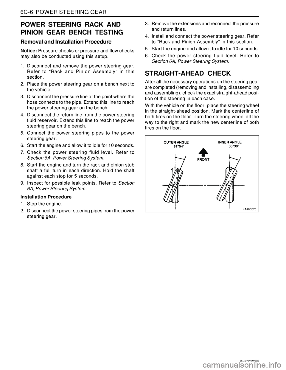
STRAIGHT-AHEAD CHECK
After all the necessary operations on the steering gear
are completed (removing and installing, disassembling
and assembling), check the exact straight-ahead posi-
tion of the steering in each case.
With the vehicle on the floor, place the steering wheel
in the straight-ahead position. Mark the centerline of
both tires on the floor. Turn the steering wheel all the
way to the right and mark the new centerline of both
tires on the floor.
Page 1476 of 2053

SSANGYONG MY2002
6C-8 POWER STEERING GEAR
KAA6C040
KAA6C030
ON-VEHICLE SERVICE
RACK AND PINION ASSEMBLY
Tools Required
661 589 13 33 00 Ball Joint Remover
Removal and Installation Procedure
1. Raise and suitably support the vehicle.
2. Remove the wheels. Refer to Section 2E, Tires
and Wheels.
3. Remove the intermediate shaft. Refer to
“Intermediate shaft” in this section.
4. Disconnect the return line pipe from the power
steering gear outlet. Place a drain pan under the
steering gear to catch the power steering fluid.
Installation Notice
REPAIR INSTRUCTIONS
Tightening Torque 17 Nm (13 lb-ft)
5. Disconnect the pressure line pipe from the power
steering gear inlet.
Installation Notice
Tightening Torque 17 Nm (13 lb-ft)
Page 1477 of 2053

POWER STEERING GEAR 6C-9
SSANGYONG MY2002
KAA6C140
KAA6C050
KAA6C050
6. Remove the outer tie rod nuts and disconnect the
tie rod ends from the knuckle using the ball joint
remover 661 589 13 33 00.
Installation Notice
7. Remove the rack and pinion assembly mounting
bolts and remove therackand pinion assembly.
Installation Notice
Tightening Torque 40 Nm (30 lb-ft)
After installing the rack and pinion assembly,
bleed the power steering system. Refer to
Section 6A, Power Steering System.
OUTER TIE ROD
Tools Required
661589 13 33 00 BallJointRemover
Removal and Installation Procedure
1. Remove the wheel. Refer to Section 2E, Tires and
wheels.
2. Mark the threads on the inner tie rod to aid in
repositioning the adjusting nut.
3. Remove the outer tie rod nut and disconnect the
outer tie rod from the knuckle using the ball joint
remover 661 589 13 33 00.
Installation Notice
Tightening Torque 78 Nm (58 lb-ft)
Tightening Torque 40 Nm (30 lb-ft)
Page 1478 of 2053

SSANGYONG MY2002
6C-10 POWER STEERING GEAR
KAA6C090
KAA6C100
KAA6C110
KAA6C080
4. Loosen the outer tie rod adjusting nut and remove
the outer tie rod by twisting it off the inner tie rod.
Installation Notice:
After Installation, perform a front toe adjustment.
Refer to Section 2B, Wheel Alignment.
DUST BOOT
Removal and Installation Procedure
1. Raise and suitably support the vehicle.
2. Remove the wheel. Refer to Section 2E, Tires and
wheels.
3. Remove the outer tie rod. Refer to “Outer Tie Rod”
in this section.
4. Remove the dust boot retaining clamps.
5. Remove the dust boot.
Installation Notice:
After Installation, perform a front toe adjustment.
Refer to Section 2B, Wheel Alignment.
INTERMEDIATE SHAFT
Removal and Installation Procedure
1. Turn the steering wheel until it is horizontal. This
is the straight-ahead position. Make a mark on
the stub shaft housing that lines up with a mark
on the intermediate shaft lower universal joint.
Installation Notice:
When attaching the lower universal joint, the
marks on the intermediate shaft and on the stub
shaft should line up