check engine SSANGYONG KORANDO 1997 Service Manual PDF
[x] Cancel search | Manufacturer: SSANGYONG, Model Year: 1997, Model line: KORANDO, Model: SSANGYONG KORANDO 1997Pages: 2053, PDF Size: 88.33 MB
Page 276 of 2053
1G1 -- 8 M162 ENGINE INTAKE & EXHAUST
D AEW OO M Y_2000
Removal & Installation Procedure
DUpper Intake Manifold
1. Disconnect the vacuum hose (8,9).
2. Loosen the clip (22).
3. Disconnect the resonance flap connector.
4. Remove the upper intake manifold (5) after unscrew-
ing the bolt (6).
Installation Notice
Tightening Torque
22.5 -- 27.5 NSm
(16.6 -- 20.3 lb-ft)
Notice:Check the gasket and replace it if necessary.
5. Installation should follow the removal procedure in
the reverse order.
DLower Intake Manifold
Preceding work : removal of upper intake manifold
1. Remove the hose of brake booster vacuum line and
idle speed connector.
2. Disconnect the hot water inlet pipe from the bottom of
lower intake manifold.
3. Unscrew the bolt (17) and remove the lower intake
manifold (16).
Installation Notice
Tightening Torque
22.5 -- 27.5 NSm
(16.6 -- 20.3 lb-ft)
4. Start the engine and check for leaks at each connec-
tion part.
Page 277 of 2053
M162 ENGINE INTAKE & EXHAUST 1G1 -- 9
D AEW OO M Y_2000
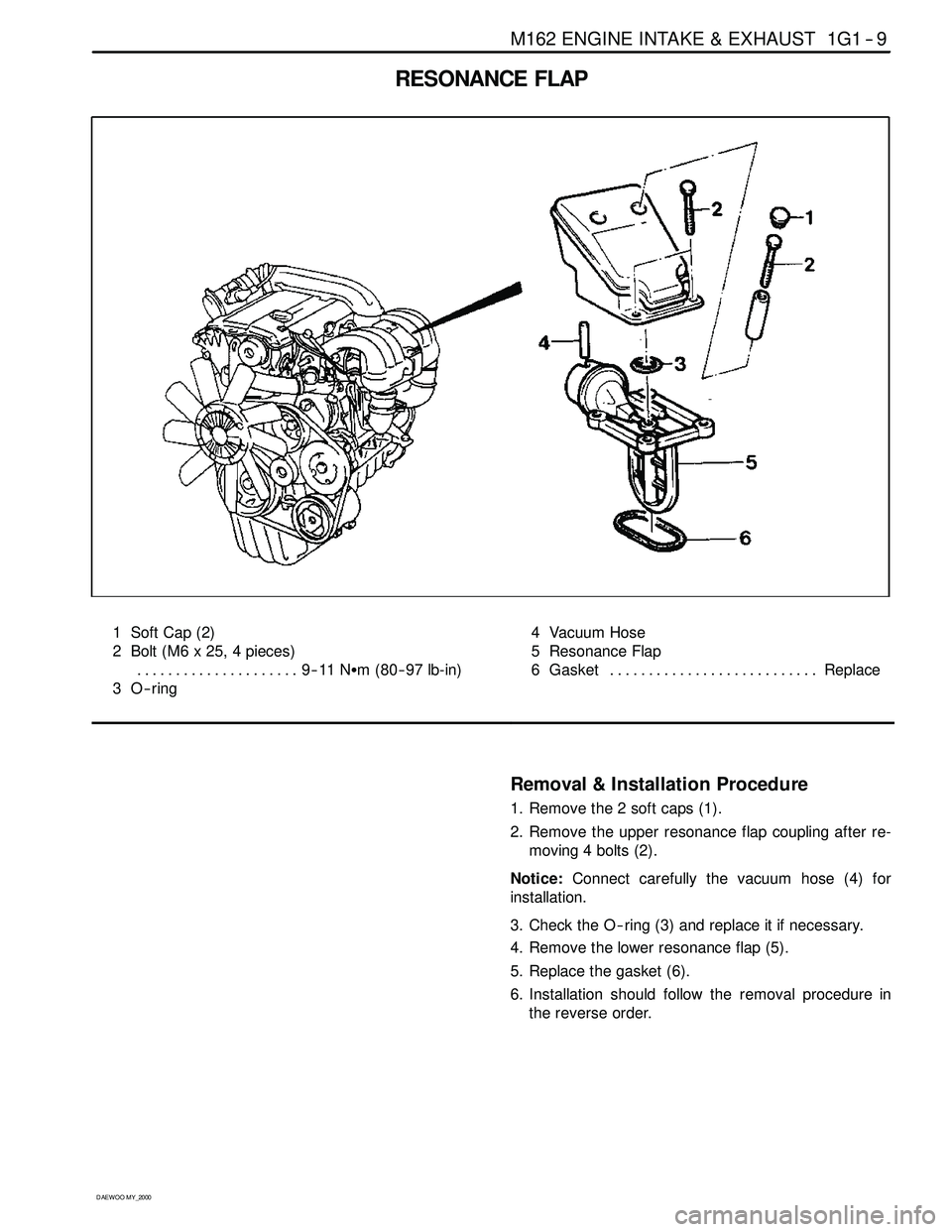
RESONANCE FLAP
1 Soft Cap (2)
2 Bolt (M6 x 25, 4 pieces)
9--11 NSm (80-- 97 lb-in) .....................
3O--ring4 Vacuum Hose
5 Resonance Flap
6 Gasket Replace...........................
Removal & Installation Procedure
1. Remove the 2 soft caps (1).
2. Remove the upper resonance flap coupling after re-
moving 4 bolts (2).
Notice:Connect carefully the vacuum hose (4) for
installation.
3. Check the O -- ring (3) and replace it if necessary.
4. Remove the lower resonance flap (5).
5. Replace the gasket (6).
6. Installation should follow the removal procedure in
the reverse order.
Page 280 of 2053
1G1 -- 12 M162 ENGINE INTAKE & EXHAUST
D AEW OO M Y_2000
Removal & Installation Procedure
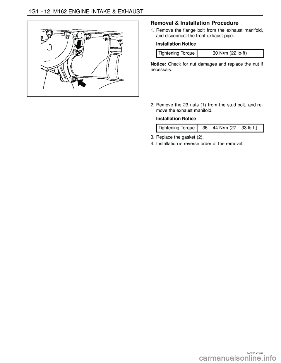
1. Remove the flange bolt from the exhaust manifold,
and disconnect the front exhaust pipe.
Installation Notice
Tightening Torque
30 NSm (22 lb-ft)
Notice:Check for nut damages and replace the nut if
necessary.
2. Remove the 23 nuts (1) from the stud bolt, and re-
move the exhaust manifold.
Installation Notice
Tightening Torque
36 -- 44 NSm (27 -- 33 lb-ft)
3. Replace the gasket (2).
4. Installation is reverse order of the removal.
Page 284 of 2053
1A2 -- 12 GENERAL ENGINE INFORMATION
D AEW OO M Y_2000
Leakage Test
1. Warm the engine up to normal operating tempera-
ture.
2. Disconnect the negative battery cable.
3. Remove the spark plugs.
4. Check the coolant level by opening the coolant
surge tank cap and replenish if insufficient.
5. Open the engine oil filler cap.
6. Connect the tester to air pressure line and adjust the
scale of tester.
7. Install the connecting hose to spark plug hole.
YAA1A2080
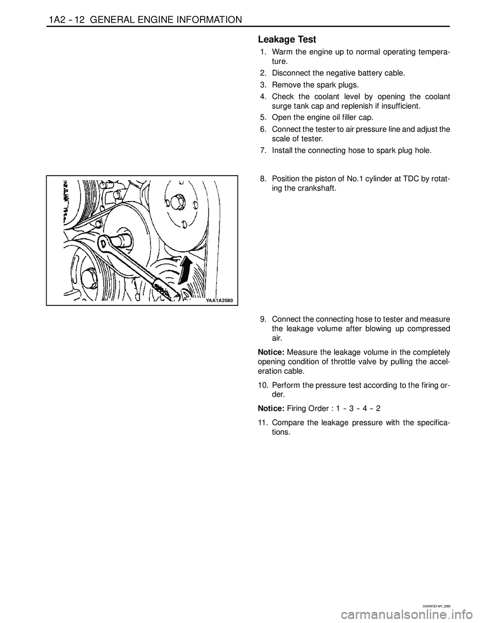
8. Position the piston of No.1 cylinder at TDC by rotat-
ing the crankshaft.
9. Connect the connecting hose to tester and measure
the leakage volume after blowing up compressed
air.
Notice:Measure the leakage volume in the completely
opening condition of throttle valve by pulling the accel-
eration cable.
10. Perform the pressure test according to the firing or-
der.
Notice:Firing Order : 1 -- 3 -- 4 -- 2
11. Compare the leakage pressure with the specifica-
tions.
Page 291 of 2053
GENERAL ENGINE INFORMATION 1A2 -- 7
D AEW OO M Y_2000
DIAGNOSIS
OIL LEAK DIAGNOSIS
Most fluid oil leaks are easily located and repaired by
visually finding the leak and replacing or repairing the
necessary parts. On some occasions a fluid leak may be
difficult to locate or repair. The following procedures may
help you in locating and repairing most leaks.
Finding the Leak
1. Identify the fluid. Determine whether it is engine oil,
automatic transmission fluid, power steering fluid,
etc.
2. Identify where the fluid is leaking from.
2.1 After running the vehicle at normal operating
temperature, park the vehicle over a large sheet
of paper.
2.2 Wait a few minutes.
2.3 You should be able to find the approximate loca-
tion of the leak by the drippings on the paper.
3. Visually check around the suspected component.
Check around all the gasket mating surfaces for
leaks. A mirror is useful for finding leaks in areas that
are hard to reach.
4. If the leak still cannot be found, it may be necessary
to clean the suspected area with a degreaser, steam
or spray solvent.
4.1 Clean the area well.
4.2 Dry the area.
4.3 Operate the vehicle for several miles at normal
operating temperature and varying speeds.
4.4 After operating the vehicle, visually check the
suspected component.
4.5 If you still cannot locate the leak, try using the
powder or black light and dye method.
Powder Method
1. Clean the suspected area.
2. Apply an aerosol-- type powder (such as foot powder)
to the suspected area.
3. Operate the vehicle under normal operating condi-
toins.
4. Visually inspect the suspected component. You
should be able to trace the leak path over the white
powder surface to the source.
Black Light and Dye Method
A dye and light kit is available for finding leaks, Refer to
the manufacturer ’s directions when using the kit.
1. Pour the specified amount of dye into the engine oil fill
tube.
2. Operate the vehicle normal operating conditions as
directed in the kit.
3. Direct the light toward the suspected area. The dyed
fluid willappear as a yellow path leading to the
source.
Repairing the Leak
Once the origin of the leak has been pinpointed and
traced back to its source, the cause of the leak must be
determined n order for it to be repaired properly. If a gas-
ket is replaced, but the sealing flange is bent, the new
gasket will not repair the leak. Thebent flange must be
repaired also. Before attempting to repair a leak, check
for the following conditions and correct them as they
may cause a leak.
Gaskets
DThe fluid level/pressure is too high.
DThe crankcase ventilation system is malfunctioning.
DThe fasteners are tightened improperly or the threads
are dirty or damaged.
DThe flanges or the sealing surface is warped.
DThere are scratches, burrs or other damage to the
sealing surface.
DThe gasket is damaged or worn.
DThere is cracking or porosity of the component.
DAn improper seal was used (where applicable).
Seals
DThe fluid level/pressure is too high.
DThe crankcase ventilation system is malfunctioning.
DThe seal bore is damaged (scratched, burred or
nicked).
DThe seal is damaged or worn.
DImproper installation is evident.
DThere are cracks in the components.
DThe shaft surface is scratched, nicked or damaged.
DA loose or worn bearing is causing excess seal wear.
Page 313 of 2053
1B2 -- 20 M161 ENGINE MECHANICAL
D AEW OO M Y_2000
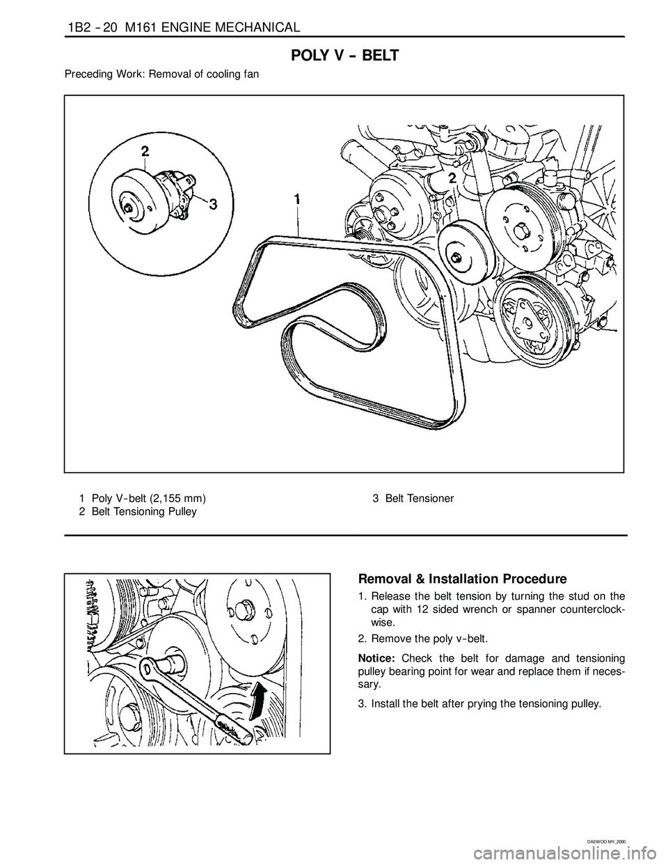
POLY V -- BELT
Preceding Work: Removal of cooling fan
1 Poly V-- belt (2,155 mm)
2 Belt Tensioning Pulley3 Belt Tensioner
Removal & Installation Procedure
1. Release the belt tension by turning the stud on the
cap with 12 sided wrench or spanner counterclock-
wise.
2. Remove the poly v -- belt.
Notice:Check the belt for damage and tensioning
pulley bearing point for wear and replace them if neces-
sary.
3. Install the belt after prying the tensioning pulley.
Page 317 of 2053
1B2 -- 24 M161 ENGINE MECHANICAL
D AEW OO M Y_2000
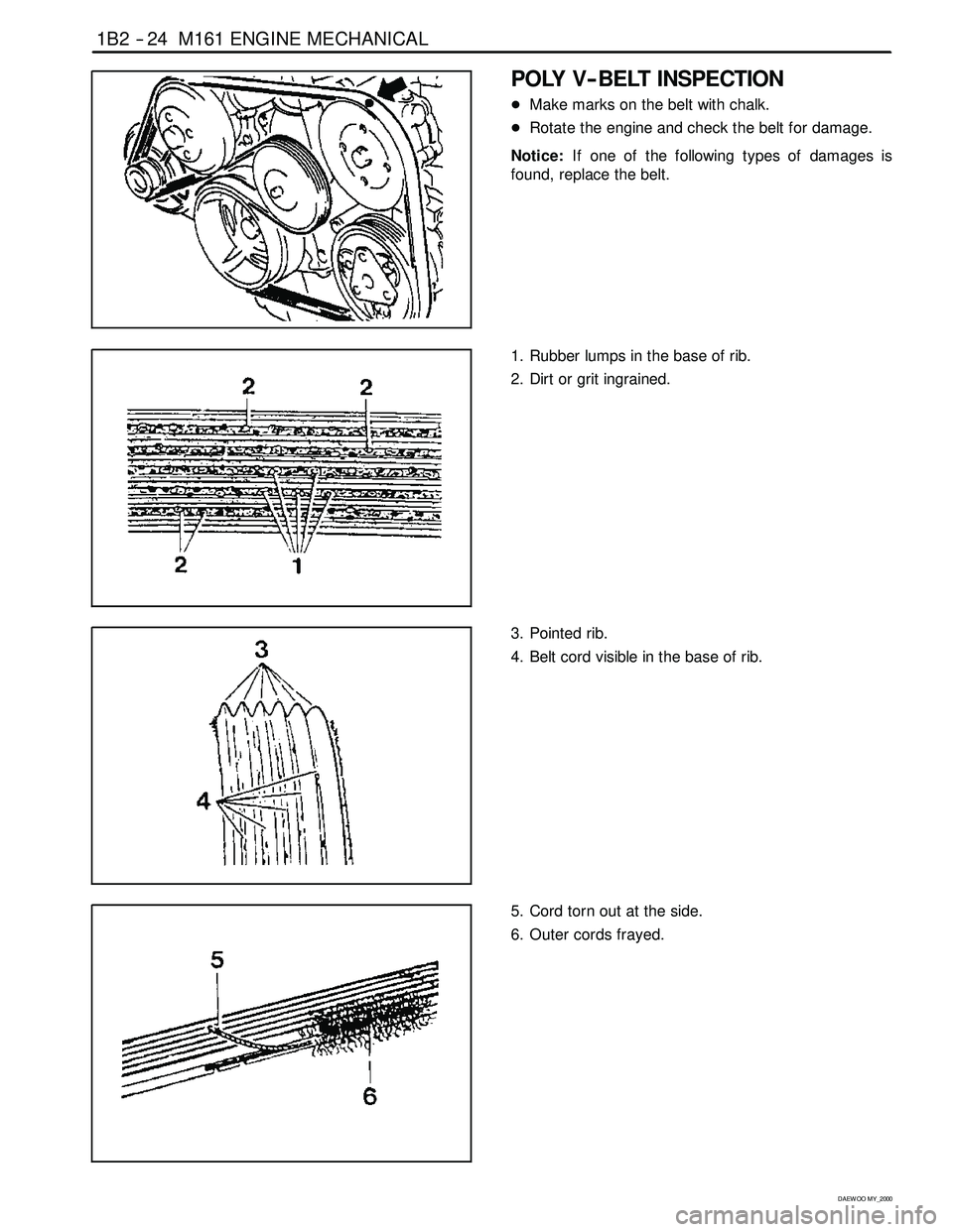
POLY V-- BELT INSPECTION
DMake marks on the belt with chalk.
DRotate the engine and check the belt for damage.
Notice:If one of the following types of damages is
found, replace the belt.
1. Rubber lumps in the base of rib.
2. Dirt or grit ingrained.
3. Pointed rib.
4. Belt cord visible in the base of rib.
5. Cord torn out at the side.
6. Outer cords frayed.
Page 320 of 2053
M161 ENGINE MECHANICAL 1B2 -- 27
D AEW OO M Y_2000
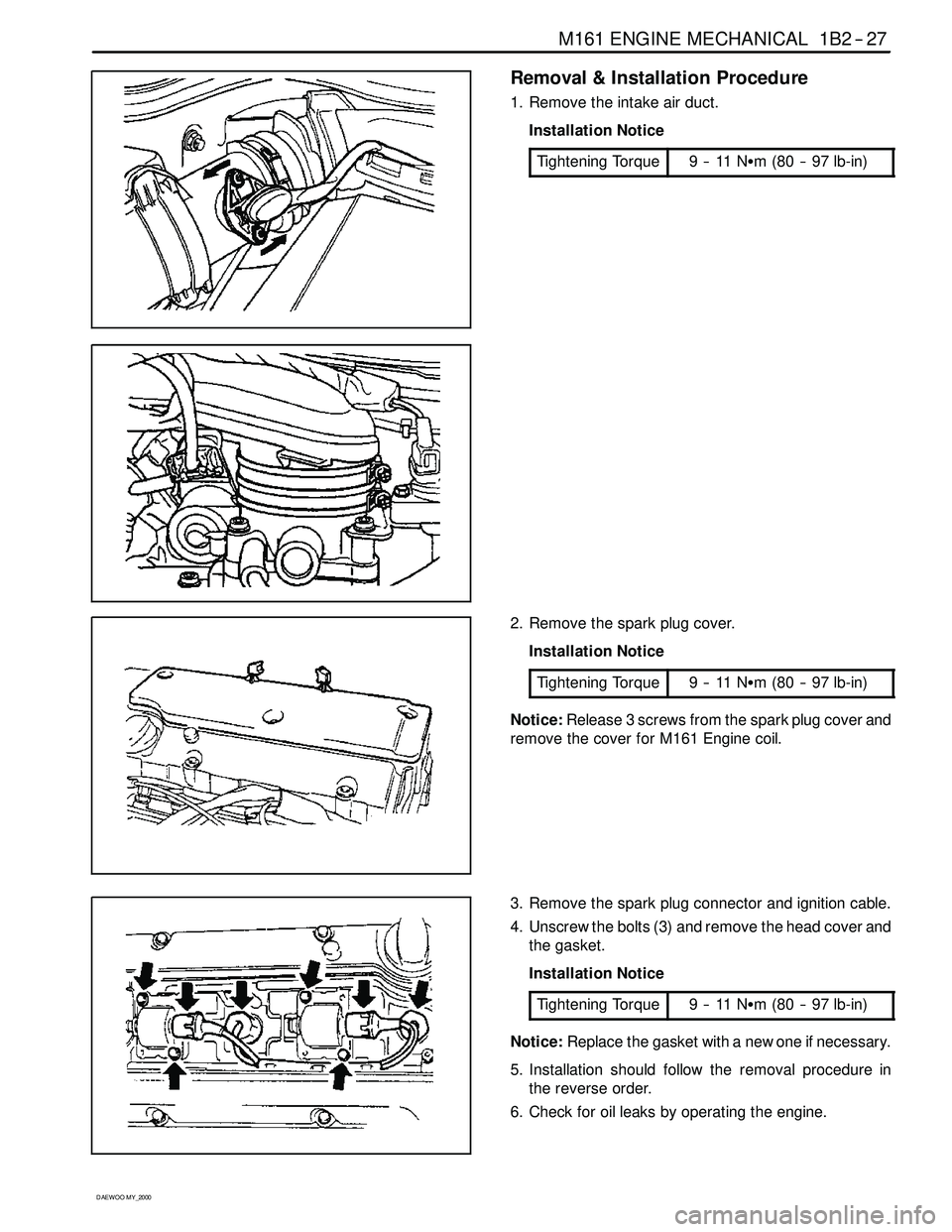
Removal & Installation Procedure
1. Remove the intake air duct.
Installation Notice
Tightening Torque
9--11NSm (80 -- 97 lb-in)
2. Remove the spark plug cover.
Installation Notice
Tightening Torque
9--11NSm (80 -- 97 lb-in)
Notice:Release 3 screws from the spark plug cover and
remove the cover for M161 Engine coil.
3. Remove the spark plug connector and ignition cable.
4. Unscrew the bolts (3) and remove the head cover and
the gasket.
Installation Notice
Tightening Torque
9--11NSm (80 -- 97 lb-in)
Notice:Replace the gasket with a new one if necessary.
5. Installation should follow the removal procedure in
the reverse order.
6. Check for oil leaks by operating the engine.
Page 326 of 2053
M161 ENGINE MECHANICAL 1B2 -- 33
D AEW OO M Y_2000
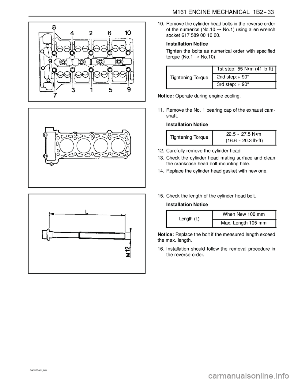
10. Remove the cylinder head bolts in the reverse order
of the numerics (No.10→No.1) using allen wrench
socket617589001000.
Installation Notice
Tighten the bolts as numerical order with specified
torque (No.1→No.10).
1st step: 55 NSm (41 lb-ft)
Tightening Torque2nd step: + 90°ggq
3rd step: + 90°
Notice:Operate during engine cooling.
11. Remove the No. 1 bearing cap of the exhaust cam-
shaft.
Installation Notice
Tightening Torque
22.5 -- 27.5 NSm
(16.6 -- 20.3 lb-ft)
12. Carefully remove the cylinder head.
13. Check the cylinder head mating surface and clean
the crankcase head bolt mounting hole.
14. Replace the cylinder head gasket with new one.
15. Check the length of the cylinder head bolt.
Installation Notice
Length(L)When New 100 mmLength(L)Max. Length 105 mm
Notice:Replace the bolt if the measured length exceed
the max. length.
16. Installation should follow the removal procedure in
the reverse order.
Page 329 of 2053
1B2 -- 36 M161 ENGINE MECHANICAL
D AEW OO M Y_2000
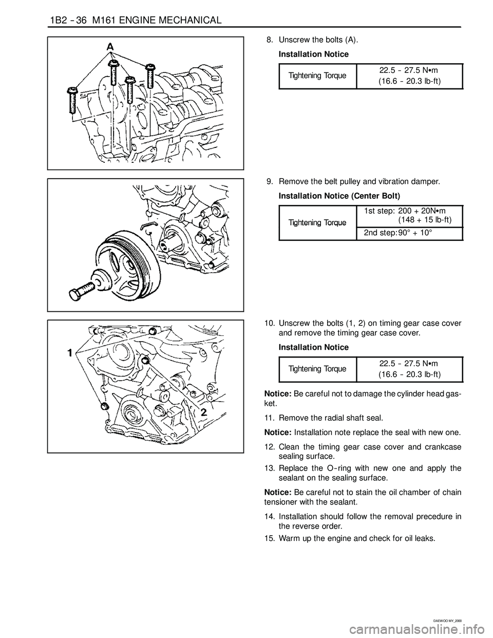
8. Unscrew the bolts (A).
Installation Notice
Tightening Torque
22.5 -- 27.5 NSm
(16.6 -- 20.3 lb-ft)
9. Remove the belt pulley and vibration damper.
Installation Notice (Center Bolt)
Ti
ghteningTo rque
1st step: 200 + 20NSm
(148 + 15 lb-ft)
TighteningTorque
2nd step: 90°+10°
10. Unscrew the bolts (1, 2) on timing gear case cover
and remove the timing gear case cover.
Installation Notice
Tightening Torque
22.5 -- 27.5 NSm
(16.6 -- 20.3 lb-ft)
Notice:Be careful not to damage the cylinder head gas-
ket.
11. Remove the radial shaft seal.
Notice:Installation note replace the seal with new one.
12. Clean the timing gear case cover and crankcase
sealing surface.
13. Replace the O -- ring with new one and apply the
sealant on the sealing surface.
Notice:Be careful not to stain the oil chamber of chain
tensioner with the sealant.
14. Installation should follow the removal precedure in
the reverse order.
15. Warm up the engine and check for oil leaks.