engine SSANGYONG KORANDO 1997 Service Repair Manual
[x] Cancel search | Manufacturer: SSANGYONG, Model Year: 1997, Model line: KORANDO, Model: SSANGYONG KORANDO 1997Pages: 2053, PDF Size: 88.33 MB
Page 500 of 2053

1F2 -- 82 M161 ENGINE CONTROLS
D AEW OO M Y_2000
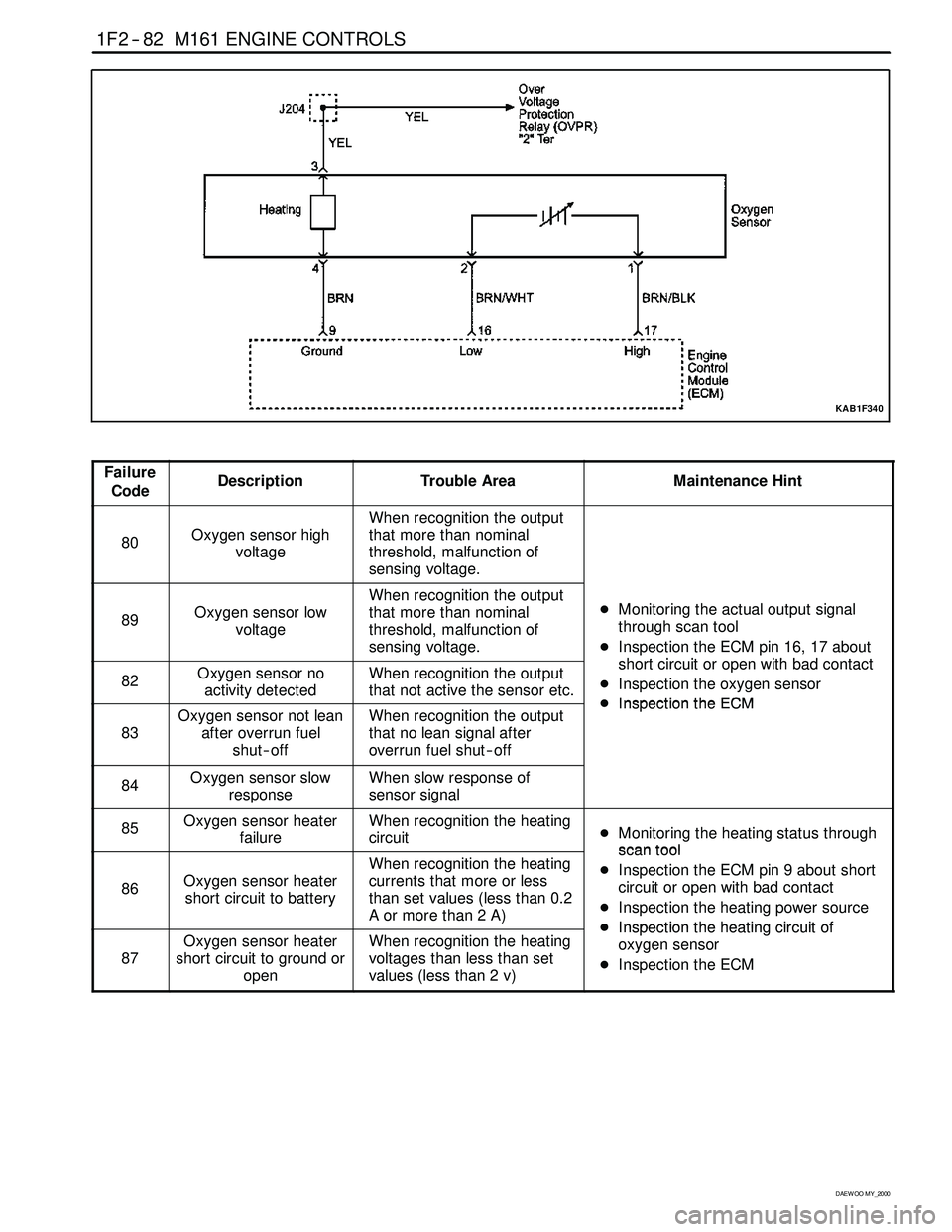
KAB1F340
Failure
CodeDescriptionTrouble AreaMaintenance Hint
80Oxygen sensor high
voltage
When recognition the output
that more than nominal
threshold, malfunction of
sensing voltage.
89Oxygen sensor low
voltage
When recognition the output
that more than nominal
threshold, malfunction of
sensing voltage.DMonitoring the actual output signal
through scan tool
DInspection the ECM pin 16, 17 about
htiitithbdtt
82Oxygen sensor no
activity detectedWhen recognition the output
that not active the sensor etc.short circuit or open with bad contact
DInspection the oxygen sensor
DInspectiontheECM
83
Oxygen sensor not lean
after overrun fuel
shut -- offWhen recognition the output
that no lean signal after
overrun fuel shut -- offDInspectiontheECM
84Oxygen sensor slow
responseWhen slow response of
sensor signal
85Oxygen sensor heater
failureWhen recognition the heating
circuitDMonitoring the heating status through
scantool
86Oxygen sensor heater
short circuit to battery
When recognition the heating
currents that more or less
than set values (less than 0.2
Aormorethan2A)scantool
DInspection the ECM pin 9 about short
circuit or open with bad contact
DInspection the heating power source
DInspectiontheheatingcircuitof
87
Oxygen sensor heater
short circuit to ground or
openWhen recognition the heating
voltages than less than set
values (less than 2 v)DInspectiontheheating circuitof
oxygen sensor
DInspection the ECM
Page 501 of 2053

M161 ENGINE CONTROLS 1F2 -- 83
D AEW OO M Y_2000
Failure
CodeDescriptionTrouble AreaMaintenance Hint
81
Bank 1 system short
term fuel trim adaptation
below lean threshold
When recognition the value
less than nominal control
threshold, it means that when
big deviation in control range
of adaptation values through
fuel and air mixture formation
93
Bank 1 system short
term fuel trim adaptation
above rich threshold
When recognition the value
more than nominal control
threshold, it means that when
big deviation in control range
of adaptation values through
fuel and air mixture formation
96
Bank 1 system short
term fuel trim at rich
stopWhen recognition the short
term fuel trim that more than
nominal threshold
97
Bank1 system short
term fuel trim at lean
stopWhen recognition the short
term fuel trim that less than
nominal threshold
DInspection the intake air leakage
DIns
pection the injectionquantities with
98
Bank 1 system idle
adaptation failure (above
rich threshold)When recognition the long
term fuel trim exceeds rich
threshold
DInspectiontheinjectionquantitieswith
injector block or leakage
DInspection the exhaust leakage
DInspection the ECM
99
Bank 1 system idle
adaptation failure (below
rich threshold)When recognition the long
term fuel trim exceeds lean
threshold
p
100
Bank 1 system learning
control failure (rich, low
load)When recognition the long
term fuel trim exceeds rich
threshold
101
Bank 1 system learning
control failure (lean, low
load)When recognition the long
term fuel trim exceeds lean
threshold
102
Bank 1 system learning
control failure (rich, high
load)When recognition the long
term fuel trim exceeds rich
threshold
103
Bank 1 system learning
control failure (rich, low
load)When recognition the long
term fuel trim exceeds lean
threshold
Circuit Description
In order to control emissions, a catalytic converter is used to covert harmful emissions into harmless water vapor and
carbon dioxide. The ECM has the ability to monitor this process by using a oxygen sensor. The oxygen sensor pro-
duces and output signal which indicates the storage capacity of the catalyst. This in turn indicates the catalyst’s ability
to convert exhaust emission effectively. If the oxygen sensor pigtail wiring, connector, or terminal is damaged. Do not
attempt to repair the wiring, connector, or terminals. In order for the sensor to function properly, it must have a clean air
reference provided to it. This clean air reference is obtained by way of the oxygen sensor wire(s). Any attempt to repair
the wires, connector, or terminal and degrade the oxygen sensor performance.
Page 502 of 2053

1F2 -- 84 M161 ENGINE CONTROLS
D AEW OO M Y_2000
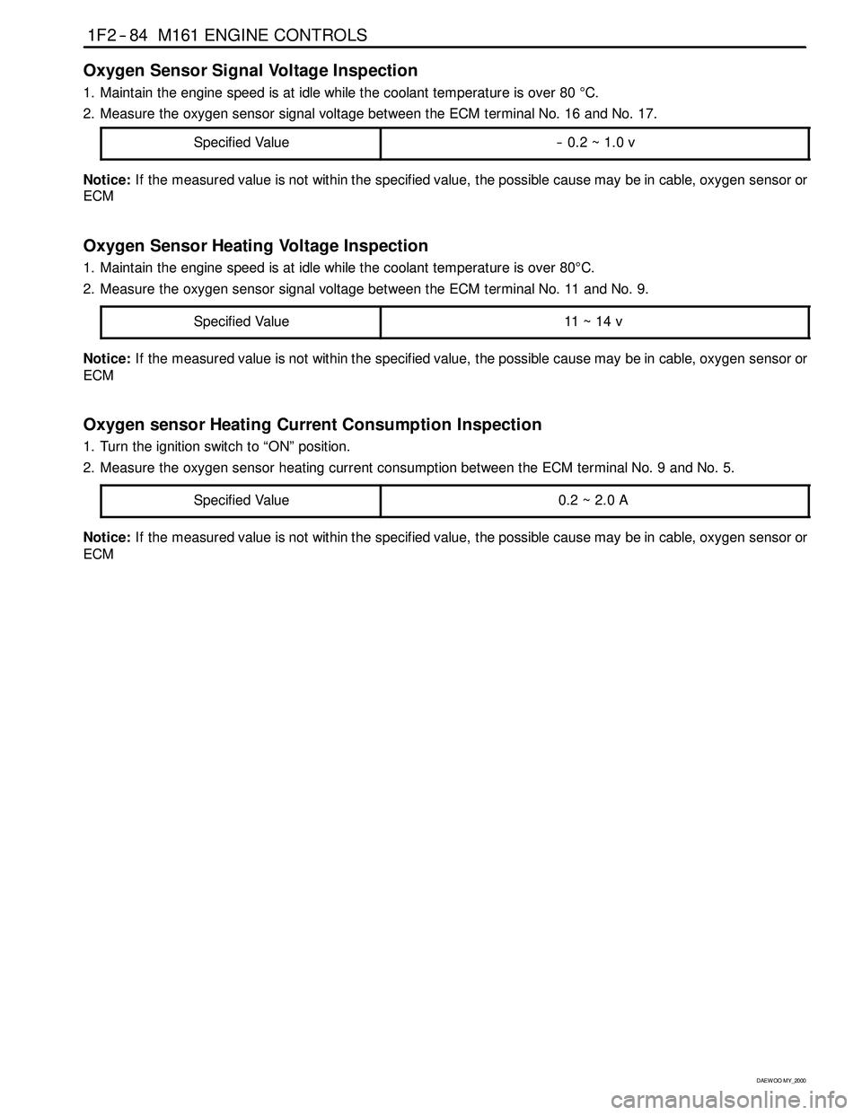
Oxygen Sensor Signal Voltage Inspection
1. Maintain the engine speed is at idle while the coolant temperature is over 80°C.
2. Measure the oxygen sensor signal voltage between the ECM terminal No. 16 and No. 17.
Specified Value
-- 0.2 ~ 1.0 v
Notice:If the measured value is not within the specified value, the possible cause may be in cable, oxygen sensor or
ECM
Oxygen Sensor Heating Voltage Inspection
1. Maintain the engine speed is at idle while the coolant temperature is over 80°C.
2. Measure the oxygen sensor signal voltage between the ECM terminal No. 11 and No. 9.
Specified Value
11 ~ 14 v
Notice:If the measured value is not within the specified value, the possible cause may be in cable, oxygen sensor or
ECM
Oxygen sensor Heating Current Consumption Inspection
1. Turn the ignition switch to “ON” position.
2. Measure the oxygen sensor heating current consumption between the ECM terminal No. 9 and No. 5.
Specified Value
0.2~2.0A
Notice:If the measured value is not within the specified value, the possible cause may be in cable, oxygen sensor or
ECM
Page 503 of 2053

M161 ENGINE CONTROLS 1F2 -- 85
D AEW OO M Y_2000
BLANK
Page 504 of 2053

1F2 -- 86 M161 ENGINE CONTROLS
D AEW OO M Y_2000
ENGINE CONTROL MODULE
YAA1F830
The Engine Control Module (ECM), located inside the right side kick panel, is the control center of the fuel injection
system. It constantly looks at the information from various sensors and controls the systems that affect the vehicle’s
performance. Engine rpm and air mass are used to measure the air intake quantity resulting in fuel injection metering.
The ECM also performs the diagnostic functions of the system. It can recognize operational problems, store failure
code(s) which identify the problem areas to aid the technician in making repairs.
There are no serviceable parts in the ECM. The calibrations are stored in the ECM in the Programmable Read Only
Memory (PROM).
The ECM supplies either 5 or 12 volts to power the sensors or switches. This is done through resistance in the ECM
which are so high in value that a test light will not come ON when connected to the circuit. In some cases, even an
ordinary shop voltmeter will not give and accurate reading because its resistance is too low. You must use a digital
voltmeter with a 10 Mohm input impedance to get accurate voltage readings. The ECM controls output circuits such as
the ignition coils, the fuel injectors, the fuel pump relay, the camshaft actuator, the canister purge valve, etc., by con-
trolling the ground circuit.
Page 505 of 2053

M161 ENGINE CONTROLS 1F2 -- 87
D AEW OO M Y_2000
BLANK
Page 506 of 2053

1F2 -- 88 M161 ENGINE CONTROLS
D AEW OO M Y_2000
SERIAL DATA COMMUNICATION
KAB1F350
Failure
CodeDescriptionTrouble AreaMaintenance Hint
23CAN communication
failure: ASR/MSR
When CAN signal message
missing or implausibility for
ASR/MSR unit or not
initialized condition
DInspection the ASR unit with CAN
connection
DInspection the Engine Control Module
(ECM) pin 38, 37 about short circuit or
open with bad contact
DInspection the ECM
24CAN communication
failure: ABS
When CAN signal message
missing or implausibility for
ABS unit or not initialized
conditionDInspection the ABS unit with CAN
connection
DInspection the ECM pin 38, 37 about
short circuit or open with bad contact
DInspection the ECM
26CAN communication
failure: TCU (A/T only)
When CAN signal message
missing or implausibility for
TCU unit or not initialized
conditionDInspection the TCM unit with CAN
connection
DInspection the ECM pin 38, 37 about
short circuit or open with bad contact
DInspection the ECM
Page 507 of 2053

M161 ENGINE CONTROLS 1F2 -- 89
D AEW OO M Y_2000
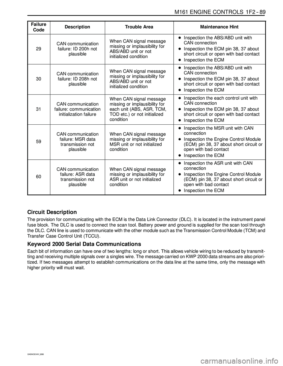
Failure
CodeDescriptionTrouble AreaMaintenance Hint
29
CAN communication
failure: ID 200h not
plausibleWhen CAN signal message
missing or implausibility for
ABS/ABD unit or not
initialized conditionDInspection the ABS/ABD unit with
CAN connection
DInspection the ECM pin 38, 37 about
short circuit or open with bad contact
DInspection the ECM
30
CAN communication
failure: ID 208h not
plausibleWhen CAN signal message
missing or implausibility for
ABS/ABD unit or not
initialized conditionDInspection the ABS/ABD unit with
CAN connection
DInspection the ECM pin 38, 37 about
short circuit or open with bad contact
DInspection the ECM
31
CAN communication
failure: communication
initialization failure
When CAN signal message
missing or implausibility for
each unit (ABS, ASR, TCM,
TOD etc.) or not initialized
conditionDInspection the each control unit with
CAN connection
DInspection the ECM pin 38, 37 about
short circuit or open with bad contact
DInspection the ECM
59
CAN communication
failure: MSR data
transmission not
plausibleWhen CAN signal message
missing or implausibility for
MSR unit or not initialized
condition
DInspection the MSR unit with CAN
connection
DInspection the Engine Control Module
(ECM) pin 38, 37 about short circuit or
open with bad contact
DInspection the ECM
60
CAN communication
failure: ASR data
transmission not
plausibleWhen CAN signal message
missing or implausibility for
ASR unit or not initialized
condition
DInspection the ASR unit with CAN
connection
DInspection the Engine Control Module
(ECM) pin 38, 37 about short circuit or
open with bad contact
DInspection the ECM
Circuit Description
The provision for communicating with the ECM is the Data Link Connector (DLC). It is located in the instrument panel
fuse block. The DLC is used to connect the scan tool. Battery power and ground is supplied for the scan tool through
the DLC. CAN line is used to communicate with the other module such as the Transmission Control Module (TCM) and
Transfer Case Control Unit (TCCU).
Keyword 2000 Serial Data Communications
Each bit of information can have one of two lengths: long or short. This allows vehicle wiring to be reduced by transmit-
ting and receiving multiple signals over a singles wire. The message carried on KWP 2000 data streams are also priori-
tized. If two messages attempt to establish communications on the data line at the same time, only the message with
higher prioritywill must wait.
Page 508 of 2053

1F2 -- 90 M161 ENGINE CONTROLS
D AEW OO M Y_2000
INTERNAL FAILURE
Failure
CodeDescriptionTrouble AreaMaintenance Hint
21Transmission coding
failureWhen faulty of variant coding
of transmission
DInspection the coding condition
through scan tool
DInspection the Engine Control Module
(ECM)
DInspection the CAN line
DInspection the TCM
136ECM failure (RAM)
When malfunction of random
access memory -- ECM
internal error
DInspection the ECM
142Uncoded/ unprogramed
ECMWhen malfunction of ECM
coding-- required ECM
encoding
DFulfill the ECM variant coding
137ECM failure (EPROM)
143
ECM failure
(EEPROM/Flash -- EPPOM
checksum failure)
144ECM failure (coding ID
checksum failure)When malfunction of ECM
internalDInspection the ECM
145ECM failure (coding
checksum failure)
146ECM failure (programming
checksum failure)
Page 509 of 2053

M161 ENGINE CONTROLS 1F2 -- 91
D AEW OO M Y_2000
BLANK