ABS SSANGYONG KORANDO 1997 Service Workshop Manual
[x] Cancel search | Manufacturer: SSANGYONG, Model Year: 1997, Model line: KORANDO, Model: SSANGYONG KORANDO 1997Pages: 2053, PDF Size: 88.33 MB
Page 994 of 2053

ABS AND TCS 4F-11
SSANGYONG MY2002
1 Master Cylinder
2 Hydraulic Modulator
3 Damper
4 Pump
5 Pump Motor
6 Accumulator
7 Inlet Valve for Each Wheel
ABS/TCS 5.3
Pressure Increased
KAA4F070
8 Outlet Valve for Each Wheel
9 Wheel
10 Prime Valve
11 Pilot Valve
12 Check Valve
13 ISD (Integrated Suction Damper)
Page 995 of 2053

SSANGYONG MY2002
4F-12 ABS AND TCS
Pressure Maintained
1 Master Cylinder
2 Hydraulic Modulator
3 Damper
4 Pump
5 Pump Motor
6 Accumulator
7 Inlet Valve for Each Wheel
KAA4F080
8 Outlet Valve for Each Wheel
9 Wheel
10 Prime Valve
11 Pilot Valve
12 Check Valve
13 ISD (Integrated Suction Damper)
Page 996 of 2053

ABS AND TCS 4F-13
SSANGYONG MY2002
Pressure Decreased
1 Master Cylinder
2 Hydraulic Modulator
3 Damper
4 Pump
5 Pump Motor
6 Accumulator
7 Inlet Valve for Each Wheel
KAA4F090
8 Outlet Valve for Each Wheel
9 Wheel
10 Prime Valve
11 Pilot Valve
12 Check Valve
13 ISD (Integrated Suction Damper)
Page 997 of 2053

SSANGYONG MY2002
4F-14 ABS AND TCS
COMPONENT LOCATOR
ABS, ABS/TCS 5.3
1 ABS/TCS Hydraulic Unit
(with EBCM in case of ABS only)
2 ABS/TCS EBCM Unit (in case of TCS)
3 Rear Wheel Speed Sensor
KAA4F100
4 ABS Warning Indicator Light
5 Diagnosis Connector
6 Front Wheel Speed Sensor
7 Acceleration Sensor
Page 998 of 2053
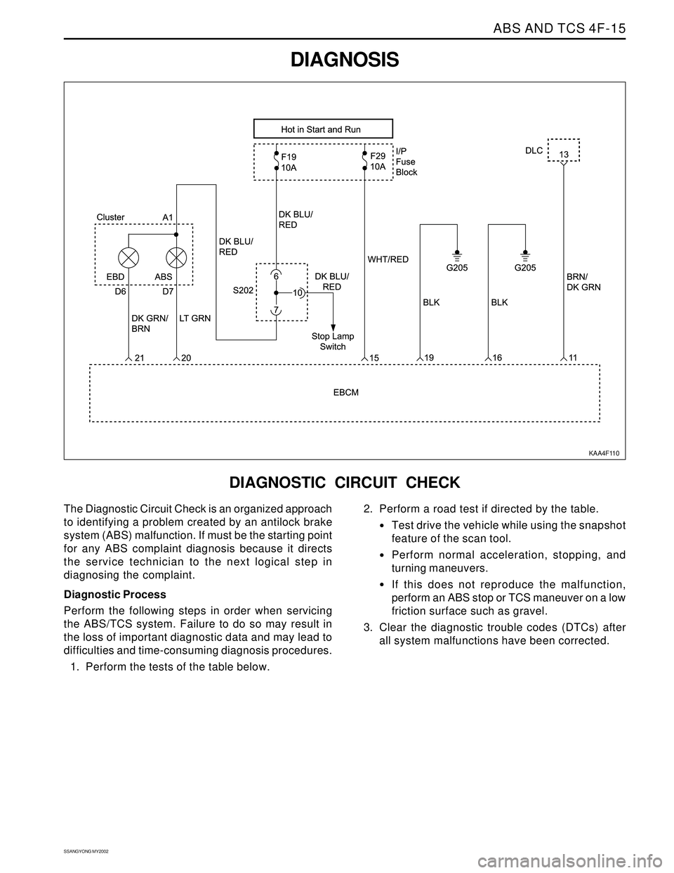
ABS AND TCS 4F-15
SSANGYONG MY2002
DIAGNOSIS
KAA4F110
DIAGNOSTIC CIRCUIT CHECK
The Diagnostic Circuit Check is an organized approach
to identifying a problem created by an antilock brake
system (ABS) malfunction. If must be the starting point
for any ABS complaint diagnosis because it directs
the service technician to the next logical step in
diagnosing the complaint.
Diagnostic Process
Perform the following steps in order when servicing
the ABS/TCS system. Failure to do so may result in
the loss of important diagnostic data and may lead to
difficulties and time-consuming diagnosis procedures.
1. Perform the tests of the table below.2. Perform a road test if directed by the table.
Test drive the vehicle while using the snapshot
feature of the scan tool.
Perform normal acceleration, stopping, and
turning maneuvers.
If this does not reproduce the malfunction,
perform an ABS stop or TCS maneuver on a low
friction surface such as gravel.
3. Clear the diagnostic trouble codes (DTCs) after
all system malfunctions have been corrected.
Page 999 of 2053

SSANGYONG MY2002
4F-16 ABS AND TCS
1. Install the scan tool.
2. Turn ignition switch to ON.
3. Select the Data List mode.
Is the scan tool receiving data from the electronic
brake control module (EBCM)?
Check the display.
Are there any current DTCs displayed?
1. Turn the ignition to LOCK for 10 seconds.
2. Turn the ignition to ON and observe the ABS
indicator.
Does the indicator light for 2 seconds and then go off?
Check the ABS indicator.
Did the ABS indicator turn on and stay on?
Check whether the vehicle is equipped with traction
control.
Is the vehicle equipped with traction control?
1. Turn the ignition to LOCK for 10 seconds.
2. Turn the ignition to ON and observe the TCS
indicator.
Does the indicator light for 2 seconds and then go off?
1. Turn the ignition to LOCK.
2. Disconnect the EBCM harness connector.
3. Turn the ignition to ON.
4. Use a digital voltmeter (DVM) to measure the
voltage from ground to terminal 1 and 50 of the
EBCM harness connector.
Is the voltage equal to the specified value?
1. Turn the ignition to LOCK.
2. Use a DVM to measure the resistance from the EBCM
harness connector, terminals 28 and 29 to ground.
Is the resistance equal to the specified value?
Repair the open in the circuit that failed.
Is the repair complete?
Use a DVM to measure the resistance between
terminal 46 of the EBCM harness connector and
terminal 8 of the data link connector (DLC).
Is the resistance below the specified value?
Replace the ABS unit.
Is the repair complete?
Repair the open or high resistance in circuit BrG
between terminal 11 of the EBCM harness connector
and terminal 13 of the DLC.
Is the repair complete?
Perform the road test described above.
Are any DTCs set? Step
1
2
3
4
5
6
7
8
9
10
11
12
13
Diagnostic Circuit Check
Action Yes
Go to Step 2
Refer to the
applicable DTC
table
Go to Step 5
Go to “ABS
Indicator Lamp
Illuminated
Constantly”
Go to Step 6
Go to Step 13
Go to Step 8
Go to Step 10
System OK
Go to Step 11
System OK
Go to Step 1
Go to the table
for the DTCNo
Go to Step 7
Go to Step 3
Go to Step 4
Go to
“ABS Indicator
Lamp Inopera-
tive
Go to Step 13
Go to “Traction
Control System
Indicator Lamp
Inoperative”
Go to “Power
Supply to
Control Mod-
ule, No DTCs
Stored
Go to Step 9
-
Go to Step 12
-
-
System OK Value(s)
-
-
-
-
-
-
11 - 14 v
≈ 0 Ω
-
2 Ω
-
-
-
Page 1000 of 2053

ABS AND TCS 4F-17
SSANGYONG MY2002
BLANK
Page 1001 of 2053

SSANGYONG MY2002
4F-18 ABS AND TCS
ABS INDICATOR LAMP INOPERATIVE
KAA4F120
Circuit Description
Battery voltage is supplied to the ABS warning lamp
with the ignition switch in the ON or START positions.
The warning lamp can be activated only by the ABS
control module internally supplying ground to terminal
20 or by the shorting bar in the ABS module connector
if the connector is disconnected from the module.
Diagnosis
This procedure checks for a problem in the wiring, a
faulty ground, a voltage supply problem, a burned out
indicator lamp, or a contact problem in a connector.
Cause(s)
A fuse has blown.
The indicator lamp has burned out.
There is a corroded or broken connector terminal.
There is a faulty ground connection.
There is a broken wire in a wiring harness.
The EBCM is faulty.Test Description
The number(s) below refer to step(s) on the diagnostic
table.
1. This test checks for any DTCs that may cause
the ABS indicator lamp to be inoperative.
2. This test verifies an inoperative lamp condition.
3. This test checks for voltage on the lamp circuit.
4. This begins a series of tests of the circuit from
the indicator lamp to the EBCM and ground.
19. This begins a series of tests of the voltage supply
circuits that power the indicator lamp.
Page 1002 of 2053

ABS AND TCS 4F-19
SSANGYONG MY2002
Step
1
2
3
4
5
6
7
8
9
10
11
12
13
ABS Indicator Lamp Inoperative
Action Yes
Go to the chart
for the DTC
Go to
“Intermittents
and Poo Con-
nections”
Go to Step 4
Go to Step 5
Go to Step 6
System OK
System OK
Go to Step 10
System OK
Go to Step 11
System OK
Go to Step 14
System OKNo
Go to Step 2
Go to Step 3
Go to Step 19
Go to Step 8
Go to Step 7
-
-
Go to Step 9
-
Go to Step 12
-
Go to Step 13
- Value(s)
Install the scan tool and check for any DTCs.
Is any DTC set?
1. Turn the ignition to LOCK.
2. Disconnect the scan tool.
3. Turn the ignition to ON.
4. Observe the ABS indicator lamp.
Does the lamp illuminate for about 2 seconds, then
turn off?
With the ignition still ON, observe the oil pressure
lamp.
Is the oil pressure lamp illuminated?
1. Turn the ignition to LOCK.
2. Disconnect the connector from the electronic brake
control module (EBCM).
3. Turn the ignition switch to ON.
Does the ABS indicator illuminate?
1. Turn the ignition to LOCK.
2. Examine terminals 19 and 31 at the EBCM connec-
tor on both the ABS wiring harness and on the
EBCM.
Is there a poor connection at any of these terminals?
Repair the faulty terminals or replace the ABS unit, as
required.
Is the repair complete?
Replace the ABS unit.
Is the repair complete?
1. Turn the ignition to LOCK.
2. Disconnect the wire from the negative battery
terminal.
3. Measure the resistance between the negative
battery wire, which is attached to ground, and the
shorting bar in the EBCM connector.
Is the resistance equal to the specified value?
Repair the open or high resistance in the circuit from
EBCM connector, terminal 19 to ground G205.
Is the repair complete?
1. Remove the I/P cluster.
2. Remove and check the ABS indicator bulb. Is the
bulb burned out?
1. Replace the ABS indicator bulb.
2. Install the I/P cluster.
Is the repair complete?
Check the continuity at the I/P cluster connector
terminal D7.
Is the continuity equal to the specified value?
Repair the contact at the I/P cluster connector terminal
D7.
Is the repair complete?
-
-
-
-
-
-
-
≈ 0 Ω
-
-
-
≈ 0 Ω
-
Page 1003 of 2053

SSANGYONG MY2002
4F-20 ABS AND TCS
Go to Step 15
System OK
Go to Step 17
System OK
System OK
Go to Step 20
System OK
Go to Step 22
System OK
System OK Value(s) Step
14
15
16
17
18
19
20
21
22
23
ABS Indicator Lamp Inoperative (Cont’d)
Action Yes No
Check the wiring harnesses and the connectors in
circuit Lg from the I/P cluster terminal D7 to terminal
31 of the EBCM connector.
Is the voltage equal to the specified value?
Repair the open or high resistance found.
Is the repair complete?
Check for continuity between terminal 19 of the EBCM
connector and ground G205.
Is the the continuity equal to the specified value?
Replace the ABS unit.
Is the repair complete?
Repair the continuity problem between terminal 19 of
the EBCM connector and ground G205.
Is the repair complete?
1. Turn the ignition to LOCK.
2. Check fuse F30 in the I/P fuse block.
Is fuse F30 blown?
Replace fuse F30.
Is the repair complete?
1. Turn the ignition on.
2. Check the voltage at fuse F30.
Is the voltage equal to the specified value?
Repair the power supply to fuse F30.
Is the repair complete?
1. Remove the instrument cluster.
2. Check the circuit PNK from fuse F30 to terminal A1
of the I/P cluster connector.
3. Repair any open or high resistance found in a wiring
harness, splice pack, or connector.
Is the repair complete?
∞
-
≈ 0 Ω
-
-
-
-
11 - 14 v
-
-Go to Step 16
-
Go to Step 18
-
-
Go to Step 21
-
Go to Step 23
-
-