SSANGYONG KORANDO 1997 Service Workshop Manual
KORANDO 1997
SSANGYONG
SSANGYONG
https://www.carmanualsonline.info/img/67/57502/w960_57502-0.png
SSANGYONG KORANDO 1997 Service Workshop Manual
Page 351 of 2053
1B2 -- 58 M161 ENGINE MECHANICAL
D AEW OO M Y_2000
CAMSHAFT
Preceding Work: Removal of cylinder head cover
Removal of camshaft adjust actuator and cylinder head front cover
1 Bolt (M7 X 13, 3 pieces)
1stStep18--22NSm (13-- 16 lb-ft) ..........
2nd Step 60°±5°Rotation Added
2 Exhaust Camshaft Sprocket
3 Timing Chain
4a Intake Camshaft Spocket (E20)4b Camshaft Adjuster and Camshaft
Sprocket (E23)
5 Bearing Cap Bolt (20 pieces)
22.5-- 27.5 NSm (16.6--20.3 lb-ft) .............
6 Camshaft Bearing Cap
7 Wrench
Page 353 of 2053
1B2 -- 60 M161 ENGINE MECHANICAL
D AEW OO M Y_2000
7. Remove the bearing cap, and remove the intake
and the exhaust camshaft.
Installation Notice
Tightening Torque
22.5 -- 27.5 NSm
(16.6 -- 20.3 lb-ft)
Notice:Check the numbers on the bearing cap not to be
mixed up.
8. Apply the engine oil on the valve tappet and cam-
shaft bearing.
9. Installation should follow the removal procedure in
the reverse order.
Notice:
DBase circle of cam should cantact with the valve tap-
pet.
DInstall the camshaft bearing caps according to the
numbers on the cylinder head cast and bearing cap.
10. Check the camshaft timing position.
Page 354 of 2053
M161 ENGINE MECHANICAL 1B2 -- 61
D AEW OO M Y_2000
CAMSHAFT TIMING POSITION
Preceding Work: Removal of cylinder head cover
Removal of cylinder head front cover
1 Holding Pin 111 589 03 15 00
2 Intake Camshaft Sprocket
3 Camshaft Bearing Cap
4 Timing Chain
5 Exhaust Camshaft Sprocket6 Bolt (M7 X 13, 3 pieces)
1ststep18--22NSm (13-- 16 lb-ft) ...........
2ndstep60°±5°rotation added
7StratePin
Page 364 of 2053
M161 ENGINE MECHANICAL 1B2 -- 71
D AEW OO M Y_2000
Sectional View
1 Screw Plug
2 Ball (Nonreturn Valve)
3 Compression Spring
4 Ball Guide
5 Seal (Aluminum)
6 Filler Pin
7 Compression Spring
8 Snap Ring
9 Thrust Pin
10 Ball (Nonreturn Valve)
11 Compression Spring
12 Thrust Piece13 Chain Tensioner Housing
14 Seal
15 Timing Gear Case Cover
16 Cylinder Head
17 Bolt / Washer
18 Tensioning Rail
19 Cylinder Head Gasket
20 Timing Chain
21 Tensioning Rail Base (Sliding Surface)
A Oil Supply Hole
B Chain Tensioner Oil Storage Hole
Page 365 of 2053
1B2 -- 72 M161 ENGINE MECHANICAL
D AEW OO M Y_2000
TIMING CHAIN
Preceding Work: Removal of cylinder head cover
Removal of spark plug
1Pin
2 New Timing Chain
3 Timing Chain (Used)
4 Wedge5Link
6 Center Plate
7 Outer Plate
Page 370 of 2053
M161 ENGINE MECHANICAL 1B2 -- 77
D AEW OO M Y_2000
TENSIONING RAIL
Preceding Work: Removal of cylinder head
1 Sliding Rail Pin
2 Sliding Rail3 Timing Gear Case Cover
Removal & Installation Procedure
1. Remove the timing gear case cover (3).
Notice:Be careful not to damage the gasket.
2. Remove the sliding rail (1) from the sliding rail pin (2).
Notice
DReplace the plastic guide (2) if it is damaged.
DFor installation, exactly align the plastic guide (2) with
the sliding rail (1).
3. Installation should follow the removal procedure in
the reverse order.
Page 371 of 2053
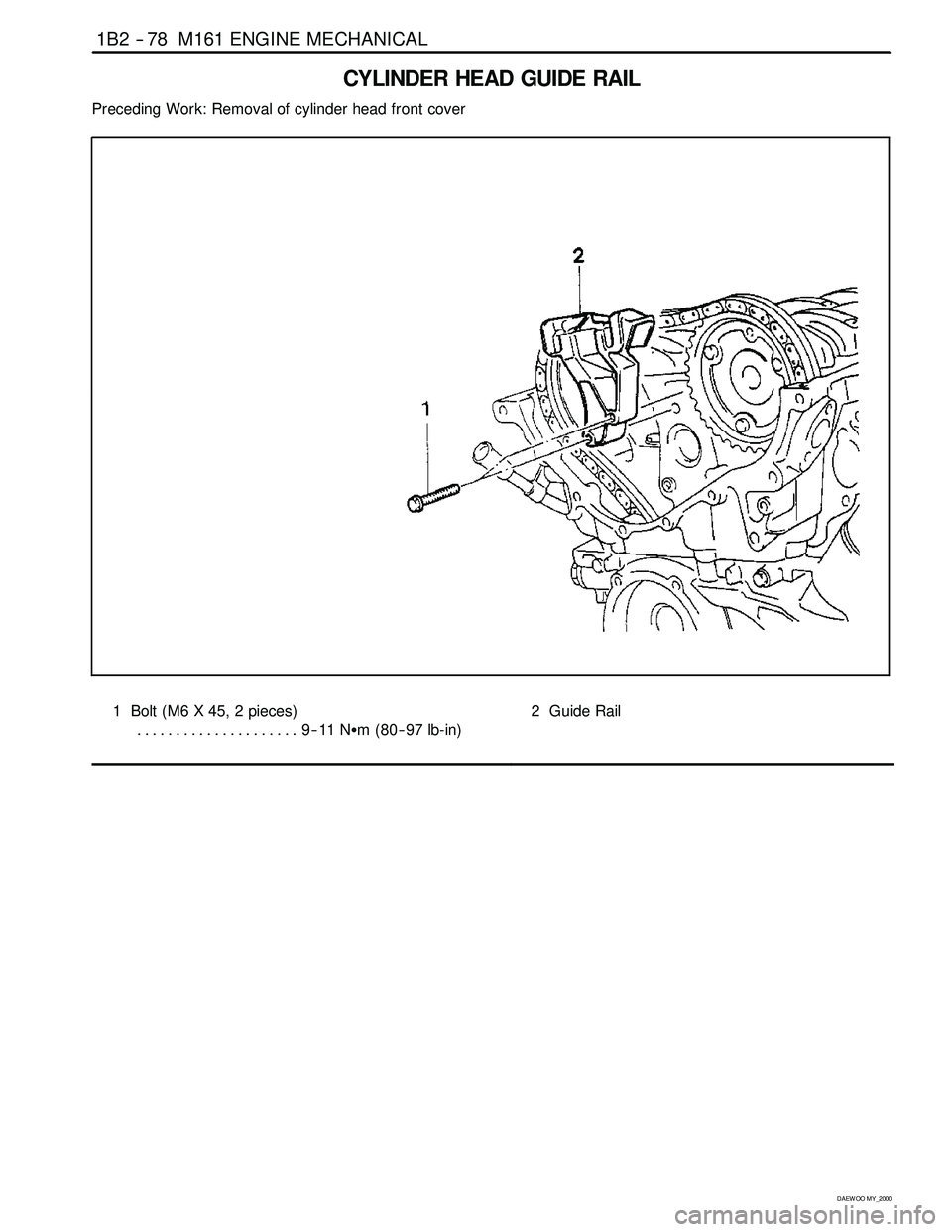
1B2 -- 78 M161 ENGINE MECHANICAL
D AEW OO M Y_2000
CYLINDER HEAD GUIDE RAIL
Preceding Work: Removal of cylinder head front cover
1 Bolt (M6 X 45, 2 pieces)
9--11 NSm (80-- 97 lb-in) .....................2 Guide Rail
Page 376 of 2053
M161 ENGINE MECHANICAL 1B2 -- 83
D AEW OO M Y_2000
PISTON
Preceding Work: Removal of engine
Removal of cylinder head
Removal of oil pan
Removal of oil pump
Removal of baffle plate
1 Connecting Rod Bearing Cap
2 Connecting Rod
3 Connecting Rod Bolt (M9 x 52, 8 pieces)
1ststep40NSm (30 lb-ft) ..................
2nd step 90°4Piston
5 Snap Ring
6 Piston Pin
Page 378 of 2053
M161 ENGINE MECHANICAL 1B2 -- 85
D AEW OO M Y_2000
1. Check the piston ring gap and apply the engine oil to
the piston pin and the connecting rod bushing.
2. Connect the piston and the connecting rod by press-
ing in the piston pin (6) and install the snap ring to the
groove.
3. Clean the cylinder bore, connecting rod bearing jour-
nal, connecting rod bearing shell and the piston and
coat them with engine oil.
4. Install the piston ring.
5. Install the piston so that the arrow on the piston head
faces to the forward of the vehicle.
6. After aligning the connecting rod and the bearing cap
mark (// or a number), tighten the bolts.
Installation Notice
TighteningTorque1st step: 40 NSm (30 lb-ft)TighteningTorque2nd step: 90°
Apply the engine oil to the bearing cap upper and low-
er bearing shells.
7. Check if the crankshaft rotates without any trouble by
rotating it.
Page 384 of 2053
M161 ENGINE MECHANICAL 1B2 -- 91
D AEW OO M Y_2000
Oil Circulation
1 Oil Strainer
2OilPump
3OilPan
4 Oil Non-- Return Valve
5 Oil Filter
6 Oil Filter Bypass Valve
7 Main Oil Gallery
8 Closing Ball (φ15mm)
9 Crankshaft
10 Connecting Rod Bearing
11 Crankshaft Bearing
12 Connecting Rod
13 Piston
14 Oil Spray (Piston Crown Area)
15 Non-- Return Valve (Crankcase)16 Oil Supply (To Chain Tensioner)
17 Camshaft
18 Cam Bearing
19 Valve
20 Oil Gallery (Supply Oil to Intake Tappet)
21 Oil Gallery (Supply Oil to Exhaust Tappet)
22 Ball (φ8mm)
23 Camshaft Plug
24 Seal
25 Screw Plug
26 Oil Return Gallery
(Cylinder Head and Crankcase)
27 Oil Return Gallery (Crankcase)
28 End Cover (φ20mm)
29 Oil Return Pipe


