head SSANGYONG KORANDO 1997 Service Owner's Guide
[x] Cancel search | Manufacturer: SSANGYONG, Model Year: 1997, Model line: KORANDO, Model: SSANGYONG KORANDO 1997Pages: 2053, PDF Size: 88.33 MB
Page 183 of 2053
1F1 -- 20 M162 ENGINE CONTROLS
D AEW OO M Y_2000
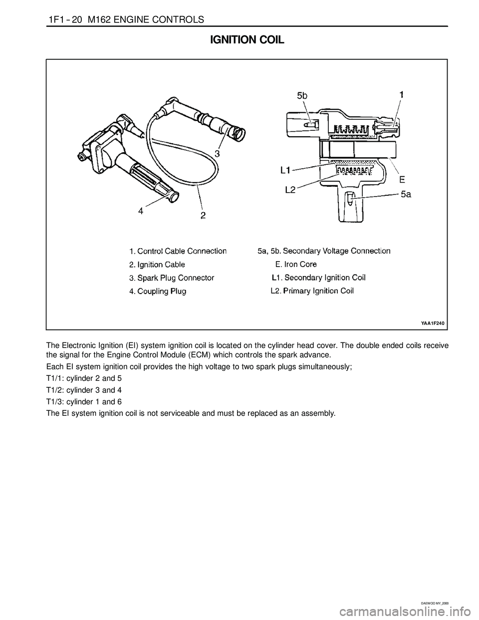
IGNITION COIL
YAA1F240
The Electronic Ignition (EI) system ignition coil is located on the cylinder head cover. The double ended coils receive
the signal for the Engine Control Module (ECM) which controls the spark advance.
Each EI system ignition coil provides the high voltage to two spark plugs simultaneously;
T1/1: cylinder 2 and 5
T1/2: cylinder 3 and 4
T1/3: cylinder 1 and 6
The EI system ignition coil is not serviceable and must be replaced as an assembly.
Page 263 of 2053
1F1 -- 100 M162 ENGINE CONTROLS
D AEW OO M Y_2000
KAA1F090
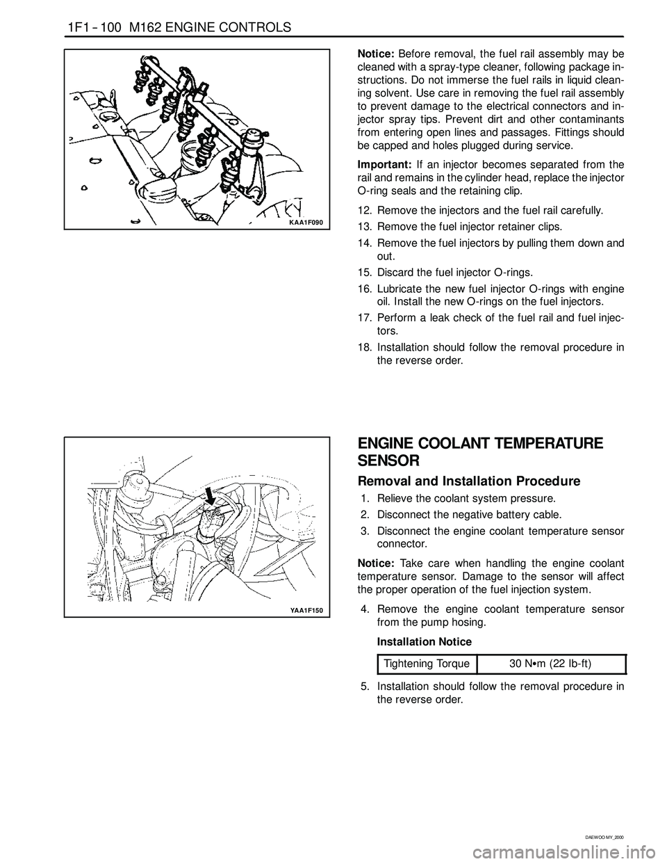
Notice:Before removal, the fuel rail assembly may be
cleaned with a spray-type cleaner, following package in-
structions. Do not immerse the fuel rails in liquid clean-
ing solvent. Use care in removing the fuel rail assembly
to prevent damage to the electrical connectors and in-
jector spray tips. Prevent dirt and other contaminants
from entering open lines and passages. Fittings should
be capped and holes plugged during service.
Important:If an injector becomes separated from the
rail and remains in the cylinder head, replace the injector
O-ring seals and the retaining clip.
12. Remove the injectors and the fuel rail carefully.
13. Remove the fuel injector retainer clips.
14. Remove the fuel injectors by pulling them down and
out.
15. Discard the fuel injector O-rings.
16. Lubricate the new fuel injector O-rings with engine
oil. Install the new O-rings on the fuel injectors.
17. Perform a leak check of the fuel rail and fuel injec-
tors.
18. Installation should follow the removal procedure in
the reverse order.
YAA1F150
ENGINE COOLANT TEMPERATURE
SENSOR
Removal and Installation Procedure
1. Relieve the coolant system pressure.
2. Disconnect the negative battery cable.
3. Disconnect the engine coolant temperature sensor
connector.
Notice:Take care when handling the engine coolant
temperature sensor. Damage to the sensor will affect
the proper operation of the fuel injection system.
4. Remove the engine coolant temperature sensor
from the pump hosing.
Installation Notice
Tightening Torque
30 NSm (22 Ib-ft)
5. Installation should follow the removal procedure in
the reverse order.
Page 283 of 2053

GENERAL ENGINE INFORMATION 1A2 -- 11
D AEW OO M Y_2000
CYLINDER PRESSURE LEAKAGE TEST
3 Engine Oil Filler Cap
5 Vibration Damper6 Cylinder Pressure Leakage Tester with
Connecting Hose
Permissible Pressure Leakage
At Whole EngineMax. 25 %
At Valve and Cylinder Head GasketMax. 10 %
At Piston and Piston RingMax. 20 %
Cylinder Number By Mark On Vibration Damper At TDC
TDC MarkOT (TDC)UT (BDC : 180°)
Cylinder Number1, 42, 3
Universal Tool
Cylinder Pressure Leakage TesterBosch, EFAW 210A
Sun, CLT 228
Page 287 of 2053
GENERAL ENGINE INFORMATION 1A2 -- 3
D AEW OO M Y_2000
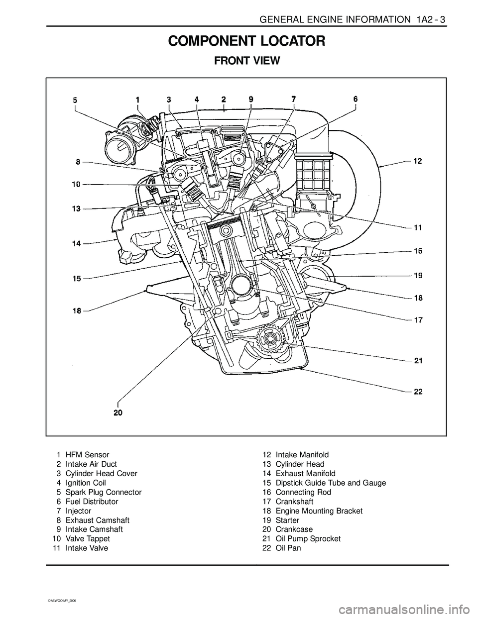
COMPONENT LOCATOR
FRONT VIEW
1 HFM Sensor
2 Intake Air Duct
3 Cylinder Head Cover
4 Ignition Coil
5 Spark Plug Connector
6 Fuel Distributor
7 Injector
8 Exhaust Camshaft
9 Intake Camshaft
10 Valve Tappet
11 Intake Valve12 Intake Manifold
13 Cylinder Head
14 Exhaust Manifold
15 Dipstick Guide Tube and Gauge
16 Connecting Rod
17 Crankshaft
18 Engine Mounting Bracket
19 Starter
20 Crankcase
21 Oil Pump Sprocket
22 Oil Pan
Page 294 of 2053
D AEW OO M Y_2000
SECTION 1B2
M161 ENGINE MECHANICAL
CAUTION: Disconnect the negative battery cable before removing or installing any electrical unit or when a
tool or equipment could easily come in contact with exposed electrical terminals. Disconnecting this cable
will help prevent personal injury and damage to the vehicle. The ignition must also be in LOCK unless other -
wise noted.
TABLE OF CONTENTS
Specifications 1B2 -- 2............................
Fastener Tightening Specifications 1B2 -- 2..........
Special Tools 1B2 -- 4.............................
Special Tools Table 1B2-- 4.......................
Maintenance and Repair 1B2 -- 7...................
On-- Vehicle Service 1B2-- 7.........................
Engine Assembly 1B2-- 7.........................
Crankcase Ventilation System 1B2-- 14.............
Generator 1B2-- 18..............................
Engine Mount 1B2-- 19...........................
Poly V-- Belt 1B2 -- 20.............................
Tensioning Device 1B2-- 22.......................
Tensioning Device Shock Absorber 1B2-- 23........
Poly V-- Belt Inspection 1B2-- 24...................
Cylinder Head Cover 1B2-- 26.....................
Cylinder Head Front Cover 1B2 -- 28...............
Cylinder Head 1B2-- 30...........................
Timing Gear Case Cover 1B2-- 34.................
Crankshaft Sealing Rear Cover 1B2-- 37...........
Belt Pulley and Vibration Damper 1B2-- 39..........
Crankshaft Front Radial Seal 1B2-- 42.............
Crankshaft Rear Radial Seal 1B2-- 44..............
Crankshaft 1B2-- 45.............................
Flywheel / Driven Plate 1B2 -- 51...................
Camshaft Adjuster 1B2-- 54.......................Camshaft Sprocket Bolt 1B2-- 57..................
Camshaft 1B2-- 58..............................
Camshaft Timing Position 1B2 -- 61................
Valve Spring 1B2 -- 63............................
Valve Stem Seal 1B2-- 67........................
Chain Tensioner 1B2-- 68.........................
Timing Chain 1B2-- 72............................
Tensioning Rail 1B2-- 77..........................
Cylinder Head Guide Rail 1B2-- 78.................
Crankcase Guide Rail 1B2-- 80....................
Crankshaft Sprocket 1B2-- 81.....................
Piston 1B2-- 83..................................
Connecting Rod 1B2-- 86.........................
Piston Ring 1B2 -- 88.............................
Oil Pan 1B2-- 90.................................
Engine Oil and Oil Filter Element 1B2-- 92..........
Oil Pump 1B2-- 95...............................
Oil Pressure Relief Valve 1B2-- 97.................
Oil Non-Return Valve 1B2-- 98....................
Oil Dipstick Guide Tube 1B2-- 99..................
Unit Repair 1B2 -- 100............................
Core Plugs in Crankcase 1B2-- 100................
Cylinder Bore 1B2-- 102..........................
Crankcase Mating Surface 1B2-- 104..............
Cylinder Head Mating Surface 1B2-- 106...........
Page 295 of 2053
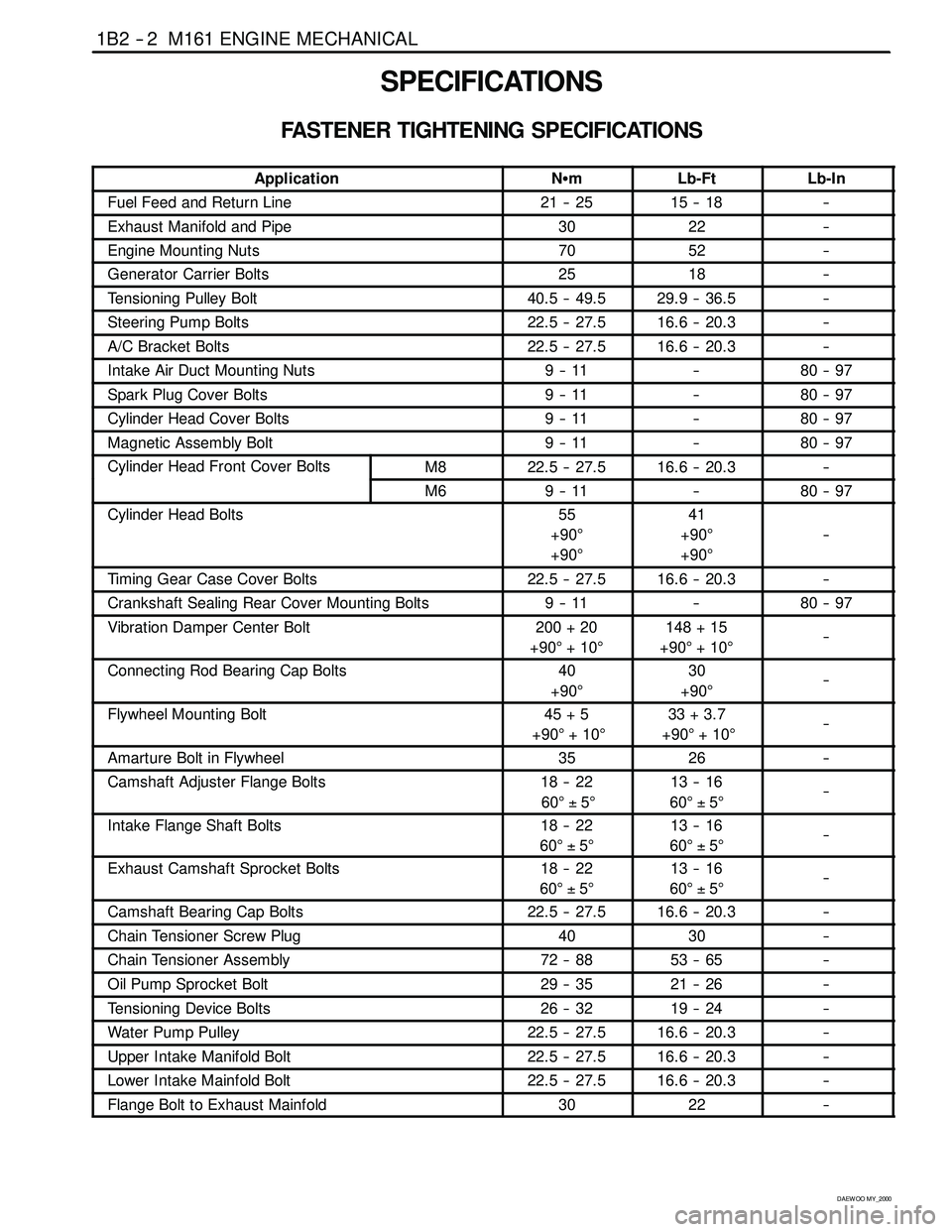
1B2 -- 2 M161 ENGINE MECHANICAL
D AEW OO M Y_2000
SPECIFICATIONS
FASTENER TIGHTENING SPECIFICATIONS
ApplicationNSmLb-FtLb-In
Fuel Feed and Return Line21 -- 2515 -- 18--
Exhaust Manifold and Pipe3022--
Engine Mounting Nuts7052--
Generator Carrier Bolts2518--
Tensioning Pulley Bolt40.5 -- 49.529.9 -- 36.5--
Steering Pump Bolts22.5 -- 27.516.6 -- 20.3--
A/C Bracket Bolts22.5 -- 27.516.6 -- 20.3--
Intake Air Duct Mounting Nuts9--11--80 -- 97
Spark Plug Cover Bolts9--11--80 -- 97
Cylinder Head Cover Bolts9--11--80 -- 97
Magnetic Assembly Bolt9--11--80 -- 97
Cylinder Head Front Cover BoltsM822.5 -- 27.516.6 -- 20.3--y
M69--11--80 -- 97
Cylinder Head Bolts55
+90°
+90°41
+90°
+90°
--
Timing Gear Case Cover Bolts22.5 -- 27.516.6 -- 20.3--
Crankshaft Sealing Rear Cover Mounting Bolts9--11--80 -- 97
Vibration Damper Center Bolt200 + 20
+90°+10°148 + 15
+90°+10°--
Connecting Rod Bearing Cap Bolts40
+90°30
+90°--
Flywheel Mounting Bolt45 + 5
+90°+10°33 + 3.7
+90°+10°--
Amarture Bolt in Flywheel3526--
Camshaft Adjuster Flange Bolts18 -- 22
60°±5°13 -- 16
60°±5°--
Intake Flange Shaft Bolts18 -- 22
60°±5°13 -- 16
60°±5°--
Exhaust Camshaft Sprocket Bolts18 -- 22
60°±5°13 -- 16
60°±5°--
Camshaft Bearing Cap Bolts22.5 -- 27.516.6 -- 20.3--
Chain Tensioner Screw Plug4030--
Chain Tensioner Assembly72 -- 8853 -- 65--
Oil Pump Sprocket Bolt29 -- 3521 -- 26--
Tensioning Device Bolts26 -- 3219 -- 24--
Water Pump Pulley22.5 -- 27.516.6 -- 20.3--
Upper Intake Manifold Bolt22.5 -- 27.516.6 -- 20.3--
Lower Intake Mainfold Bolt22.5 -- 27.516.6 -- 20.3--
Flange Bolt to Exhaust Mainfold3022--
Page 307 of 2053

1B2 -- 14 M161 ENGINE MECHANICAL
D AEW OO M Y_2000
CRANKCASE VENTILATIONSYSTEM
Operation at Idling and Mid- Load
1 HFM Sensor
2 Cylinder Head Cover
3 Oil Spearation Chamber (Full-- Load or Over
Mid-- Load)
4 Intake Air Duct (Cross Pipe)
5 Vent Line (Full-- Load or Over Mid-- Load)
6 Throttle Valve
7 Restrictor, Diameter 1.1mm
(Mid-- Load at Idling)
8 Intake Manifold
9 Vent Line (Mid-- Load at Idling)
10 Air Conditioner Bracket11 Oil Separation Chamber (Mid-- Load at Idling)
12 Crank Chamber
13 Oil Return Pipe
14 Oil Pan
15 Timing Gear Case Cover
16 Crankcase
17 Chain Housing
A Fresh Air
BBlow--byGas
D Vent Connection
Page 308 of 2053

M161 ENGINE MECHANICAL 1B2 -- 15
D AEW OO M Y_2000
Operation at Idling and Mid- Load
DThe throttle valve (6) is closed or very partially
opened, and the vacuum pressure in intake manifold
is high.
The blow-- by gas and the fresh air that is additionally
supplied through the vent connection (D) in the crank-
case in partial load gets supplied to the combustion
chamber from the crank chamber (12) through the oil
separation chamber (11), air -- conditioner bracket
(10), vent line (9), and restrictor (7) mounted to the
cylinder head.
The circulated engine oil returns to the oil pan through
the oil return pipe (13) at the bottom of oil separation
chamber (11).
The fresh air gets supplied to the crank chamber (12)
through the HFM sensor (1), intake air duct (4), vent
line (5), oil separation chamber (3), chain housing
(17), and the timing gear case cover (15).
The additional supply of the fresh air is needed to pre-
vent from forming the residues of the engine oil.
Page 309 of 2053

1B2 -- 16 M161 ENGINE MECHANICAL
D AEW OO M Y_2000
Operation When Full- Load at Partial Load
1 HFM Sensor
2 Cylinder Head Cover
3 Oil Spearation Chamber (Full-- Load or Over
Mid-- Load)
4 Intake Air Duct (Cross Pipe)
5 Vent Line (Full-- Load or Over Mid-- Load)
6 Throttle Valve
7 Restrictor, Diameter 1.1mm
(Mid-- Load at Idling)
8 Intake Manifold
9 Vent Line (Mid-- Load at Idling)
10 Air Conditioner Bracket11 Oil Separation Chamber (Mid-- Load at Idling)
12 Crank Chamber
13 Oil Return Pipe
14 Oil Pan
15 Timing Gear Case Cover
16 Crankcase
17 Chain Housing
A Fresh Air
CBlow--byGas
D Vent Connection
Page 319 of 2053

1B2 -- 26 M161 ENGINE MECHANICAL
D AEW OO M Y_2000
CYLINDER HEAD COVER
1 Spark Plug Cover
2 Spark Plug Connector
3 Bolt(M6X45:4pieces,M6X60:6pieces)
9--11 NSm (80-- 97 lb-in) .....................4 Cylinder Head Cover
5 Gasket Replace...........................