torque SSANGYONG KORANDO 1997 Service Manual PDF
[x] Cancel search | Manufacturer: SSANGYONG, Model Year: 1997, Model line: KORANDO, Model: SSANGYONG KORANDO 1997Pages: 2053, PDF Size: 88.33 MB
Page 267 of 2053
1F1 -- 104 M162 ENGINE CONTROLS
D AEW OO M Y_2000
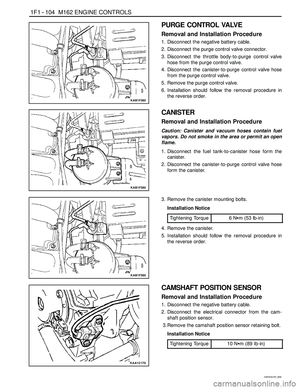
KAB1F380
PURGE CONTROL VALVE
Removal and Installation Procedure
1. Disconnect the negative battery cable.
2. Disconnect the purge control valve connector.
3. Disconnect the throttle body-to-purge control valve
hose from the purge control valve.
4. Disconnect the canister-to-purge control valve hose
from the purge control valve.
5. Remove the purge control valve.
6. Installation should follow the removal procedure in
the reverse order.
KAB1F390
CANISTER
Removal and Installation Procedure
Caution: Canister and vacuum hoses contain fuel
vapors. Do not smoke in the area or permit an open
flame.
1. Disconnect the fuel tank-to-canister hose form the
canister.
2. Disconnect the canister-to-purge control valve hose
form the canister.
KAB1F380
3. Remove the canister mounting bolts.
Installation Notice
Tightening Torque
6NSm (53 lb-in)
4. Remove the canister.
5. Installation should follow the removal procedure in
the reverse order.
KAA1C170
CAMSHAFT POSITION SENSOR
Removal and Installation Procedure
1. Disconnect the negative battery cable.
2. Disconnect the electrical connector from the cam-
shaft position sensor.
3. Remove the camshaft position sensor retaining bolt.
Installation Notice
Tightening Torque
10 NSm (89 Ib-in)
Page 268 of 2053
M162 ENGINE CONTROLS 1F1 -- 105
D AEW OO M Y_2000
4. Check the O-ring for damage and replace it if neces-
sary.
5. Installation should follow the removal procedure in
the reverse order.
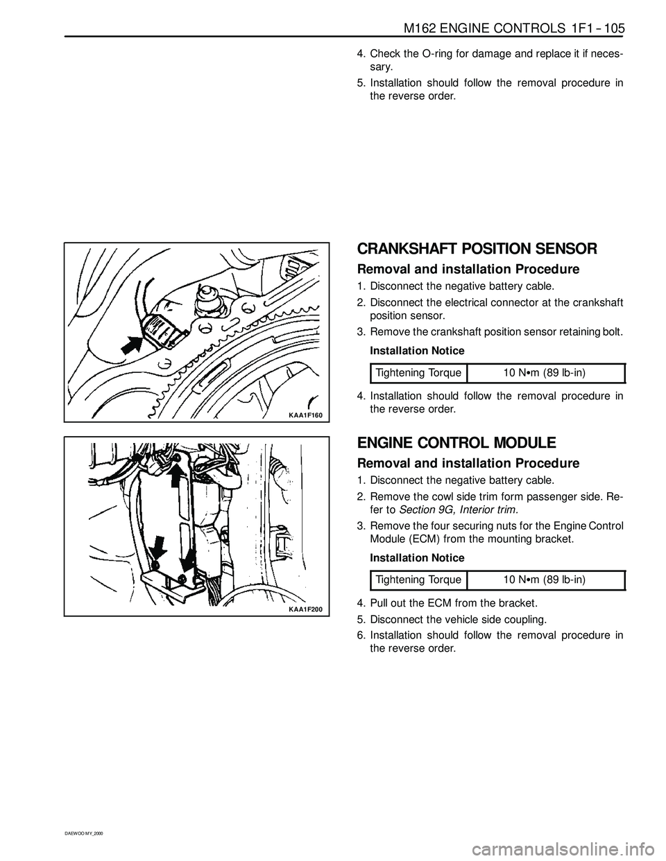
KAA1F160
CRANKSHAFT POSITION SENSOR
Removal and installation Procedure
1. Disconnect the negative battery cable.
2. Disconnect the electrical connector at the crankshaft
position sensor.
3. Remove the crankshaft position sensor retaining bolt.
Installation Notice
Tightening Torque
10 NSm (89 lb-in)
4. Installation should follow the removal procedure in
the reverse order.
KAA1F200
ENGINE CONTROL MODULE
Removal and installation Procedure
1. Disconnect the negative battery cable.
2. Remove the cowl side trim form passenger side. Re-
fer toSection 9G, Interior trim.
3. Remove the four securing nuts for the Engine Control
Module (ECM) from the mounting bracket.
Installation Notice
Tightening Torque
10 NSm (89 lb-in)
4. Pull out the ECM from the bracket.
5. Disconnect the vehicle side coupling.
6. Installation should follow the removal procedure in
the reverse order.
Page 272 of 2053

1G1 -- 4 M162 ENGINE INTAKE & EXHAUST
D AEW OO M Y_2000
Removal and Installation Procedure
1. Disconnect the HFM sensor and the air cleaner by
prying up the clamp.
2. Remove the air cleaner mounting bolt.
Installation Notice
Tightening Torque
22.5 -- 27.5 NSm
(16.6 -- 20.3 lb-ft)
3. Remove air intake shield upper cover, and then re-
move the air cleaner from rubber bearing on bracket.
Notice:For installation, exactly seat the air cleaner into
the rubber bearing.
4. Installation should follow the removal procedure in
the reverse order.
Page 276 of 2053
1G1 -- 8 M162 ENGINE INTAKE & EXHAUST
D AEW OO M Y_2000
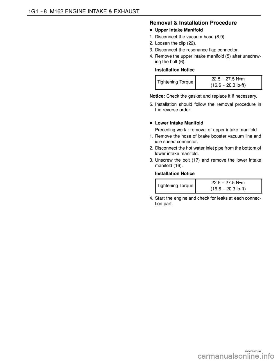
Removal & Installation Procedure
DUpper Intake Manifold
1. Disconnect the vacuum hose (8,9).
2. Loosen the clip (22).
3. Disconnect the resonance flap connector.
4. Remove the upper intake manifold (5) after unscrew-
ing the bolt (6).
Installation Notice
Tightening Torque
22.5 -- 27.5 NSm
(16.6 -- 20.3 lb-ft)
Notice:Check the gasket and replace it if necessary.
5. Installation should follow the removal procedure in
the reverse order.
DLower Intake Manifold
Preceding work : removal of upper intake manifold
1. Remove the hose of brake booster vacuum line and
idle speed connector.
2. Disconnect the hot water inlet pipe from the bottom of
lower intake manifold.
3. Unscrew the bolt (17) and remove the lower intake
manifold (16).
Installation Notice
Tightening Torque
22.5 -- 27.5 NSm
(16.6 -- 20.3 lb-ft)
4. Start the engine and check for leaks at each connec-
tion part.
Page 278 of 2053

1G1 -- 10 M162 ENGINE INTAKE & EXHAUST
D AEW OO M Y_2000
Function Description
A pneumatically actuated resonance flap (5) is located
on the intake manifold, and will be opened and closed by
load, which operates resonance flap according to engine
and controlled by ECU and rpm.
1. Resonance flap closed (at idle/partial load : less
than 3,800/rpm)
The switch valve (7) will be adjusted by ECU and res-
onance flapwill be closed. By increasing air flow pas-
sage through dividing intaking air flow toward both air
collection housing (8). This leads to a signficant in-
crease in the torque in the lower speed range.
2. Resonance flap open (at full load:over 3,800/rpm)
The switch valve (7) will not be adjusted by ECU and
resonance flap (5) will beopen. The colllected air in
the air collection housing (8)will not be divided and
intaking air passage will be shorten.
Page 280 of 2053
1G1 -- 12 M162 ENGINE INTAKE & EXHAUST
D AEW OO M Y_2000
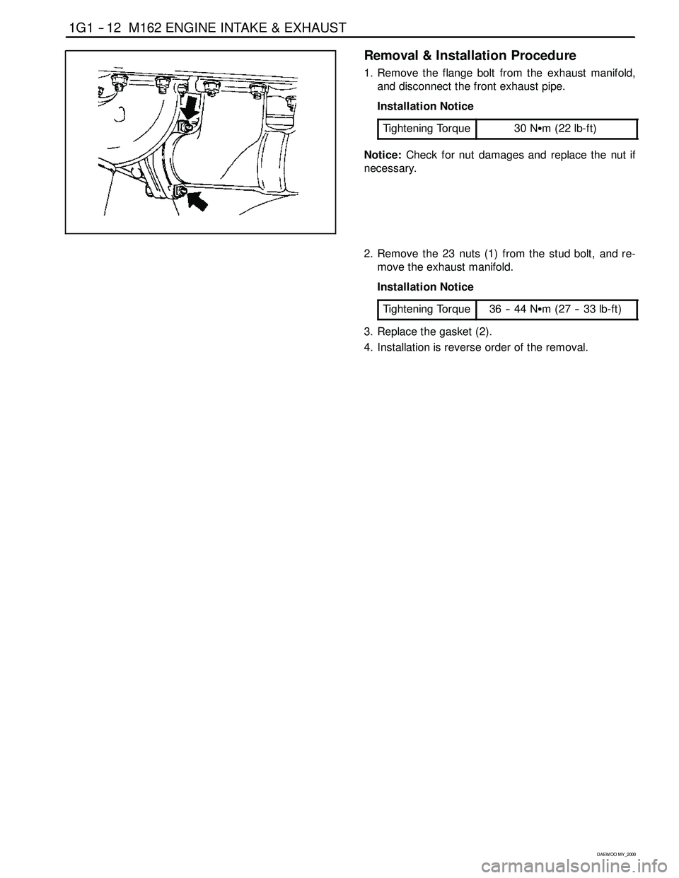
Removal & Installation Procedure
1. Remove the flange bolt from the exhaust manifold,
and disconnect the front exhaust pipe.
Installation Notice
Tightening Torque
30 NSm (22 lb-ft)
Notice:Check for nut damages and replace the nut if
necessary.
2. Remove the 23 nuts (1) from the stud bolt, and re-
move the exhaust manifold.
Installation Notice
Tightening Torque
36 -- 44 NSm (27 -- 33 lb-ft)
3. Replace the gasket (2).
4. Installation is reverse order of the removal.
Page 286 of 2053
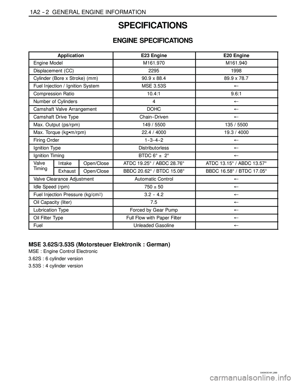
1A2 -- 2 GENERAL ENGINE INFORMATION
D AEW OO M Y_2000
SPECIFICATIONS
ENGINE SPECIFICATIONS
ApplicationE23 EngineE20 Engine
Engine ModelM161.970M161.940
Displacement (CC)22951998
Cylinder (Bore x Stroke)(mm)90.9 x 88.489.9 x 78.7
Fuel Injection / Ignition SystemMSE 3.53S←
Compression Ratio10.4:19.6:1
Number of Cylinders4←
Camshaft Valve ArrangementDOHC←
Camshaft Drive TypeChain-- Driven←
Max. Output (ps/rpm)149 / 5500135 / 5500
Max. Torque (kgSm/rpm)22.4 / 400019.3 / 4000
Firing Order1--3--4--2←
Ignition TypeDistributorless←
Ignition TimingBTDC 6°±2°←
Va lv e
Tii
IntakeOpen/CloseATDC 19.25°/ ABDC 28.76°ATDC 13.15°/ ABDC 13.57°
Tim in gExhaustOpen/CloseBBDC 20.62°/ BTDC 15.08°BBDC 16.58°/ BTDC 17.05°
Valve Clearance AdjustmentAutomatic Control←
Idle Speed (rpm)750±50←
Fuel Injection Pressure (kg/cm@)3.2 -- 4.2←
Oil Capacity (liter)7.5←
Lubrication TypeForced by Gear Pump←
Oil Filter TypeFull Flow with Paper Filter←
FuelUnleaded Gasoline←
MSE 3.62S/3.53S (Motorsteuer Elektronik : German)
MSE : Engine Control Electronic
3.62S : 6 cylinder version
3.53S : 4 cylinder version
Page 296 of 2053
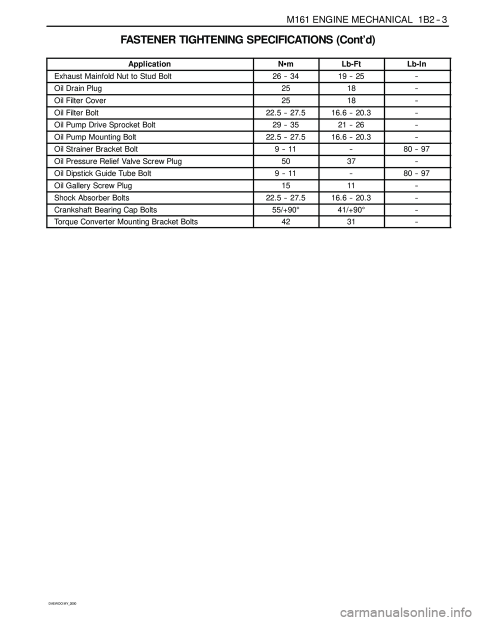
M161 ENGINE MECHANICAL 1B2 -- 3
D AEW OO M Y_2000
FASTENER TIGHTENING SPECIFICATIONS (Cont’d)
ApplicationNSmLb-FtLb-In
Exhaust Mainfold Nut to Stud Bolt26 -- 3419 -- 25--
Oil Drain Plug2518--
Oil Filter Cover2518--
Oil Filter Bolt22.5 -- 27.516.6 -- 20.3--
Oil Pump Drive Sprocket Bolt29 -- 3521 -- 26--
Oil Pump Mounting Bolt22.5 -- 27.516.6 -- 20.3--
Oil Strainer Bracket Bolt9--11--80 -- 97
Oil Pressure Relief Valve Screw Plug5037--
Oil Dipstick Guide Tube Bolt9--11--80 -- 97
Oil Gallery Screw Plug1511--
Shock Absorber Bolts22.5 -- 27.516.6 -- 20.3--
Crankshaft Bearing Cap Bolts55/+90°41/+90°--
Torque Converter Mounting Bracket Bolts4231--
Page 301 of 2053

1B2 -- 8 M161 ENGINE MECHANICAL
D AEW OO M Y_2000
Removal & Installation Procedure
1. Disconnect the negative terminal of battery.
2. Remove the hood.
3. Remove the under cover.
Installation Notice
Tightening Torque
28 -- 47 NSm (21 -- 35 lb-ft)
4. Disconnect the coupling of HFM sensor and remove
the air cleaner cross pipe.
5. Remove the air cleaner cover. Remove the mounting
bolts and air cleaner housing and element assembly.
6. Loosen the radiator drain cock and drain the coolant.
Notice:Open the coolant reservoir cap.
Page 302 of 2053

M161 ENGINE MECHANICAL 1B2 -- 9
D AEW OO M Y_2000
7. Loosen the cylinder block drain plug and then drain
the coolant completely.
Installation Notice
Tightening Torque
30 NSm (22 lb-ft)
Notice:Replace the seal before installation of the drain
plug.
8. Remove the cooling fan shroud. Refer toSection
1D2, Engine Cooling.
9. Disconnect the each hose from radiator.
10. Remove the upper mounting bolts of radiator and
then remove the radiator.