section 2c SSANGYONG KORANDO 1997 Service Repair Manual
[x] Cancel search | Manufacturer: SSANGYONG, Model Year: 1997, Model line: KORANDO, Model: SSANGYONG KORANDO 1997Pages: 2053, PDF Size: 88.33 MB
Page 1 of 2053
D AEW OO M Y_2000
SECTION 0B
GENERAL INFORMATION
TABLE OF CONTENTS
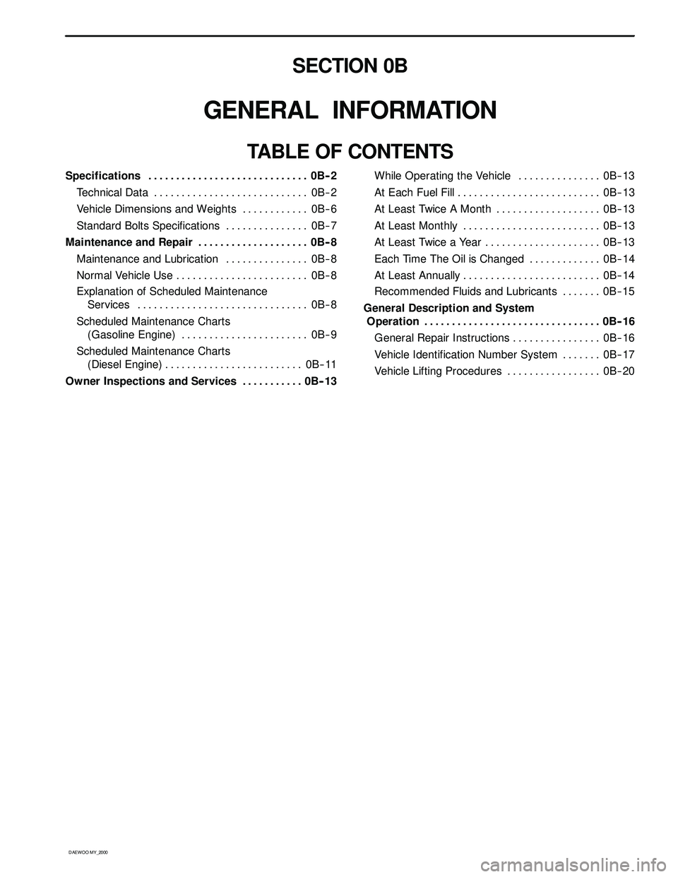
Specifications 0B-- 2.............................
Technical Data 0B-- 2............................
Vehicle Dimensions and Weights 0B-- 6............
Standard Bolts Specifications 0B-- 7...............
Maintenance and Repair 0B-- 8....................
Maintenance and Lubrication 0B-- 8...............
Normal Vehicle Use 0B-- 8........................
Explanation of Scheduled Maintenance
Services 0B-- 8...............................
Scheduled Maintenance Charts
(Gasoline Engine) 0B-- 9.......................
Scheduled Maintenance Charts
(Diesel Engine) 0B-- 11.........................
Owner Inspections and Services 0B-- 13...........While Operating the Vehicle 0B-- 13...............
At Each Fuel Fill 0B-- 13..........................
At Least Twice A Month 0B-- 13...................
At Least Monthly 0B-- 13.........................
At Least Twice a Year 0B-- 13.....................
Each Time The Oil is Changed 0B-- 14.............
At Least Annually 0B-- 14.........................
Recommended Fluids and Lubricants 0B-- 15.......
General Description and System
Operation 0B--16................................
General Repair Instructions 0B-- 16................
Vehicle Identification Number System 0B-- 17.......
Vehicle Lifting Procedures 0B-- 20.................
Page 8 of 2053
0B -- 8 GENERAL INFORMATION
D AEW OO M Y_2000
MAINTENANCE AND REPAIR
MAINTENANCE AND
LUBRICATION
NORMAL VEHICLE USE
The maintenance instructions contained in the mainte-
nance schedule are based on the assumption that the
vehicle will be used for the following reasons:
DTo carry passengers and cargo within the limitation of
the tire inflation prassure. Refer to “Tire and Wheel” in
section 2E.
DTo be driven on reasonable road surfaces and within
legal operating limits.
EXPLANATION OF SCHEDULED
MAINTENANCE SERVICES
The services listed in the maintenance schedule are fur-
ther explained below. When the following maintenance
services are performed, make sure all the parts are re-
placed and all the necessary repairs are done before
driving the vehicle. Always use the proper fluid and lubri-
cants.
Engine Oil and Oil Filter Change
Always use above the API SH grade or recommended
engine oil.
Engine Oil Viscosity
Engine oil viscosity (thickness) has an effect on fuel
economy and cold weather operation. Lower viscosity
engine oils can provide better fuel economy and cold
weather performance; however, higher temperature
weather conditions require higher viscosity engine oils
for satisfactory lubrication. Using oils of any viscosity
other than those viscosities recommended could result
in engine damage.
Cooling System Service
Drain, flush and refill the system with new coolant. Refer
to “Recommended Fluids And Lubricants“ in this sec-
tion.
Air Cleaner Element Replacement
Clean the air cleaner element every.
DGasoline Engine : 15,000km (10,000 miles)
DDiesel Engine : 10,000km (6,000 miles)
Replace the air cleaner element every .
DGasoline Engine : 60,000km (36,000 miles)DDiesel Engine : 30,000km (18,000 miles)
Replace the air cleaner more often under dusty condi-
tions.
Fuel Filter Replacement
Replace the engine fuel filter every.
DGasoline Engine : 60,000km (36,000 miles)
DDiesel Engine : 45,000km (24,000 miles)
Spark Plug Replacement
Replace spark plugs with same type.
DType : BOSCH : F8DC4
BERU : 14F-- 8DU4
Champion : C11YCC
DGap : 0.8±0.1 mm
Spark Plug Wire Replacement
Clean wires and inspect them for burns, cracks or other
damage. Check the wire boot fit at the Distributor and at
the spark plugs. Replace the wires as needed.
Brake System Service
Check the disc brake pads or the drum brake linings.
Check the pad and the lining thickness carefully.
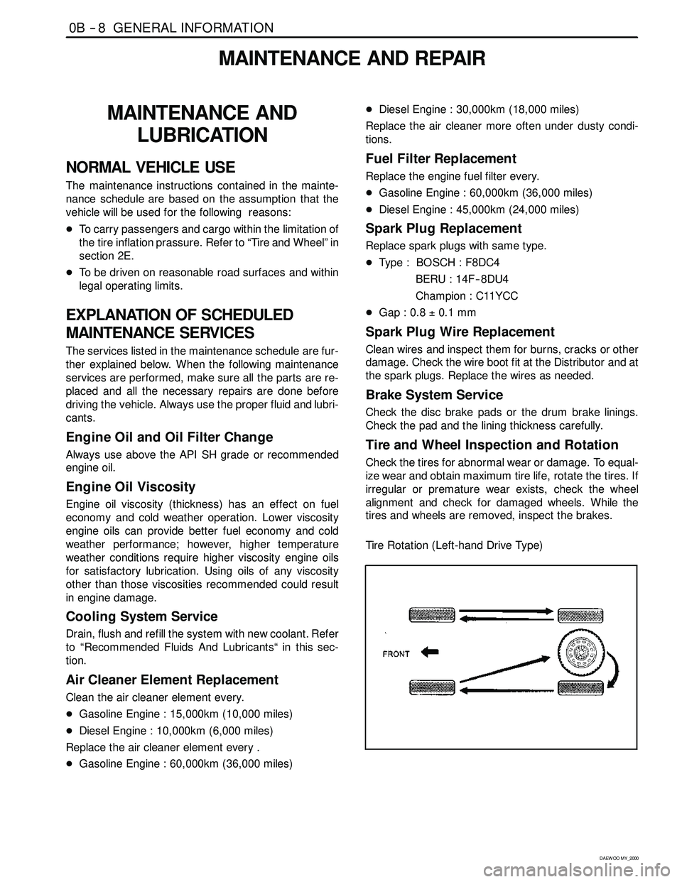
Tire and Wheel Inspection and Rotation
Check the tires for abnormal wear or damage. To equal-
ize wear and obtain maximum tire life, rotate the tires. If
irregular or premature wear exists, check the wheel
alignment and check for damaged wheels. While the
tires and wheels are removed, inspect the brakes.
Tire Rotation (Left-hand Drive Type)
Page 13 of 2053
GENERAL INFORMATION 0B -- 13
D AEW OO M Y_2000
OWNER INSPECTIONS AND SERVICES
WHILE OPERATING THE VEHICLE
Horn Operation
Blow the horn occasionally to make sure it works. Check
all the button locations.
Brake System Operation
Be alert for abnormal sounds, increased brake pedal
travel or repeated puling to one side when braking. Also,
if the brake warning light goes on, or flashes, something
may be wrong with part of the brake system.
Exhaust System Operation
Be alert to any changes inthe sound of the system or
the smell of the fumes. These are signs that the system
may be leaking or overheating. Have the system in-
spected and repaired immediately.
Tires, Wheels and Alignment Operation
Be alert to any vibration of the steering wheel or the
seats at normal highway speeds. This may mean a
wheel needs to be balanced. Also, a pull right or left on a
straight, level road may show the need for a tire pres-
sure adjustment or a wheel alignment.
Steering System Operation
Be alert to changes in the steering action. An inspection
is needed when the steering wheel is hard to turn or has
too much free play, or is unusual sounds are noticed
when turning or parking.
Headlight Aim
Take note of the light pattern occasionally. Adjust the
headlights if the beams seem improperly aimed.
AT EACH FUEL FILL
A fluid loss in any (except windshield washer) system
may indicate a problem. Have the system inspected and
repaired immediately.
Engine Oil Level
Check the oil level and add oil if necessary. The best
time to check the engine oil level is when the oil is warm.
1. After stopping the engine, wait a few minutes for the
oil to drain back to the oil pan.
2. Pull out the oil level indicator (dip stick).
3. Wipe it clean, and push the oil level indicator back
down all the way.
4. Pull out the oil level indicator and look at the oil level
on it.
5. Add oil, if needed, to keep the oil level above the low-
er mark. Avoid overfilling theengine, since this may
cause engine damage.
6. Push the indicator all the way back down into the en-
gine after taking the reading.If you check the oil level when the oil is cold, do not run
the engine first. The cold oil will not drain back to the pan
fast enough to give a true oil level reading.
Engine Coolant Level and Condition
Check the coolant level in the coolant reservoir tank and
add coolant if necessary. Inspect the coolant. Replace
dirty or rusty coolant.
Windshield Washer Fluid Level
Check the washer fluid level in the reservoir. Add fluid if
necessary.
AT LEAST TWICE A MONTH
Tire And Wheel Inspection and Pressure
Check
Check the tire for abnormal wear or damage. Also check
for damaged wheels. Check the tire pressure when the
tires are cold ( check the spare also, unless it is a stow-
away). Maintain the recommended pressures. Refer to
“Tire and Wheel” is in section 0B.
AT LEAST MONTHLY
Light Operation
Check the operation of the license plate light, the head-
lights (including the high beams), the parking lights, the
fog lights, the taillight, the brake lights, the turn signals,
the backup lights and the hazard warning flasher.
Fluid Leak Check
Periodically inspect the surface beneath the vehicle for
water, oil, fuel or other fluids, after the vehicle has been
parked for a while. Water dripping from the air condition-
ing system after use is normal. If you notice fuel leaks or
fumes, find the cause and correct it at once.
AT LEAST TWICE A YEAR
Power Steering System Reservoir Level
Check the power steering fluid level. Keep the power
steering fluid at the proper level. Refer to Section 6A,
Power Steering System.
Brake Master Cylinder Reservoir Level
Check the fluid and keep it at the proper level. A low fluid
level can indicate worn disc brake pads which may need
to be serviced. Check the breather hole in the reservoir
cover to be free from dirt and check for an open pas-
sage.
Weather- Strip Lubrication
Apply a thin film silicone grease using a clean cloth.
Page 21 of 2053
D AEW OO M Y_2000
SECTION 1
ENGINE
SECTION 1A1 (M162 ENGINE)
GENERAL ENGINE INFORMATION
TABLE OF CONTENTS
Specifications 1A1 -- 2............................
Engine Specifications 1A1-- 2.....................
Component Locator 1A1 -- 3.......................
Front View 1A1 -- 3...............................
Side View 1A1-- 4...............................
Performance Curve 1A1-- 5........................
E32 Engine 1A1-- 5..............................
Diagnosis 1A1 -- 6.................................
Oil Leak Diagnosis 1A1-- 6........................Engine Cranking at The
FrontofCrankshaft 1A1--7.....................
Compression Pressure Test 1A1-- 8...............
Cylinder Pressure Leakage Test 1A1-- 10...........
General Information 1A1 -- 12......................
Cleanliness and Care 1A1 -- 12....................
On-- Engine Service 1A1-- 12......................
Page 33 of 2053
D AEW OO M Y_2000
SECTION 1B1
M162 ENGINE MECHANICAL
CAUTION: Disconnect the negative battery cable before removing or installing any electrical unit or when a
tool or equipment could easily come in contact with exposed electrical terminals. Disconnecting this cable
will help prevent personal injury and damage to the vehicle. The ignition must also be in LOCK unless other -
wise noted.
TABLE OF CONTENTS
Specifications 1B1 -- 2............................
Fastener Tightening Specifications 1B1 -- 2..........
Special Tools 1B1 -- 4.............................
Special Tools Table 1B1-- 4.......................
Maintenance and Repair 1B1 -- 7...................
On-- Vehicle Service 1B1-- 7.........................
Engine Assembly 1B1-- 7.........................
Crankcase Ventilation System 1B1-- 14.............
Generator 1B1-- 16..............................
Engine Mount 1B1-- 17...........................
Poly V-- Belt 1B1 -- 18.............................
Tensioning Device 1B1-- 20.......................
Poly V-- Belt Inspection 1B1-- 21...................
Cylinder Head Cover 1B1-- 24.....................
Cylinder Head Front Cover 1B1 -- 26...............
Cylinder Head 1B1-- 28...........................
Timing Gear Case Cover 1B1-- 31.................
Crankshaft Sealing Rear Cover 1B1-- 33...........
Belt Pulley and Vibration Damper 1B1-- 35..........
Crankshaft Front Radial Seal 1B1-- 38.............
Crankshaft Rear Radial Seal 1B1-- 40..............
Crankshaft 1B1-- 41.............................
Flywheel / Driven Plate 1B1 -- 47...................
Camshaft Adjuster 1B1-- 50.......................
Camshaft Sprocket Bolt 1B1-- 52..................
Camshaft 1B1-- 54..............................
Camshaft Timing Position 1B1 -- 59................Valve Spring 1B1 -- 62............................
Valve Stem Seal 1B1-- 66........................
Chain Tensioner 1B1-- 67.........................
Timing Chain 1B1-- 70............................
Tensioning Rail 1B1-- 75..........................
Cylinder Head Guide Rail 1B1-- 76.................
Crankcase Guide Rail 1B1-- 77....................
Crankshaft Sprocket 1B1-- 78.....................
Piston 1B1-- 80..................................
Connecting Rod 1B1-- 83.........................
Piston Ring 1B1 -- 85.............................
Engine Oil Specification 1B1-- 87..................
Oil Pan 1B1-- 88.................................
Engine Oil and Oil Filter Element 1B1-- 90..........
Oil Filter 1B1-- 92................................
Oil Pump 1B1-- 94...............................
Oil Pressure Relief Valve 1B1-- 96.................
Oil Non-Return Valve 1B1-- 97....................
Oil Dipstick Guide Tube 1B1-- 98..................
Unit Repair 1B1 -- 99..............................
Oil Gallery in Crankcase 1B1 -- 99..................
Oil Gallery in Cylinder Head 1B1-- 101..............
Core Plugs in Crankcase 1B1-- 104................
Cylinder Bore 1B1-- 106..........................
Crankcase Mating Surface 1B1-- 108..............
Cylinder Head Mating Surface 1B1-- 110...........
Page 41 of 2053
M162 ENGINE MECHANICAL 1B1 -- 9
D AEW OO M Y_2000
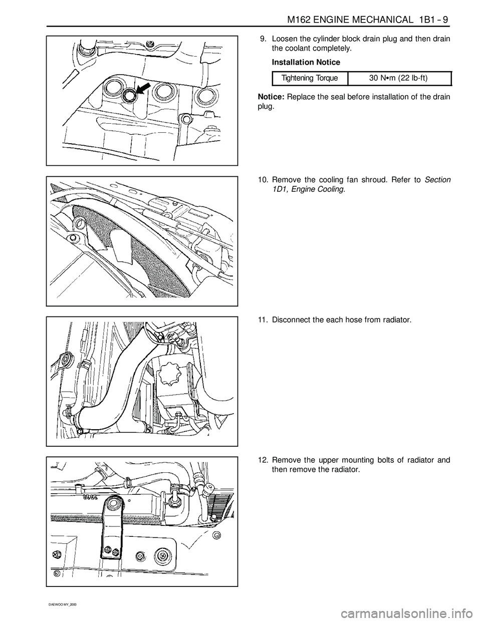
9. Loosen the cylinder block drain plug and then drain
the coolant completely.
Installation Notice
Tightening Torque
30 NSm (22 lb-ft)
Notice:Replace the seal before installation of the drain
plug.
10. Remove the cooling fan shroud. Refer toSection
1D1, Engine Cooling.
11. Disconnect the each hose from radiator.
12. Remove the upper mounting bolts of radiator and
then remove the radiator.
Page 42 of 2053

1B1 -- 10 M162 ENGINE MECHANICAL
D AEW OO M Y_2000
13. Remove the hydraulic pipe of power steering.
Notice:Completely drain the oil.
14. Discharge the refrigerant from A/C system, and dis-
connect the discharge pipe and suction pipe from
the compressor. Refer toSection 7B, Manual Con-
trol Heating, Ventilation, and Air Conditioning Sys -
tem.
15. Remove the fuel feed and return line.
Notice:Before removing the fuel lines, release the pres-
sure in the fuel system.
Installation Notice
Tightening Torque
21 -- 25 NSm (15 -- 18 lb-ft)
16. Disconnect the terminals from the generator.
Page 44 of 2053
1B1 -- 12 M162 ENGINE MECHANICAL
D AEW OO M Y_2000
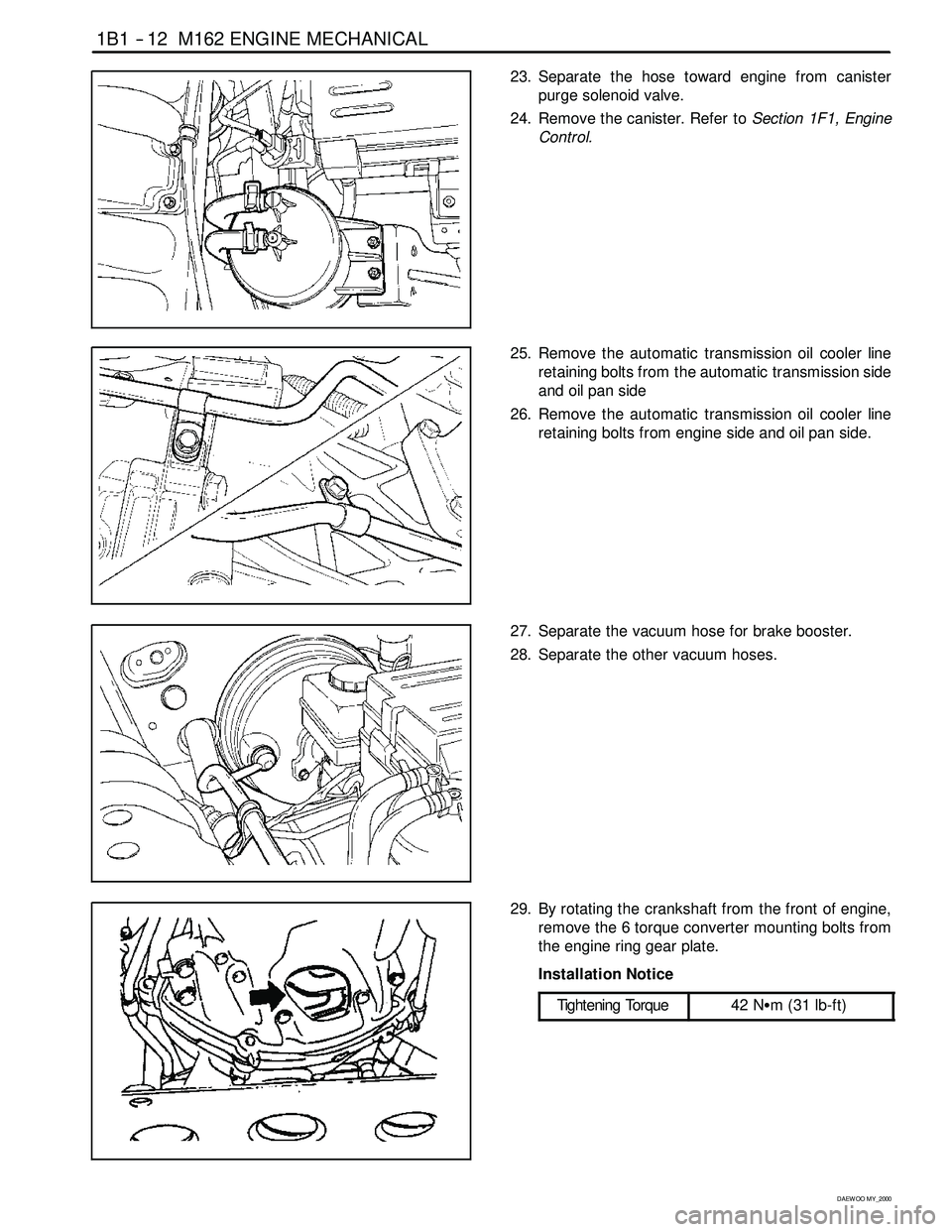
23. Separate the hose toward engine from canister
purge solenoid valve.
24. Remove the canister. Refer toSection 1F1, Engine
Control.
25. Remove the automatic transmission oil cooler line
retaining bolts from the automatic transmission side
and oil pan side
26. Remove the automatic transmission oil cooler line
retaining bolts from engine side and oil pan side.
27. Separate the vacuum hose for brake booster.
28. Separate the other vacuum hoses.
29. By rotating the crankshaft from the front of engine,
remove the 6 torque converter mounting bolts from
the engine ring gear plate.
Installation Notice
Tightening Torque
42 NSm (31 lb-ft)
Page 45 of 2053

M162 ENGINE MECHANICAL 1B1 -- 13
D AEW OO M Y_2000
30. Remove the exhaust manifold and exhaust pipe.
Installation Notice
Tightening Torque
30 NSm (22 lb-ft)
31. Remove the transmission.Refer to Section 5A, Au-
tomatic Transmission.
32. Install a chain to the bracket of engine, by using a
hoist or crane.
33. Remove the engine mount nuts.
Installation Notice
Tightening Torque
70 NSm (52 lb-ft)
34. Carefully separate the engine assembly from the ve-
hicle.
35. Installation should follow the removal procedure in
the reverse order.
Page 55 of 2053

M162 ENGINE MECHANICAL 1B1 -- 23
D AEW OO M Y_2000
8. Splits across the rib.
9. Sections of rib torn out.
10. Splits across several ribs.
11. Splits across the back of the belt.