ECU SSANGYONG KORANDO 2013 Manual PDF
[x] Cancel search | Manufacturer: SSANGYONG, Model Year: 2013, Model line: KORANDO, Model: SSANGYONG KORANDO 2013Pages: 1336, PDF Size: 92.18 MB
Page 610 of 1336

1. LAYOUT
D20DTF(Low CO2) D20DTF
ECUBattery sensor (EBS)
Alternator (ALT)
Meter cluster (charge
warning lamp)
Page 611 of 1336

0000-00
2. OPERATING PROCESS
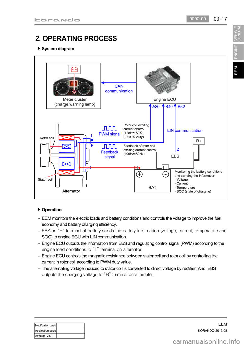
System diagram
Operation
EEM monitors the electric loads and battery conditions and controls the voltage to improve the fuel
economy and battery charging efficiency.
SOC) to engine ECU with LIN communication.
Engine ECU outputs the information from EBS and regulating control signal (PWM) according to the
Engine ECU controls the magnetic resistance between stator coil and rotor coil by controlling the
current in rotor coil according to PWM duty value.
The alternating voltage induced to stator coil is converted to direct voltage by rectifier. And, EBS
-
-
-
-
-
Page 612 of 1336

Operation of charge warning lamp
ECU checks the generating voltage from alternator and circuit conditions and sends the warning lamp ON
signal to meter cluster through CAN line.Basic control logic according to the driving conditions
Engine ECU determines the engine loads according to the fuel injection volume and engine speed. It
charges the battery by increasing the generating voltage during deceleration. To improve the fuel
economy by reducing the alternator load during acceleration, engine ECU decreases the generating
voltage and consumes the battery voltage.
Page 613 of 1336

0000-00
3. CAN COMMUNICATION (Charge Warning Lamp)
Overview
Meter cluster
(charge warning lamp)
The meter cluster receives the charge warning lamp ON signal from ECU through CAN line.
Charge warning lamp ON conditions
Pre-warning
When DTC related EEM set
Open or short circuit in alternator -
-
-
Circuit diagram
Page 630 of 1336

Make sure a connector is connected
securely. Loose connection results in
malfunction. -
When disconnecting a connector equipped with
a lock, press it down to the direction in the below
figure. -
When checking voltage or continuity of the
connector terminal with a circuit tester, connect
the tester probe to the terminal at the harness
side. For a sealed type connector, connect the
probe to the terminal through the hole in the
rubber cap of the wiring. Take care not to
damage the insulation of the wires. Insert the
probe until it contacts the terminal completely. -
When inspecting the airbag system, make sure to use a diagnostic device, not a circuit tester.
Page 631 of 1336

8410-00
2. CHECKING CABLES AND WIRES
Check for loose connection or rust.
Check terminals and wires for corrosion due to electrolyte leakage.
Check terminals and wires for open circuit.
Check the wire insulation and coat for damage, cracks or deterioration.
Check if the conductive parts of the terminals do not contact with vehicle body or other metal parts.
Check that the grounding part has continuity with mounting bolts and vehicle body.
Check that wires are properly routed.
Make sure that wires are securely fixed to avoid contact with sharp body parts and high-temperature
parts, such as the exhaust manifold and exhaust pipes.
The rotating parts, such as fan pulley and fan belt, perturbative parts and wiring should be secured
tightly at regular intervals.
Secure the wiring between the fixed parts, such as the vehicle body, and vibrating parts, such as the
engine, after slackening it slightly to prevent it from being damaged. -
-
-
-
-
-
-
-
-
-
Page 641 of 1336

8710-01
4. WITH SKM VS. WITHOUT SKM
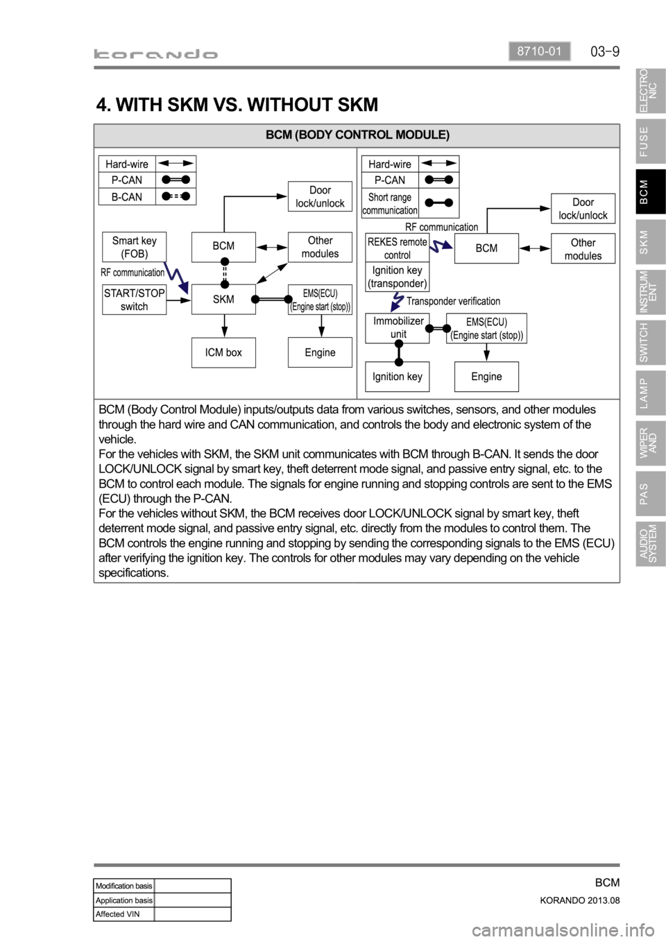
BCM (BODY CONTROL MODULE)
BCM (Body Control Module) inputs/outputs data from various switches, sensors, and other modules
through the hard wire and CAN communication, and controls the body and electronic system of the
vehicle.
For the vehicles with SKM, the SKM unit communicates with BCM through B-CAN. It sends the door
LOCK/UNLOCK signal by smart key, theft deterrent mode signal, and passive entry signal, etc. to the
BCM to control each module. The signals for engine running and stopping controls are sent to the EMS
(ECU) through the P-CAN.
For the vehicles without SKM, the BCM receives door LOCK/UNLOCK signal by smart key, theft
deterrent mode signal, and passive entry signal, etc. directly from the modules to control them. The
BCM controls the engine running and stopping by sending the corresponding signals to the EMS (ECU)
after verifying the ignition key. The controls for other modules may vary depending on the vehicle
specifications.
Page 657 of 1336

8710-01
Operating process
BCM and rain sensor system diagram
Data recognition time
The LIN communication is established when the ignition is turned ON, regardless of the wiper and light
switch operation. Then the function for the LIN data is carried out with the wiper AUTO switch or AUTO
light switch in the AUTO position.
The data from the rain sensor is recognized as 2 consecutive data.
Operation when data is recognized
Data OFF: Lo/HI relay output OFF
Low speed signal: LO relay output ON (ON for at least 1 revolution), HI relay output OFF
High speed signal: HI relay output ON (ON for at least 1 revolution), LO relay output ON
The washer input is overridden during continuous operation of wiper. (washer coupled wiper operation
during intermittent operation)
Page 720 of 1336

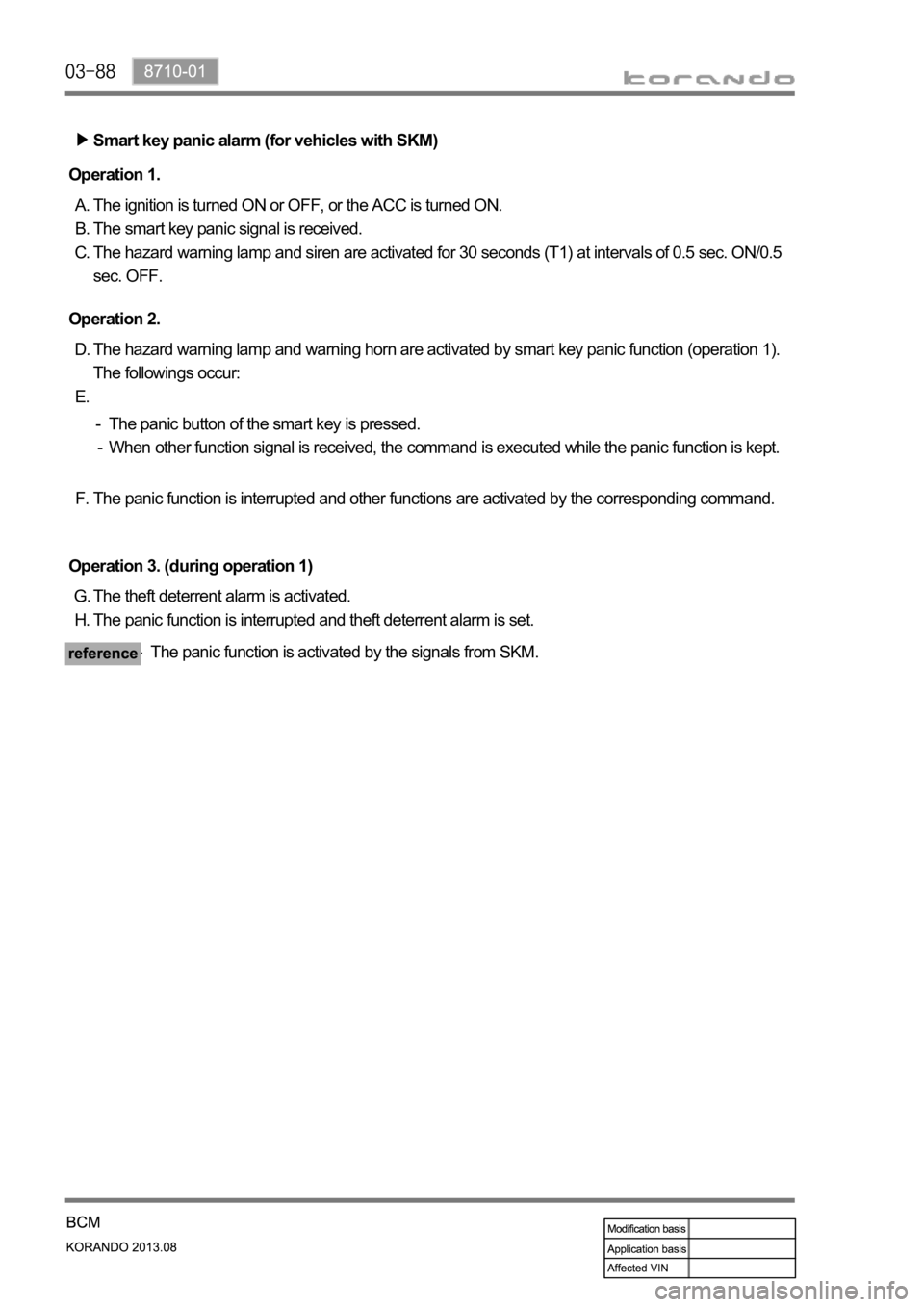
Smart key panic alarm (for vehicles with SKM)
The ignition is turned ON or OFF, or the ACC is turned ON.
The smart key panic signal is received.
The hazard warning lamp and siren are activated for 30 seconds (T1) at intervals of 0.5 sec. ON/0.5
sec. OFF. A.
B.
C. Operation 1.
The theft deterrent alarm is activated.
The panic function is interrupted and theft deterrent alarm is set. G.
H. Operation 3. (during operation 1)
The panic function is activated by the signals from SKM. - The hazard warning lamp and warning horn are activated by smart key panic function (operation 1).
The followings occur: D.
E. Operation 2.
The panic button of the smart key is pressed.
When other function signal is received, the command is executed while the panic function is kept. -
-
The panic function is interrupted and other functions are activated by the corresponding command. F.
Page 751 of 1336

8710-01
24. IMMOBILIZER SYSTEM
1) System Description
The BCM without SKM communicates with the transponder in the REKES key and immobilizer unit in
the key box through wireless communication. The immobilizer unit and BCM check the encrypted codes
received through hard wire communication to start the engine.
Stays on: Communication failure between immobilizer and EMS (ECU)
Flashes: Immobilizer coding failure (once per second)
2) System Diagram