SSANGYONG KORANDO 2013 Workshop Manual
KORANDO 2013
SSANGYONG
SSANGYONG
https://www.carmanualsonline.info/img/67/57503/w960_57503-0.png
SSANGYONG KORANDO 2013 Workshop Manual
Page 411 of 1336
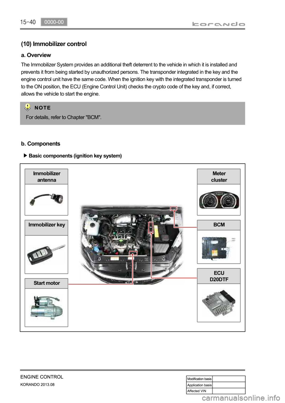
Meter
clusterImmobilizer
antenna
Immobilizer key
Start motor
BCM
ECU
D20DTF
(10) Immobilizer control
a. Overview
The Immobilizer System provides an additional theft deterrent to the vehicle in which it is installed and
prevents it from being started by unauthorized persons. The transponder integrated in the key and the
engine control unit have the same code. When the ignition key with the integrated transponder is turned
to the ON position, the ECU (Engine Control Unit) checks the crypto code of the key and, if correct,
allows the vehicle to start the engine.
For details, refer to Chapter "BCM".
b. Components
Basic components (ignition key system)
Page 412 of 1336
0000-00
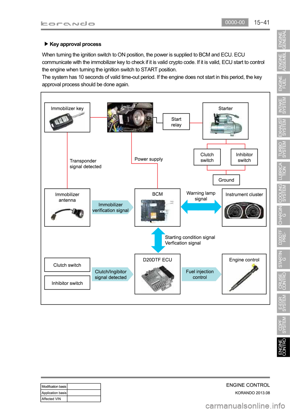
Key approval process
When turning the ignition switch to ON position, the power is supplied to BCM and ECU. ECU
communicate with the immobilizer key to check if it is valid crypto code. If it is valid, ECU start to control
the engine when turning the ignition switch to START position.
The system has 10 seconds of valid time-out period. If the engine does not start in this period, the key
approval process should be done again.
Page 413 of 1336
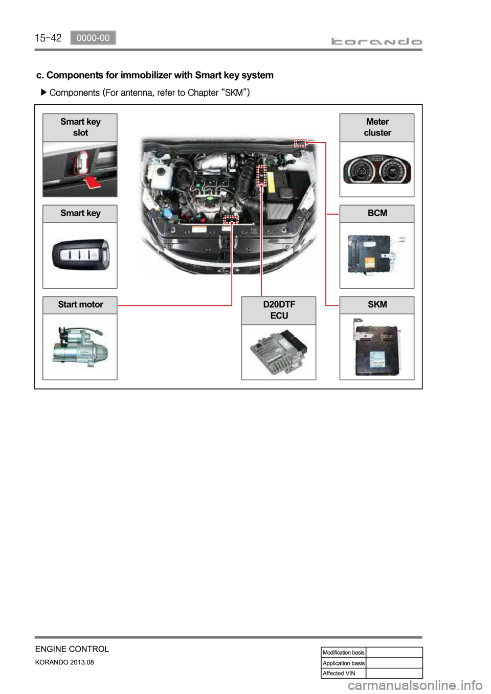
Smart key
slot
Smart key
Start motor
Meter
cluster
BCM
SKMD20DTF
ECU
c. Components for immobilizer with Smart key system
Page 414 of 1336
0000-00
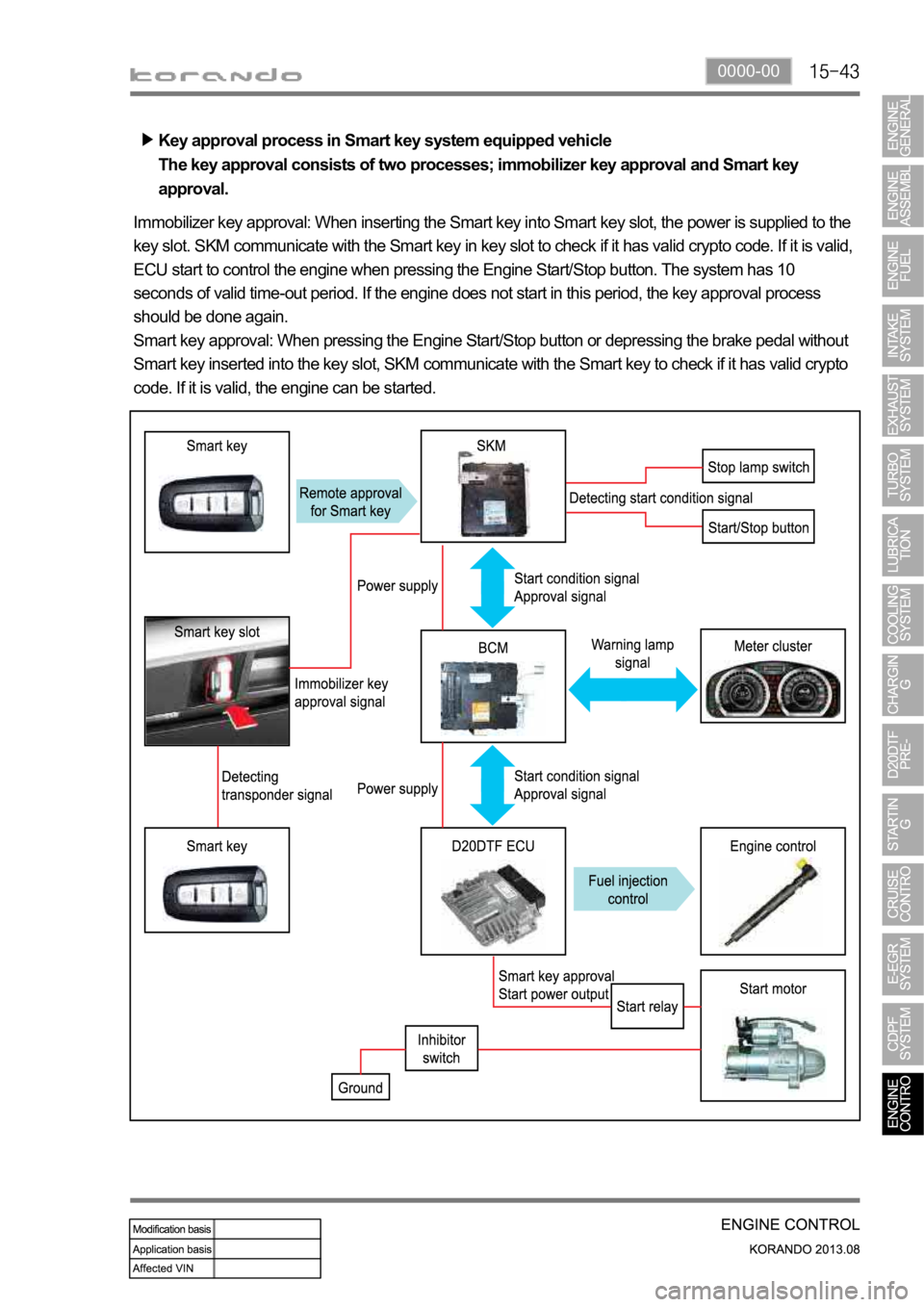
Key approval process in Smart key system equipped vehicle
The key approval consists of two processes; immobilizer key approval and Smart key
approval.
Immobilizer key approval: When inserting the Smart key into Smart key slot, the power is supplied to the
key slot. SKM communicate with the Smart key in key slot to check if it has valid crypto code. If it is valid,
ECU start to control the engine when pressing the Engine Start/Stop button. The system has 10
seconds of valid time-out period. If the engine does not start in this period, the key approval process
should be done again.
Smart key approval: When pressing the Engine Start/Stop button or depressing the brake pedal without
Smart key inserted into the key slot, SKM communicate with the Smart key to check if it has valid crypto
code. If it is valid, the engine can be started.
Page 415 of 1336
Rear temp.
sensor
Front temp.
sensorCDPF (DOC+DPF)
Throttle valveD20DTF ECUDifferential pres.
sensor
Oxygen sensor
(11) CDPF control
a. Overview
As the solution for environmental regulations and PM Particle Material) of diesel engine, the low emission
vehicle is getting popular. This vehicle is equipped with an extra filter to collect the soot and burn it again
so that the amount of PM in the exhaust gas passed through the DOC (Diesel Oxidation Catalyst) is
reduced. The CDPF (Catalyst & Diesel Particulate Filter) is an integrated filter including DOC (Diesel
Oxidation Catalyst) and DPF (Diesel Particulate Filter).
For details, refer to Chapter "CDPF".
b. Components
Page 417 of 1336

Rear temp. sensor:
Measure DPF
temp.DPF performs
recycling
(combustion)
process at 600C,
and rear
temperature sensor
monitors the
temperature of DPF.
Differential pressure
sensor measures the
pressure difference
between pre-CDPF
and post-CDPF (If
PM has been
accumulated, the
measured value is
over the specified
value).Diff. pres. sensor:
Measure
pressure between
front side and
rear side of CDPF
Injector: Control
post injection
Front temp.
sensor: Measure
DOC temp.DOC performs
oxidation and
reduction process at
front temperature
sensor monitors the
temperature of
DOC.
Electronic
throttle body:
Control intake ai
r
mass
ECU (DCM 3.7)
d. Operation process
When the differential pressure sensor detects the pressure difference between the front and the rear
side of CDPF, the sensor sends signal indicating the soot is accumulated and the post injection is
performed to raise the temperature of exhaust gas. The amount of fuel injected is determined according
to the temperature of exhaust gas detected by the rear temperature sensor. If the temperature is below
low load range, the amount of post injection and the amount of intake air are controlled. It is to raise the
temperature by increasing the amount of fuel while decreasing the amount of intake air.
T-MAP sensor
Intake air
mass
Exceed PM
limitBooster
pressure/
temperaturePost injection
Control intake air
mass
Page 419 of 1336
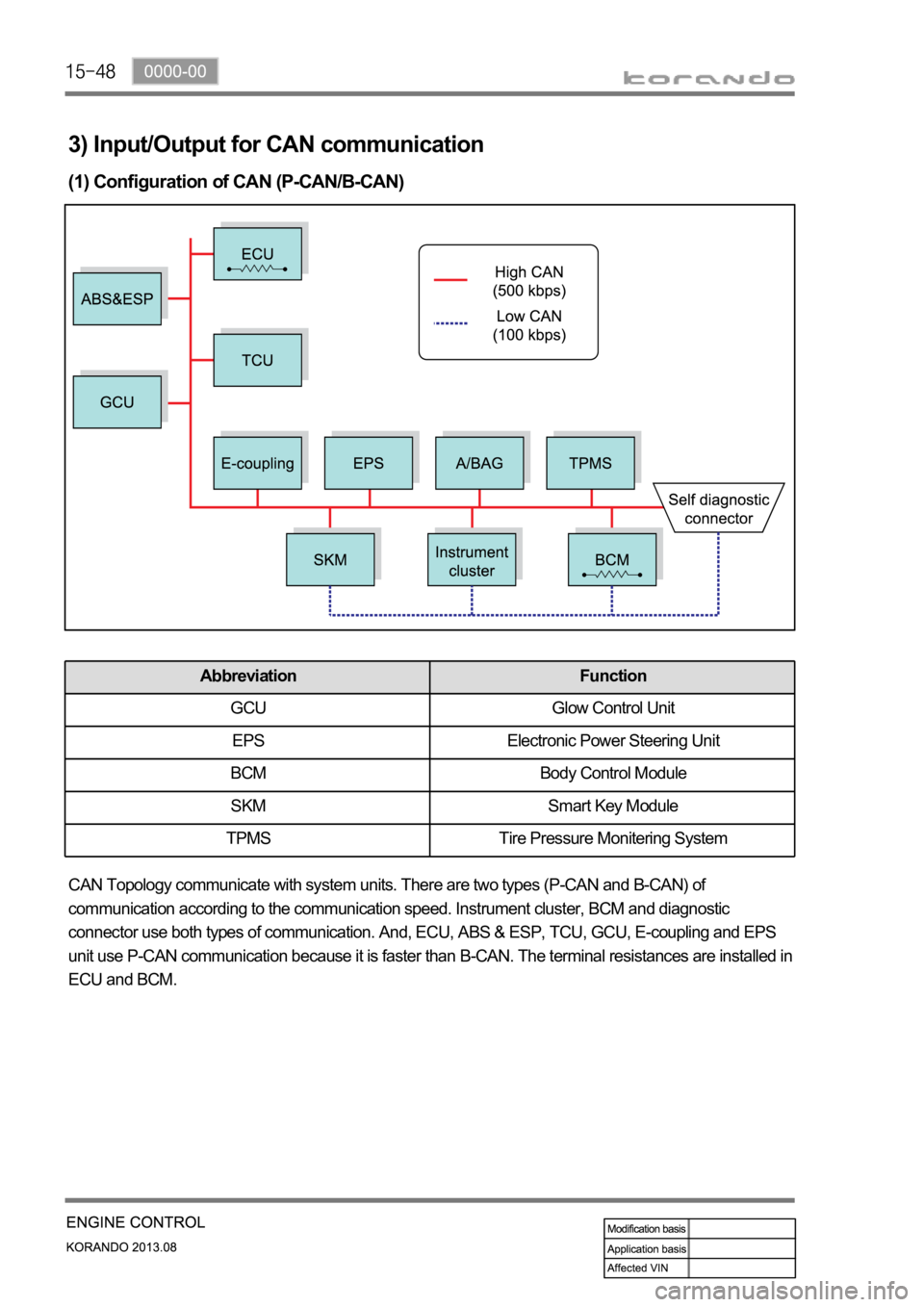
3) Input/Output for CAN communication
(1) Configuration of CAN (P-CAN/B-CAN)
CAN Topology communicate with system units. There are two types (P-CAN and B-CAN) of
communication according to the communication speed. Instrument cluster, BCM and diagnostic
connector use both types of communication. And, ECU, ABS & ESP, TCU, GCU, E-coupling and EPS
unit use P-CAN communication because it is faster than B-CAN. The terminal resistances are installed in
ECU and BCM.
Abbreviation Function
GCU Glow Control Unit
EPS Electronic Power Steering Unit
BCM Body Control Module
SKM Smart Key Module
TPMS Tire Pressure Monitering System
Page 483 of 1336
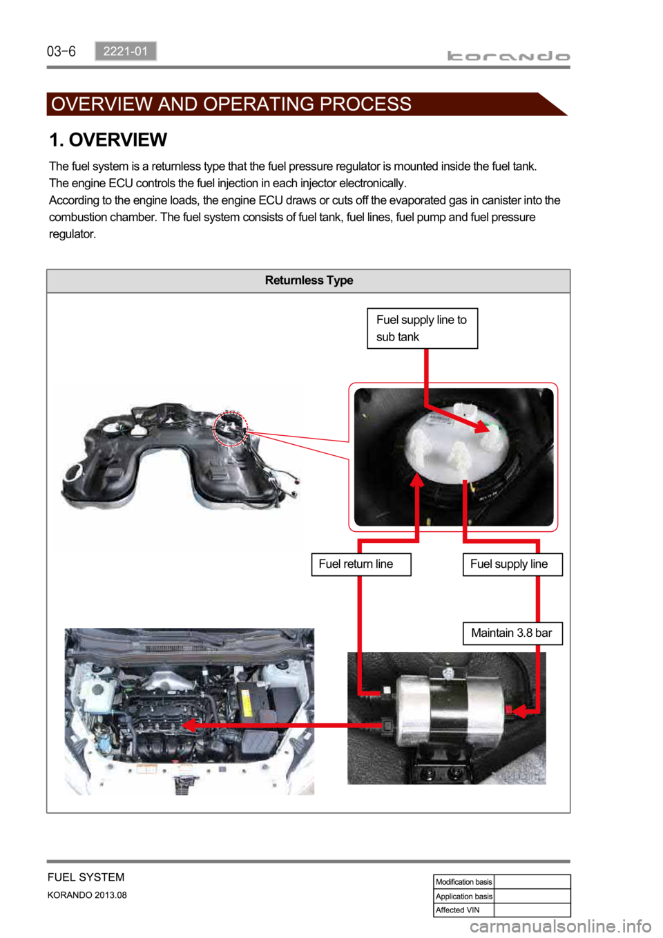
Returnless Type
1. OVERVIEW
The fuel system is a returnless type that the fuel pressure regulator is mounted inside the fuel tank.
The engine ECU controls the fuel injection in each injector electronically.
According to the engine loads, the engine ECU draws or cuts off the evaporated gas in canister into the
combustion chamber. The fuel system consists of fuel tank, fuel lines, fuel pump and fuel pressure
regulator.
Fuel supply line to
sub tank
Fuel return lineFuel supply line
Maintain 3.8 bar
Page 486 of 1336
2221-01
Engine ECU
Engine compartment
InjectorPurge control solenoid
valveFuel rail
Secondary fuel sender
Page 488 of 1336
2221-01
4. INPUT/OUTPUT DEVICES
The engine ECU calculates the accelerator pedal based on the input signals from various sensors, and
controls the overall operation of the vehicle.
The ECU receives the signals from various sensor through data line, and performs effective airfuel ratio
control based on these signals.
