SSANGYONG MUSSO 1998 Workshop Owners Manual
MUSSO 1998
SSANGYONG
SSANGYONG
https://www.carmanualsonline.info/img/67/57510/w960_57510-0.png
SSANGYONG MUSSO 1998 Workshop Owners Manual
Trending: alternator belt, glow, bonnet, oil, spark plugs replace, engine oil capacity, charging
Page 91 of 1463
1B1-18 M162 ENGINE MECHANICAL
ALTERNATOR
1 Nut (M8).........................................22.5-27.5 Nm
2 Bolt (M8 x 30, 3 pieces).................22.5-27.5 Nm
3 Bolt (M8 x 40, 1 piece)...................22.5-27.5 Nm
Removal & Installation Procedure
1. Remove the drive belt.
2. Remove the alternator.
3. Unscrew the alternator carrier bolts and remove the carrier.
Installation Notice4 Bolt (M8 x 70, 1 piece)...................22.5-27.5 Nm
5 Bolt (M8 x 75, 1 piece)...................22.5-27.5 Nm
Tightening Torque 10 - 15 Nm
4. Installation should follow the removal procedure in the
reverse order.
Page 92 of 1463
M162 ENGINE MECHANICAL 1B1-19
POWER STEERING PUMP AND A/C BRACKET
Preceding Work : Removal of cooling fan and shroud
1 Vent Hose
2 Bolt (M8 x 91, 2 pieces).................22.5-27.5 Nm
3 Power Steering Pump
4 Bolt (M8 x 105, 4 pieces)...............22.5-27.5 Nm
5 Washer
6 A/C Compressor
7 Bolt (M8 x 40, 3 pieces,
M8 x 95, 2 pieces)..........................22.5-27.5 Nm8 A/C Bracket
9 Gasket ................................................... Replace
10 Bracket
11 Bolt (M8 x 22, 2 pieces).................22.5-27.5 Nm
12 Tensioning Pulley
13 Nut .................................................40.5-49.5 Nm
Page 93 of 1463
1B1-20 M162 ENGINE MECHANICAL
Removal & Installation Procedure
1. Remove the belt pulley.
Installation Notice
2. Disconnect the hydraulic pipe of the power steering pump
and drain the oil.
3. Unscrew the bolts (arrows) and remove the steering pump.
Installation Notice Notice
Pull the tensioning pulley clockwise as shown in the figure.
4. Remove the compressor after disconnecting the wiring
connector and refrigerant pipe of A/C compressor.
Notice
Discharge all the refrigerant before removing the pipes.
Tightening Torque 40.5 - 49.5 Nm
Tightening Torque 22.5 - 27.5 Nm
Page 94 of 1463
M162 ENGINE MECHANICAL 1B1-21
5. Disconnect the vent hose from the A/C bracket.
6. Unscrew all the mounting bolts (arrows) and remove the
A/C bracket and the gasket.
Installation Notice
7. Clean the sealing surface.
8. Replace the gasket with new one.
9. Installation should follow the removal procedure in the
reverse order.
10. Check the oil leakage by operating the engine after
installation.
Tightening Torque 22.5 - 27.5 Nm
Page 95 of 1463
1B1-22 M162 ENGINE MECHANICAL
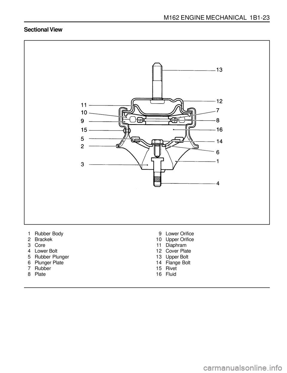
HYDRAULIC ENGINE MOUNTING INSULATOR
Service Data
Page 96 of 1463
M162 ENGINE MECHANICAL 1B1-23
Sectional View
1 Rubber Body
2 Brackek
3 Core
4 Lower Bolt
5 Rubber Plunger
6 Plunger Plate
7 Rubber
8 Plate9 Lower Orifice
10 Upper Orifice
11 Diaphram
12 Cover Plate
13 Upper Bolt
14 Flange Bolt
15 Rivet
16 Fluid
Page 97 of 1463
1B1-24 M162 ENGINE MECHANICAL
1 Upper Nut
2 Hydraulic Installor.................62-93 Nm
3 Lower Nut.............................28-47 Nm
Removal and Installation Procedure
1. Unscrew the upper nut(1) on engine mounting and remove
the engine.
Installation Notice
3. Installation should follow the removal procedure in the
reverse order.
Tightening Torque 62 - 93 Nm
2. Unscrew the lower nut(3) and remove the hydraulic engine
mounting insulator.
Installation Notice
Tightening Torque 28 - 47 Nm
Notice
If the insulator is spotted with oil, replace the hydraulic
insulator assembly.
Page 98 of 1463
M162 ENGINE MECHANICAL 1B1-25
POLY V - BELT
Preceding Work : Removal of cooling fan
1 Poly V-belt
Removal & Installation Procedure
1. Release the belt tension by turning the belt tensioning pulley
nut clockwise.
2. Remove the poly v-belt.
Notice
Check the belt for damage and tensioning pulley bearing
point for wear and replace them if necessary.
3. Install the belt by turning the nut of tensioning pulley
clockwise.
2 Belt Tensioning Pulley
Page 99 of 1463
1B1-26 M162 ENGINE MECHANICAL
Poly V-Belt Arrangement
1 Belt Tensioning Pulley
2 Crankshaft Belt Pulley
3 A/C Compressor Pulley
4 Cooling Fan Pulley5 Alternator Pulley
6 Idler
7 Power Steering Pump Pulley
8 Cooling Fan and Water Pump Pulley
Page 100 of 1463
M162 ENGINE MECHANICAL 1B1-27
TENSIONING DEVICE
Preceding Work : Removal of poly v-belt
1 Belt (L = 2245)
2 Bolt Combi(M8 x 14, 3 pieces) + Washer
.......................................................22.5-27.5Nm
Removal & Installation Procedure
1. Remove the poly v-belt.
2. Remove the tensioning pulley by turning its mounting nut
counter clockwise as shown in figure.
Installation Notice3 Water Pump Pulley
4 Nut
5 Tensioning Pulley
Tightening Torque 40.5 - 49.5 Nm
Trending: run flat, compression ratio, clutch, service indicator, fuses, airbag, parking brake


