lock SSANGYONG MUSSO 1998 Workshop Repair Manual
[x] Cancel search | Manufacturer: SSANGYONG, Model Year: 1998, Model line: MUSSO, Model: SSANGYONG MUSSO 1998Pages: 1463, PDF Size: 19.88 MB
Page 1204 of 1463

5D1-34 TRANSFER CASE (PART TIME 4408)
External Electric Shift
1. Align the motor with shift shaft and position the motor
assembly onto the cover.
2. Install the motor to the shift shaft and contact cover androtate
the motor clockwise direction to check correctengagement.
6 Bolt
7 Washer
8 Bolt
9 Sensor and Harness Bracket
10 Sensor Assembly
14 Speed Sensor
12 O-ring
13 Motor Assembly
25 Cover
13 Motor Assembly
103 Shift Shaft
3. Insert the 0-ring on the speed sensor speed sensor
assembly to the cover.
4. Install the bracket to the motor assembly and tighten 3bolts.
Tightening Torque 8 -11 Nm
Page 1207 of 1463

TRANSFER CASE (PART TIME 4408) 5D1-37
Inspection and Repair
1. 4H and 4L indicator light inspection
lWhen turn the ignition switch to "ON" position, 4H and
4L indicator light will turn on for 0.6 second and will turn
off immediately.
Notice
If indicator light does not turn on, check bulb, wiring harness
and TCCU.
2. TCCU inspection
Pin No.
Operation Condition
4H or 4L
2H
4H indicator light ON
4H indicator light OFF
2H or 4H
4L
Clutch pedal applied
Clutch pedal released
4L indicator light ON
4L indicator light OFF
Motor OFF
Motor ON
Motor OFF
Motor ON
Auto locking hub ON
Auto locking hub OFFVoltage(V)
4.75 - 5.35
0 - 0.50
< 1.00
> 11.00
4.75 - 5.35
0 - 0.50
< 0.50
> 11.00
< 1.00
> 11.00
< 1.00
> 11.00
< 1.00
> 11.00
> 11.00
< 1.00 J1 - 7
J1 - 8
J1 - 13
J1 - 14
J1 - 15
J1 - 16
J1 - 17
J1 - 23
Notice
lDC 12V for the TCCU operation should be maintained.
lIn case of J1-8 and J1-15, indicator light will turn on for 0.6
second when turn the ignition switch ON.
lIf 4H and 4L indicator lights remain turned on when turn the
ignition switch on or during driving, perform the TCCU
diagnosis.
Page 1211 of 1463

5D2-4 TRANSFER CASE (TOD)
FUNCTION DESCRIPTION
lTOD System Select Mode (4H and 4L)
4H is the mode when drive normally of which gear ratio is 1:1 and 4L mode distributes power to front and rear
wheels 50:50 of which gear ratio is 2.48:1.
lTOD System Function (select 4H mode)
TOD system controls clutch mechanism to comply with rotation in front and rear propeller shaft and if its difference
exceeds the permissible range, corresponding power is distributed into front wheel through EMC (Electro-Magnetic
Clutch).
Hall effect sensor signals speed on front and rear propeller shafts going through with TOD control unit.
Transfercase clutch coil is activated by variable current on exceeding difference of speed in front and rear propeller
shafts.
lFunction of 4L Mode
When select 4L mode, EMC is locked to apply maximum torque into front and rear propeller shafts. Shift motor
rotates also 4L position by rotation of cam thus propeller shaft torque changes from 1:1 to 2.48:1 by planetary
gear set.
lShift Motor
It locates backside transfer case, which drives rotary helical cam.
When mode select switch changes to 4L, shift fork is on position for 2.48:1 by rotation of helical cam.
lTransfer Case
TOD transfer case distributes power into front and rear axle by operation of 4H/4L switch and shift motor.
Shifting 4H to 4L, is performed towards reducing HI-LO collar by means for connection HI-LO shift fork with
output shaft in order to join with planetary gear. Torque transmits input shaft then sun gear rotating front planetary
gear. Front planetary gear join with output shaft and drives LO position.
Page 1212 of 1463

TRANSFER CASE (TOD) 5D2-5
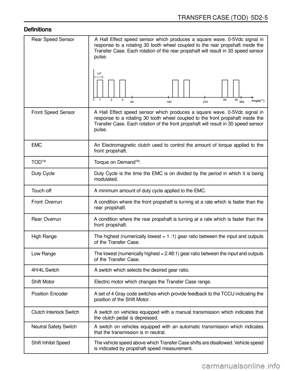
Definitions
Rear Speed Sensor A Hall Effect speed sensor which produces a square wave. 0-5Vdc signal in
response to a rotating 30 tooth wheel coupled to the rear propshaft inside the
Transfer Case. Each rotation of the rear propshaft will result in 30 speed sensor
pulse.
Front Speed SensorA Hall Effect speed sensor which produces a square wave. 0-5Vdc signal in
response to a rotating 30 tooth wheel coupled to the front propshaft inside the
Transfer Case. Each rotation of the front propshaft will result in 30 speed sensor
pulse.
EMC An Electromagnetic clutch used to control the amount of torque applied to the
front propshaft.
TOD
TMTorque on DemandTM.
Duty Cycle Duty Cycle is the time the EMC is on divided by the period in which it is being
modulated.
Touch-off A minimum amount of duty cycle applied to the EMC.
Front OverrunA condition where the front propshaft is turning at a rate which is faster than the
rear propshaft.
Rear Overrun A condition where the rear propshaft is turning at a rate which is faster than the
front propshaft.
High RangeThe highest (numerically lowest = 1 :1) gear ratio between the input and outputs
of the Transfer Case.
Low RangeThe lowest (numerically highest = 2.48:1) gear ratio between the input and outputs
of the Transfer Case.
4H/4L Switch A switch which selects the desired gear ratio.
Shift Motor Electric motor which changes the Transfer Case range.
Position Encoder A set of 4 Gray code switches which provide feedback to the TCCU indicating the
position of the Shift Motor.
Clutch Interlock Switch A switch on vehicles equipped with a manual transmission which indicates that
the clutch pedal is depressed.
Neutral Safety Switch A switch on vehicles equipped with an automatic transmission which indicates
that the transmission is in neutral.
Shift Inhibit Speed The vehicle speed above which Transfer Case shifts are disallowed. Vehicle speed
is indicated by propshaft speed measurement.
Page 1220 of 1463

TRANSFER CASE (TOD) 5D2-13
Speed Sensor/Clutch Coil and Motor Connector
Speed senso /clutch coil and shift motor connector locate upper
backside transfer case (upper part of shift motor).
- Shift motor connector : Black
- Speed sensor and clutch coil connector : White
Shift Mtor Connector Speed Sensor/Clutch Coil Connector
Rear View for Connector
Pin
A
B
C
D
E
F
GFunction
Position 4
Motor (Counter-Clockwise)
Position 3
Position 2
Position 1
Position Retum
Motor (Clockwise)Pin
H
I
J
K
L
M
NFunction
Clutch Coil (EMC)
Front Speed Return
Front Speed
Front Speed Sensor Supply
Rear Speed Sensor Supply
Rear Speed
Rear Speed Return Rear View for Connector
Page 1221 of 1463

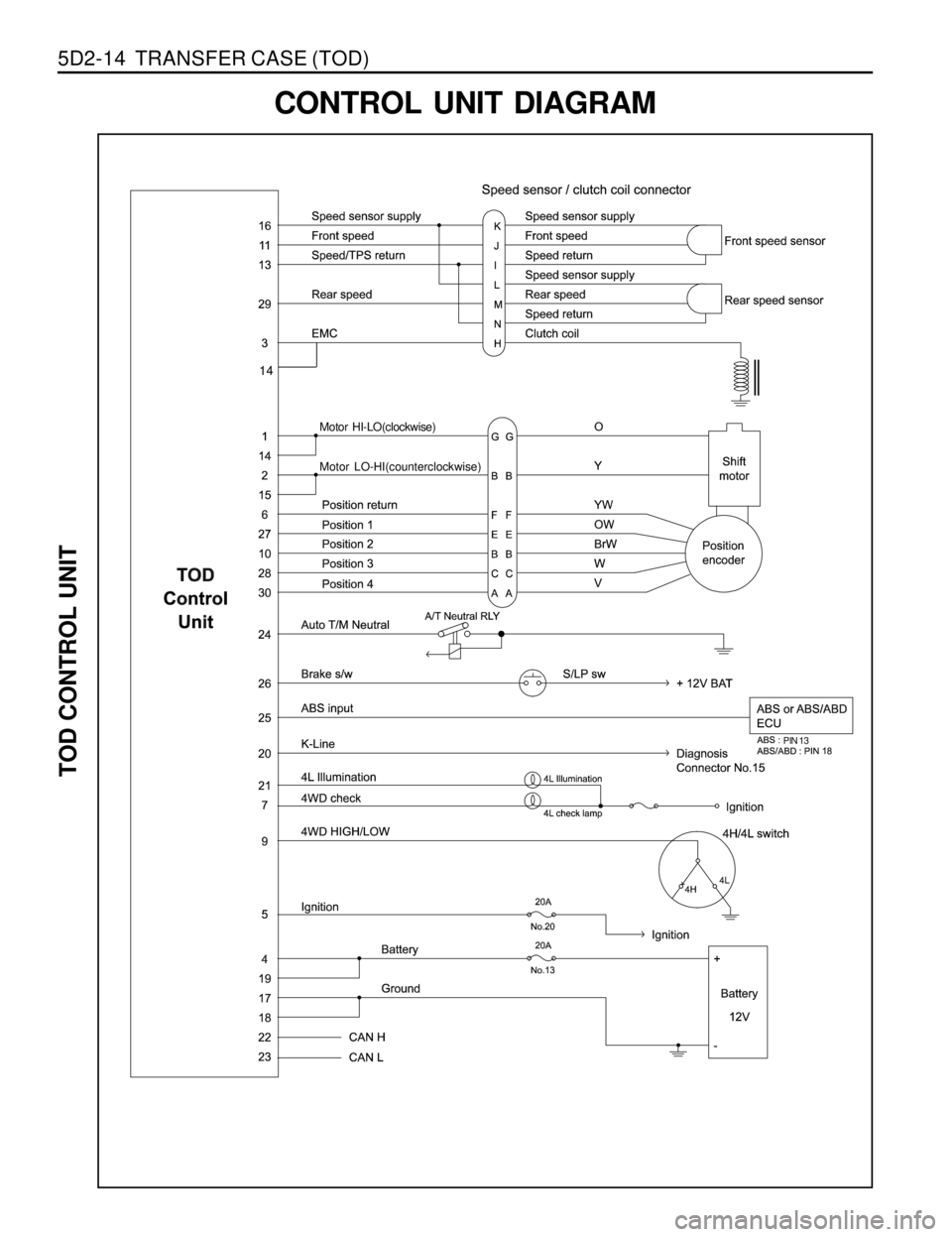
5D2-14 TRANSFER CASE (TOD)
Motor HI-LO(clockwise)
Motor LO-HI(counterclockwise)
PIN 13
CONTROL UNIT DIAGRAM
TOD CONTROL UNIT
14
Page 1242 of 1463

TRANSFER CASE (TOD) 5D2-35
Removal & Installation Procedure
1. Disconnect (-) cable from battery.
2. Lift on vehicle and make sure on safety.
Notice
Be careful for catalytic converter due to high temperature
after driving or engine running.
3. Prepare a vessel to drain transfer case and manual
transmission oil.
4. Release drain plug and drain transfer case and manual
transmission oil.
If planar damper is installed, unscrew 4 bolts and remove
the planar damper.
Notice
Oil drain should be along with whole transfer case
disassembly and assembly.
5. Disconnect transmission extension wiring connector back
side transfer case.
Notice
When disconnect connector, make sure on direction of
locking tab towards inside.
6. Disconnect shift motor/clutch coil connect (Black 7 pin)
connector upper backside.
7. Disconnect front and rear speed sensor connector (white
7 pin).
8. Disconnect speedometer sensor connector right upper
side.
9. Disconnect breather tube front upper side transfer case
(upper connecting point of transfer case and front
propeller).
10. Prepare hydraulic jack and support transfer case assembly.
Page 1245 of 1463

5D2-38 TRANSFER CASE (TOD)
SPEED SENSOR IN FRONT AND
REAR PROPELLER SHAFT
Replacement Procedure
1. Disconnect (-) cable from battery.
2. Detach shift motor assembly.
3. Disconnect front and rear speed sensor connector (white 3
pin) upper backside transfer case.
4. Disconnect speed sensor connect from locking sleeve by
pushing.
5. Disconnect wire stick cap from the detached connector.
6. Unscrew rear speed sensor mounting bolt (M10) from upper
side of rear case flange.
7. Detach sensor from transfer case by lifting up using tool.
Notice
When disconnect sensor, make sure on adequate pressure
due to sensitiveness with shock.
8. Disconnect taping from both protection tube ends that wrap
3 wires of speed sensor and 1 wire of clutch coil.
9. Disconnect tube.
Page 1246 of 1463

TRANSFER CASE (TOD) 5D2-39
10. Disconnect pin and wire from speed sensor connector by
pulling sticking long-nose plier into “L” pin in connector.
11. On the same way, disconnect pin and wire “M” and “N”
from connector.
Notice
Do not touch the wires related with EMC.
12. Prepare new speed sensor.
13. Connect 3 pins with wires of speed sensor to coincide with
each connection position.
14. Using long-nose plier, connect tightly by pulling pins.
15. Apply rubber cap into connector using long-nose plier not
to detach.
16. Connect protection tube with wire.
17. Tape both ends of tube.
18. Putting rear speed sensor into hole, connect exactly
pushing both ends.
19. Screw 1 unit of bolt (M10).
Installation Notice
Tightening Torque 9 - 11 Nm
20. Connect speed sensor connector, then locking sleeve.
Reference
Front propeller shaft should be premised by removal of
shift motor.
After disconnecting shift motor, procedure of replacement
on sensor assembly of accords with one of rear speed
sensor.
Page 1255 of 1463

5D2-48 TRANSFER CASE (TOD)
6. Install the front planet to the sun gear and input shaft.
Install the internal snap ring to the planetary carrier.
7. Place the tanged snap ring in the case. Expand snap ring
with snap ring pliers and install planetary carrier assembly.
Check installation by holding the case and carefully tapping
the face of the input shaft against a wooden block to make
sure the snap ring is installed.
8. Remove all traces of gasket sealant from the front case
and mounting adapter mating surfaces. Install a bead of
gasket sealant on the surface of the front case.
9. Install the high-low shift fork and high-low collar as an
assembly into the front planet.
Notice
Make sure that the nylon wear pads are installed on the
shift fork and snapped securely into place.
12 Rear Output Shaft
13 Oil Strainer
14 Coupling Hose
15 Hose Clamp
16 Pump Body
10. If new pump is used, align the flat of the output shaft and
the flat of the pump. Slide the pump onto the output shaft.
lDo not disassemble oil pump. It is serviced only as an
assembly. Check the pump to make sure the pump
rotates freely.
lDo not remove the plastic insert from the bore of the
new pump. Discard it after it slides out during pump
installation to the rear output shaft.
lWhile turning the output shaft, prime the pump through
the oil filter pickup tube or housing inlet hole with clean
Automatic Transmission Fluid or equivalent.
11. Inspect the outside surfaces and bore of the oil pump. If
there is no discoloration in the pump housing, gear or cover,
and the pump bore and the lube holes of the output shaft
show evidence of oil, the pump is working.