check engine SSANGYONG MUSSO 2003 Service Manual
[x] Cancel search | Manufacturer: SSANGYONG, Model Year: 2003, Model line: MUSSO, Model: SSANGYONG MUSSO 2003Pages: 1574, PDF Size: 26.41 MB
Page 564 of 1574
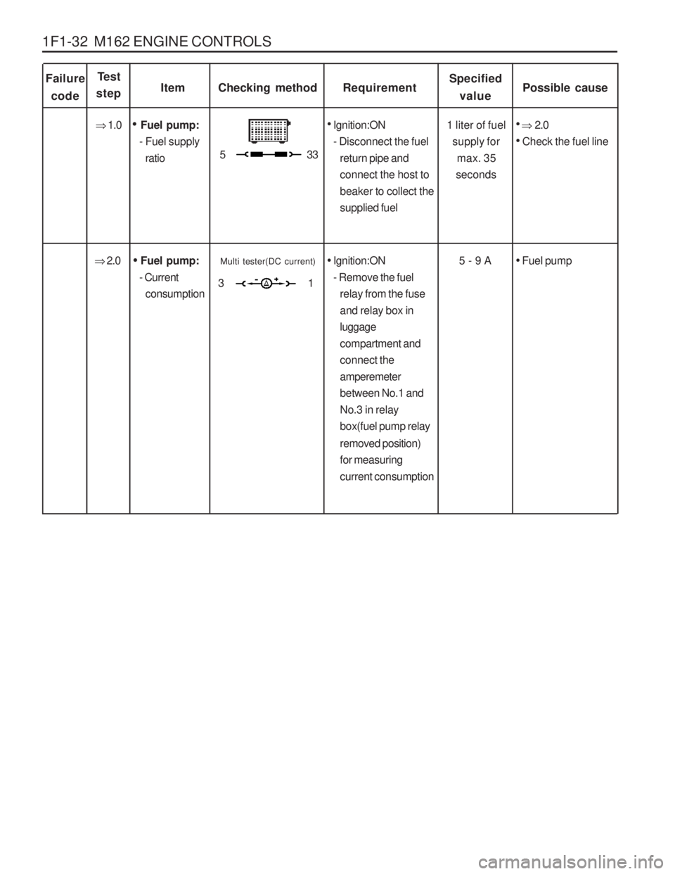
1F1-32 M162 ENGINE CONTROLS
Failurecode ItemChecking method
Test
stepRequirementSpecified
value Possible cause
1 liter of fuel supply formax. 35
seconds
Fuel pump:
- Fuel supply ratio
Ignition:ON
- Disconnect the fuel return pipe and connect the host tobeaker to collect thesupplied fuel
�
1.0
� 2.0
Check the fuel line
5 - 9 A
Fuel pump:
- Current consumption
Ignition:ON
- Remove the fuel relay from the fuseand relay box inluggagecompartment andconnect theamperemeterbetween No.1 andNo.3 in relaybox(fuel pump relay removed position) for measuringcurrent consumption
�
2.0
Fuel pump
53 3
Multi tester(DC current)
31
Page 566 of 1574

1F1-34 M162 ENGINE CONTROLS Figure 9. Shop Made CableFigure 10. Fuel Injector Normal Spary Pattern
Failure
code ItemChecking method
Test
stepRequirementSpecified value Possible cause
There should be no leaks and later
drops from
the injector
Injector:
- Leakage test
Ignition:ON
- Remove the fuel distributor and fuel injector with a unit.
�
1.0
The spray
pattern of the injector most show in the figure 10.
Ignition:ON
- Connect the shop made cable to theinjector
- Collect the spraying fuel with a beaker
- Connect the shop made cable toNo.21(+) and No.3
(-) terminal in test box
�
2.0
Injector
53 3
Injector:
- Function test and spray patterncheck
53 3
Page 579 of 1574

M162 ENGINE CONTROLS 1F1-47
3. Disconnect the vacuum hose.
4. Disconnect the circlip and remove the fuel pressureregulator.
5. Apply the oil to O-ring lightly and then replace it.
6. Installation should follow the removal procedure in the reverse order.
7. Check for fuel pressure and internal leaks by operating the engine.
2. Discharge the pressure in fuel supply system by pressing
the service valve.
Removal & Installation Procedure
1. Remove the fuel pressure test connector.
Page 583 of 1574

M162 ENGINE CONTROLS 1F1-51
Removal & Installation Procedure
1. Discharge the fuel pressure from the fuel pressure testconnector.
2. Disconnect the battery ground cable.
3. Disconnect the vacuum hose from the fuel pressure regulator.
4. Remove the cable guide.
5. Remove the fuel return and supply line.
Notice
� For removal, cover around parts with cloths not to be
stained by fuel.
� In case of checking the injector only, do not remove the
fuel return and supply line.
Installation Notice
6. Remove the six injector connectors.
7. Remove the two left and two right bolts and one center bolt of the fuel distributor assembly from the intake manifold. Installation Notice
Tightening Torque 25 - 30 Nm
Tightening Torque 22.5 - 27.5 Nm
Page 584 of 1574

1F1-52 M162 ENGINE CONTROLS8. Remove the injectors and the fuel distributor carefully.
9. Installation should follow the removal procedure in the reverse order.
10. Check for fuel pressure and internal leakage by operating the engine.
Fuel Pressure Test
1. Turn the ignition switch to "OFF" position.
2. Remove the fuel pressure test connector.
Vacuum Hose Connected (bar) 3.2 - 3.6 Vacuum Hose Disconnected (bar) 3.7 - 4.2
5. Replace the pressure regulator diaphragm if out of the specification.
3. Connect the fuel pressure gauge to the fuel pressure test
connector.
4. Test the fuel pressure at idling by operating the engine.
Page 585 of 1574

M162 ENGINE CONTROLS 1F1-53
3. If there is no change in fuel pressure and maintain thefollowing pressure over 30 minutes, it is normal.
Internal Leakage Test
1. Connect the fuel pressure gauge to the fuel pressure test
connector.
2. Stop the engine for approx. 30 minutes and then check the fuel pressure changes.
Fuel pressure
drops slowly
Fuel leakage at the injector
Faulty fuel pressureregulator'sdiaphragm and O- ring.
Fuel pressure
drops rapidly
Faulty check valve in the fuel pump.
Possible Cause
Pressure Change
Fuel Pressure(bar) 2.5
Discharging the pressure in fuel system
1. Remove the fuel pressure test connector. Installation Notice
2. Remove the fuel pressure in fuel system by pressing the service valve with a clean, pointy tool. Notice Place a cloth so that the fuel doesn't stain around.
Tightening Torque 22.5 - 27.5 Nm
Page 587 of 1574
M162 ENGINE CONTROLS 1F1-55
Removal & Installation Procedure
1. Remove the O-ring.Check for damage and replace it if necessary.
2. Remove the injector bracket from the injector.
Installation Notice Exactly seat the anti-twist lock into the square groove in
injector.
3. Separate the injector from the fuel distributor. Inspection & Maintenance Inspection of the Injector operation and spray pattern
1. Connect the contact box to the ECU.
2. Connect the shop made test plug to the injector and place it into the tank.
3. Position the ignition switch to ON.
4. Connect the pin 63(+) and 69(-) of the contact box with a test cable.
5. Check the injector spray pattern.
NoticeReplace the injector if the injector spray pattern is abnormal or the fuel doesn't inject.
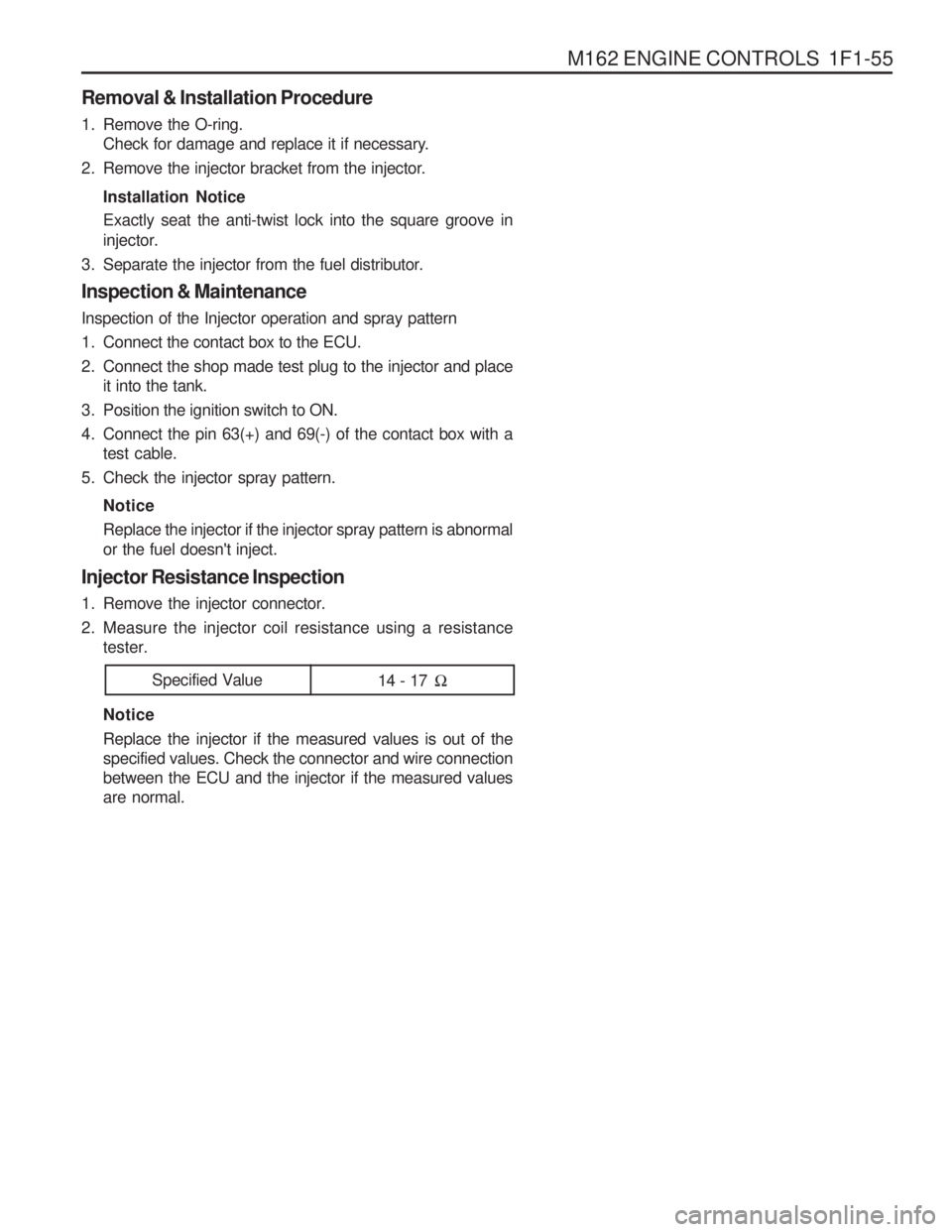
Injector Resistance Inspection
1. Remove the injector connector.
2. Measure the injector coil resistance using a resistance tester. Notice Replace the injector if the measured values is out of the specified values. Check the connector and wire connectionbetween the ECU and the injector if the measured valuesare normal.
Specified Value 14 - 17 �
Page 588 of 1574
1F1-56 M162 ENGINE CONTROLS
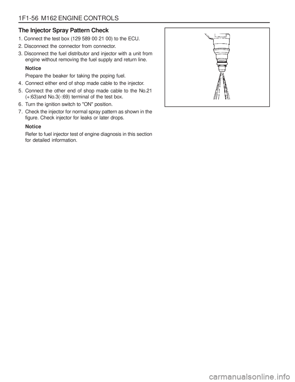
The Injector Spray Pattern Check 1. Connect the test box (129 589 00 21 00) to the ECU.
2. Disconnect the connector from connector.3. Disconnect the fuel distributor and injector with a unit fromengine without removing the fuel supply and return line. Notice Prepare the beaker for taking the poping fuel.
4. Connect either end of shop made cable to the injector.
5. Connect the other end of shop made cable to the No.21 (+:63)and No.3(-:69) terminal of the test box.
6. Turn the ignition switch to "ON" position.
7. Check the injector for normal spray pattern as shown in the figure. Check injector for leaks or later drops. Notice Refer to fuel injector test of engine diagnosis in this section for detailed information.
Page 589 of 1574
M162 ENGINE CONTROLS 1F1-57
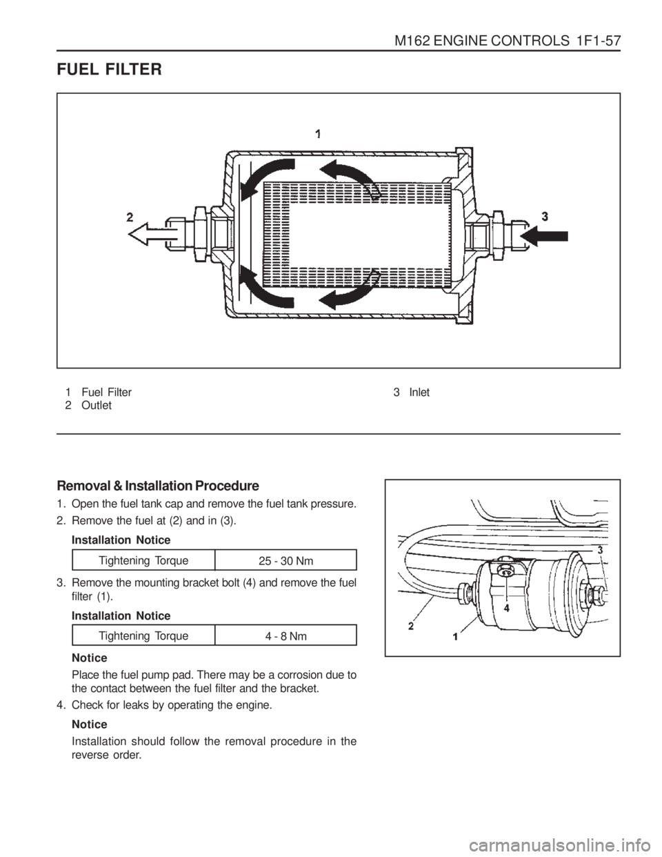
FUEL FILTER
1 Fuel Filter
2 Outlet
Removal & Installation Procedure
1. Open the fuel tank cap and remove the fuel tank pressure.
2. Remove the fuel at (2) and in (3). Installation Notice Notice Place the fuel pump pad. There may be a corrosion due to the contact between the fuel filter and the bracket.
4. Check for leaks by operating the engine.
Notice Installation should follow the removal procedure in the
reverse order.
3. Remove the mounting bracket bolt (4) and remove the fuel
filter (1). Installation Notice 3 Inlet
Tightening Torque
25 - 30 Nm
Tightening Torque 4 - 8 Nm
Page 592 of 1574
1F1-60 M162 ENGINE CONTROLS
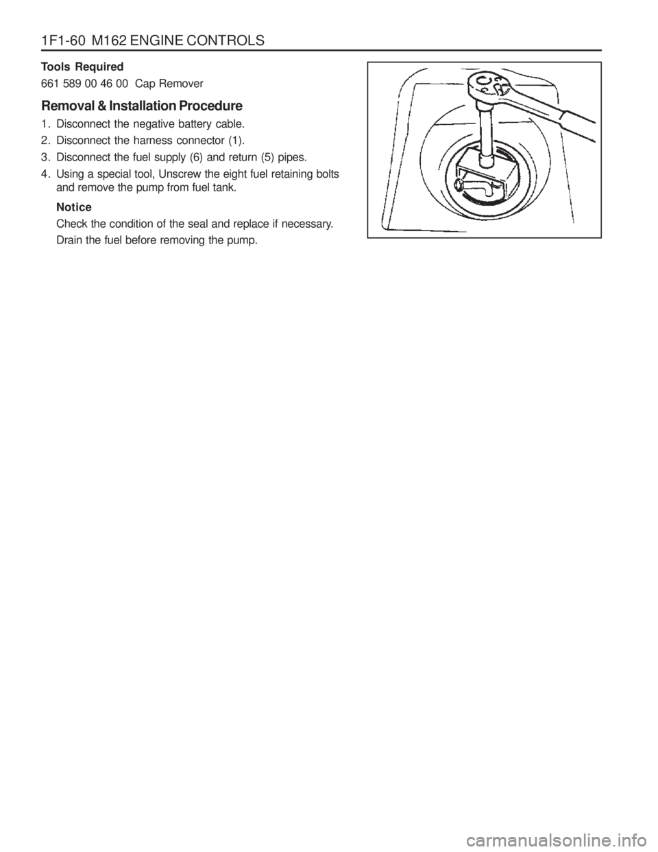
Tools Required 661 589 00 46 00 Cap Remover Removal & Installation Procedure
1. Disconnect the negative battery cable.
2. Disconnect the harness connector (1).
3. Disconnect the fuel supply (6) and return (5) pipes.
4. Using a special tool, Unscrew the eight fuel retaining boltsand remove the pump from fuel tank. Notice
Check the condition of the seal and replace if necessary. Drain the fuel before removing the pump.