check engine SSANGYONG MUSSO 2003 Service Manual
[x] Cancel search | Manufacturer: SSANGYONG, Model Year: 2003, Model line: MUSSO, Model: SSANGYONG MUSSO 2003Pages: 1574, PDF Size: 26.41 MB
Page 668 of 1574
M162 ENGINE INTAKE & EXHAUST 1G1-7
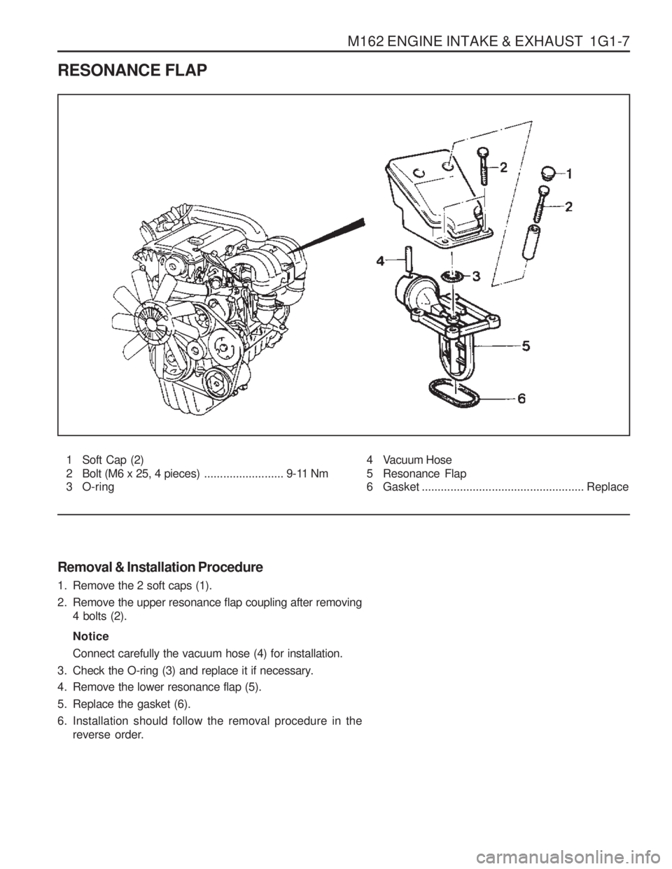
RESONANCE FLAP1 Soft Cap (2)
2 Bolt (M6 x 25, 4 pieces) ......................... 9-11 Nm
3 O-ring
Removal & Installation Procedure
1. Remove the 2 soft caps (1).
2. Remove the upper resonance flap coupling after removing
4 bolts (2). Notice Connect carefully the vacuum hose (4) for installation.
3. Check the O-ring (3) and replace it if necessary.
4. Remove the lower resonance flap (5).
5. Replace the gasket (6).
6. Installation should follow the removal procedure in the reverse order. 4 Vacuum Hose
5 Resonance Flap
6 Gasket ................................................... Replace
Page 671 of 1574
1G1-10 M162 ENGINE INTAKE & EXHAUST
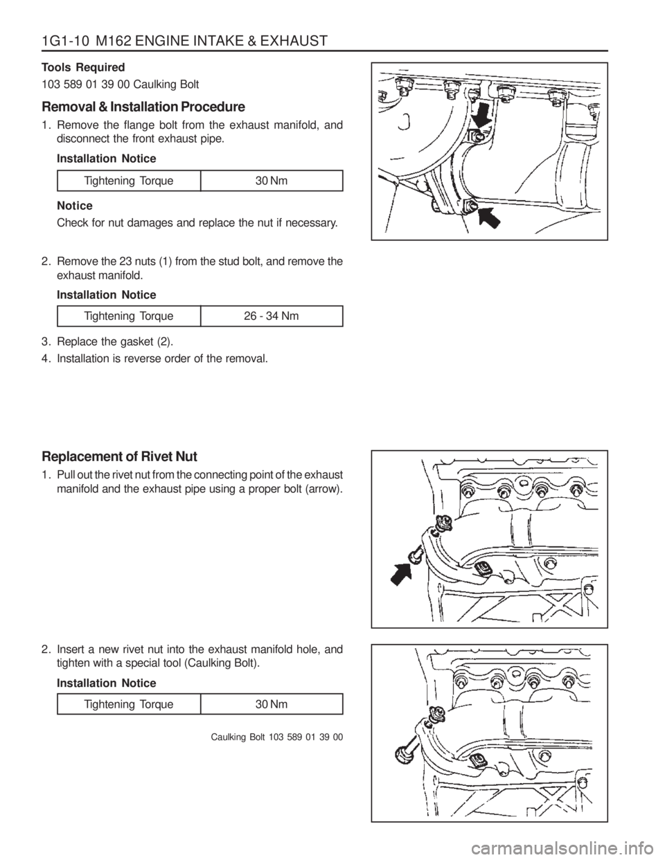
Tools Required 103 589 01 39 00 Caulking Bolt Removal & Installation Procedure
1. Remove the flange bolt from the exhaust manifold, anddisconnect the front exhaust pipe. Installation Notice Notice
Check for nut damages and replace the nut if necessary.
2. Remove the 23 nuts (1) from the stud bolt, and remove the exhaust manifold. Installation Notice
3. Replace the gasket (2).
4. Installation is reverse order of the removal. Replacement of Rivet Nut
1. Pull out the rivet nut from the connecting point of the exhaust manifold and the exhaust pipe using a proper bolt (arrow).
2. Insert a new rivet nut into the exhaust manifold hole, and tighten with a special tool (Caulking Bolt). Installation Notice
Caulking Bolt 103 589 01 39 00
Tightening Torque 30 Nm
Tightening Torque 26 - 34 Nm
Tightening Torque 30 Nm
Page 680 of 1574
1G2-8 M161 ENGINE INTAKE & EXHAUST
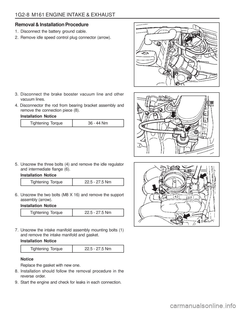
Removal & Installation Procedure
1. Disconnect the battery ground cable.
2. Remove idle speed control plug connector (arrow).
3. Disconnect the brake booster vacuum line and othervacuum lines.
4. Disconnector the rod from bearing bracket assembly and remove the connection piece (8). Installation Notice
Tightening Torque 36 - 44 Nm
5. Unscrew the three bolts (4) and remove the idle regulatorand intermediate flange (6). Installation Notice
Tightening Torque 22.5 - 27.5 Nm
6. Unscrew the two bolts (M8 X 16) and remove the support assembly (arrow). Installation Notice
7. Unscrew the intake manifold assembly mounting bolts (1) and remove the intake manifold and gasket.Installation Notice Notice Replace the gasket with new one.
8. Installation should follow the removal procedure in the reverse order.
9. Start the engine and check for leaks in each connection.
Tightening Torque 22.5 - 27.5 Nm
Tightening Torque 22.5 - 27.5 Nm
Page 681 of 1574
M161 ENGINE INTAKE & EXHAUST 1G2-9
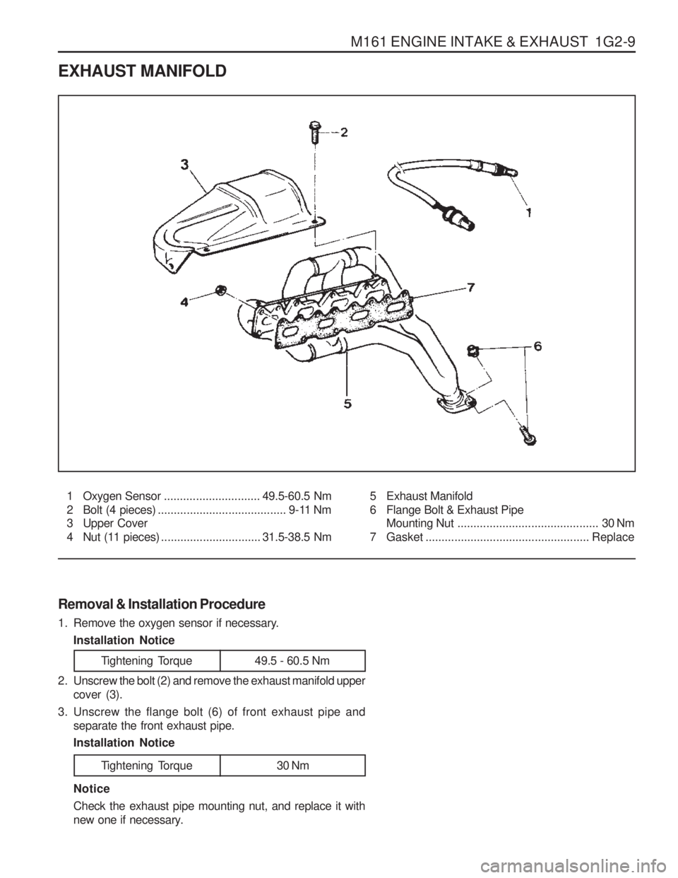
EXHAUST MANIFOLD
1 Oxygen Sensor.............................. 49.5-60.5 Nm
2 Bolt (4 pieces) ........................................ 9-11 Nm
3 Upper Cover
4 Nut (11 pieces) ............................... 31.5-38.5 Nm 5 Exhaust Manifold
6 Flange Bolt & Exhaust Pipe
Mounting Nut ............................................ 30 Nm
7 Gasket ................................................... Replace
Removal & Installation Procedure
1. Remove the oxygen sensor if necessary. Installation Notice
Tightening Torque 49.5 - 60.5 Nm
2. Unscrew the bolt (2) and remove the exhaust manifold upper cover (3).
3. Unscrew the flange bolt (6) of front exhaust pipe and separate the front exhaust pipe. Installation Notice
Tightening Torque 30 Nm
Notice Check the exhaust pipe mounting nut, and replace it with
new one if necessary.
Page 691 of 1574
OM600 ENGINE INTAKE & EXHAUST 1G3-7
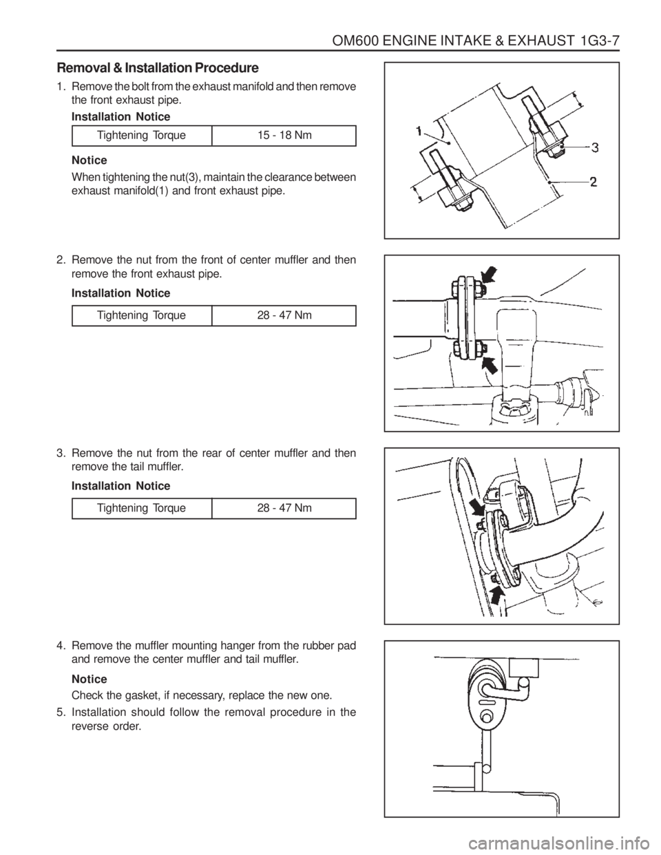
Removal & Installation Procedure
1. Remove the bolt from the exhaust manifold and then removethe front exhaust pipe. Installation Notice
Tightening Torque 15 - 18 Nm
Notice When tightening the nut(3), maintain the clearance between exhaust manifold(1) and front exhaust pipe.
2. Remove the nut from the front of center muffler and then remove the front exhaust pipe. Installation Notice
3. Remove the nut from the rear of center muffler and then remove the tail muffler.Installation Notice
4. Remove the muffler mounting hanger from the rubber pad and remove the center muffler and tail muffler. Notice
Check the gasket, if necessary, replace the new one.
5. Installation should follow the removal procedure in the reverse order.
Tightening Torque 28 - 47 Nm
Tightening Torque 28 - 47 Nm
Page 709 of 1574
2A-12 SUSPENSION DIAGNOSISSELF DIAGNOSIS TEST
DIAGNOSIS TEST
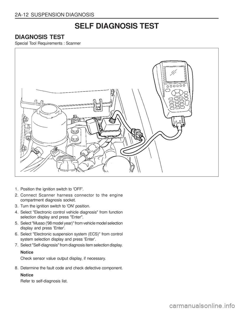
Special Tool Requirements : Scanner
1. Position the ignition switch to 'OFF'.
2. Connect Scanner harness connector to the engine compartment diagnosis socket.
3. Turn the ignition switch to 'ON' position.
4. Select "Electronic control vehicle diagnosis" from function selection display and press "Enter".
5. Select "Musso ('98 model year)" from vehicle model selection display and press 'Enter'.
6. Select "Electronic suspension system (ECS)" from control system selection display and press 'Enter'.
7. Select "Self-diagnosis" from diagnosis item selection display.
Notice
Check sensor value output display, if necessary.
8. Determine the fault code and check defective component. NoticeRefer to self-diagnosis list.
Page 719 of 1574
WHEEL ALIGNMENT 2B-9
GENERAL DESCRIPTION AND SYSTEM OPERATION
FOUR WHEEL ALIGNMENT CASTER Caster is the tilting 91 the uppermost point of the steering axis either forward or backward from the vertical when viewed from the side of the vehicle. A backward tilt is positive, and a forward tilt is negative. Caster influencesdirectional control of the steering but does not affect
tire wear. Weak springs or overloading a vehicle will affect
caster. One wheel with more positive caster will pull
toward the center of the car. This condition will cause the car to move or lean toward the side with the least
amount of positive caster. Caster is measured in degrees. CAMBER Camber is the tilting of the top of the tire from the vertical when viewed from the front of the vehicle. When thetires tilt outward, the camber is positive. When the tires tilt inward, the camber is negative. The camber angle is measured in degrees from the vertical. Camber
influences both directional control and tire wear.
If the vehicle has too much positive camber, the outside
shoulder of the tire will wear. If the vehicle has too much
negative camber, the inside shoulder of the tire will wear.
The first responsibility of engineering is to design safesteering and suspension systems. Each componentmust be strong enough to withstand and absorb extremepunishment. Both the steering system and the front and the rear suspension must function geometrically with thebody mass. The steering and the suspension systems require that the front wheels self-return and that the tire rolling effortand the road friction be held to a negligible force in orderto allow the customer to direct the vehicle with the least effort and the most comfort. A complete wheel alignment check should include
measurements of the rear toe and camber. Four-wheel alignment assures that all four wheels will be running in precisely the same direction. When the vehicle is geometrically aligned, fuel economy and tire life are at their peak, and steering andperformance are maximized. TOE
Toe-in is the turning in of the tires, while toe-out is the turning out of the tires from the geometric centerline or thrust line. The toe ensures parallel rolling of the wheels. The toe serves to offset the small deflections of the wheel support system which occur when the vehicle is rollingforward. The specified toe angle is the setting whichachieves 0 degrees of toe when the vehicle is moving. Incorrect toe-in or toe-out will cause tire wear and
reduced fuel economy. As the individual steering andsuspension components wear from vehicle mileage,
additional toe will be needed to compensate for the wear. Always correct the toe dimension last.
Page 755 of 1574
FRONT DRIVE AXLE 3A-5
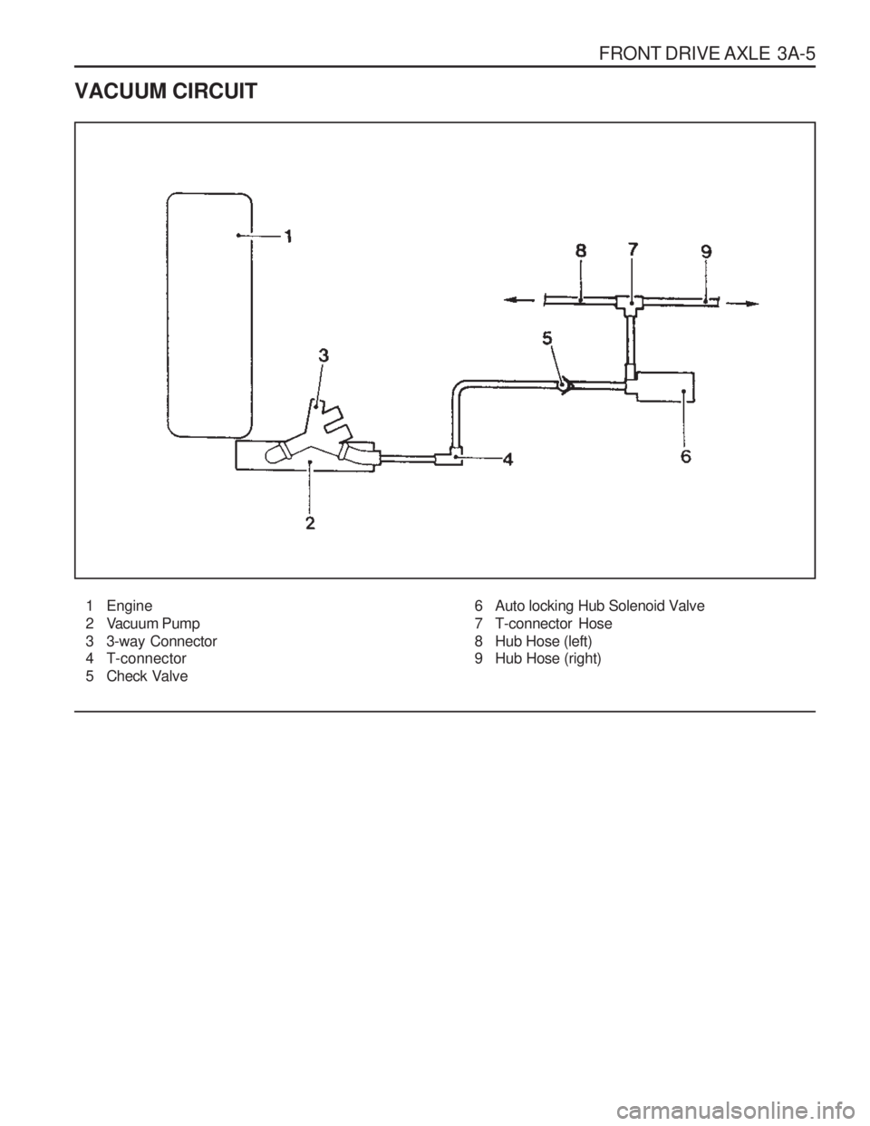
VACUUM CIRCUIT
1 Engine
2 Vacuum Pump
3 3-way Connector
4 T-connector
5 Check Valve 6 Auto locking Hub Solenoid Valve
7 T-connector Hose
8 Hub Hose (left)
9 Hub Hose (right)
Page 804 of 1574
HYDRAULIC BRAKES 4A-7
MAINTENANCE AND REPAIRON-VEHICLE SERVICE
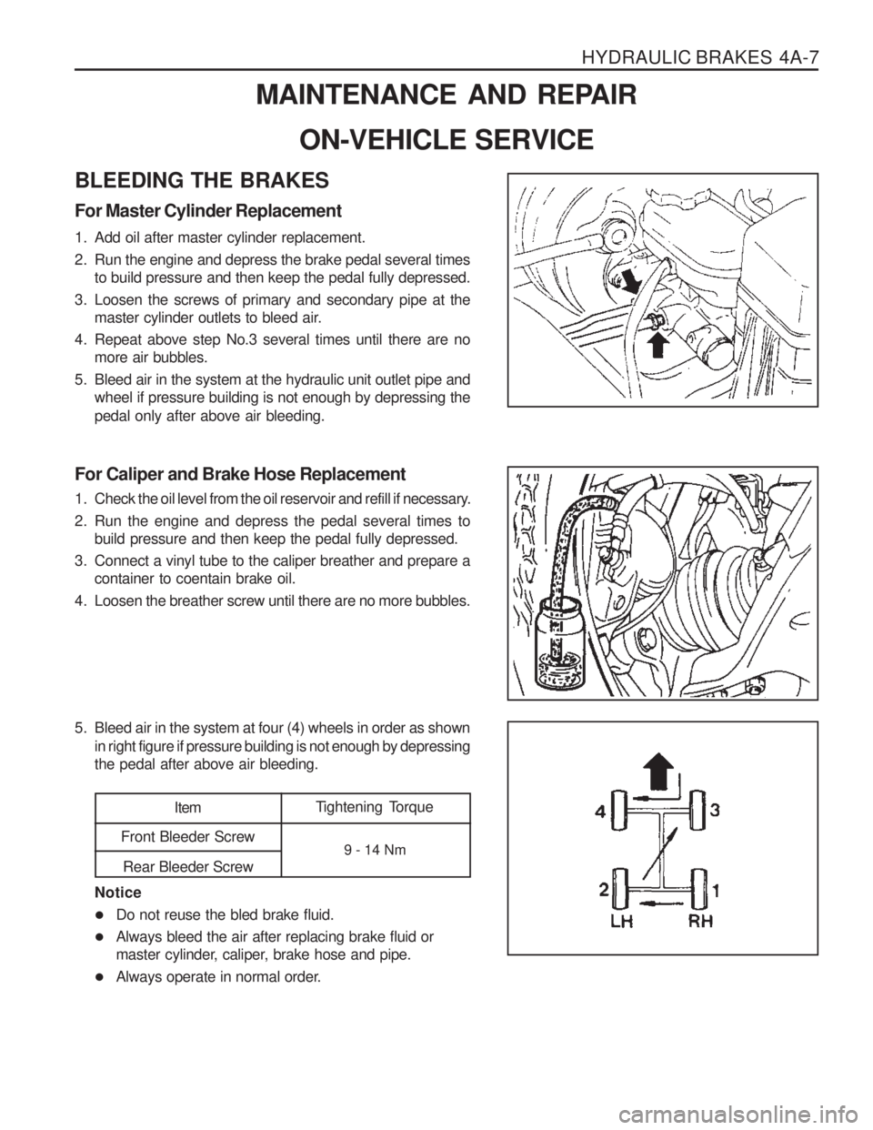
BLEEDING THE BRAKES For Master Cylinder Replacement
1. Add oil after master cylinder replacement.
2. Run the engine and depress the brake pedal several times to build pressure and then keep the pedal fully depressed.
3. Loosen the screws of primary and secondary pipe at the master cylinder outlets to bleed air.
4. Repeat above step No.3 several times until there are no more air bubbles.
5. Bleed air in the system at the hydraulic unit outlet pipe and wheel if pressure building is not enough by depressing the pedal only after above air bleeding.
For Caliper and Brake Hose Replacement
1. Check the oil level from the oil reservoir and refill if necessary.
2. Run the engine and depress the pedal several times to build pressure and then keep the pedal fully depressed.
3. Connect a vinyl tube to the caliper breather and prepare a container to coentain brake oil.
4. Loosen the breather screw until there are no more bubbles.
5. Bleed air in the system at four (4) wheels in order as shown in right figure if pressure building is not enough by depressing the pedal after above air bleeding.
Tightening Torque
9 - 14 NmItem
Front Bleeder Screw
Rear Bleeder Screw
Notice
� Do not reuse the bled brake fluid.
� Always bleed the air after replacing brake fluid or
master cylinder, caliper, brake hose and pipe.
� Always operate in normal order.
Page 927 of 1574
5A-68 AUTOMATIC TRANSMISSION
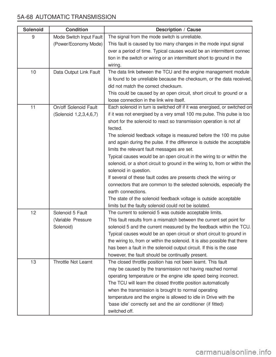
Description / Cause
The signal from the mode switch is unreliable.
This fault is caused by too many changes in the mode input signal
over a period of time. Typical causes would be an intermittent connec
tion in the switch or wiring or an intermittent short to ground in thewiring.
The data link between the TCU and the engine management module
is found to be unreliable because the checksum, or the data received, did not match the correct checksum.
This could be caused by an open circuit, short circuit to ground or aloose connection in the link wire itself.
Each solenoid in turn is switched off if it was energised, or switched on
if it was not energised by a very small 100 ms pulse. This pulse is too
short for the solenoid to react so transmission operation is not af fected.
The solenoid feedback voltage is measured before the 100 ms pulse
and again during the pulse. If the difference is outside the acceptablelimits the relevant fault messages are set.
Typical causes would be an open circuit in the wiring to or within the
solenoid, or a short circuit to ground in the wiring to, from or within thesolenoid in question.If several of these fault codes are presents check the wiring or
connectors that are common to the selected solenoids, especially the earth connections.
The state of the solenoid feedback voltage is outside acceptablelimits but the faulty solenoid could not be isolated.The current to solenoid 5 was outside acceptable limits.
This fault results from a mismatch between the current set point for
solenoid 5 and the current measured by the feedback within the TCU.
Typical causes would be an open circuit or short circuit to ground in
the wiring to, from or within the solenoid. It is also possible that there
has been a fault in the solenoid output circuit. If this is the case
however, the fault should be continually present.
The closed throttle position has not been learnt. This fault may be caused by the transmission not having reached normaloperating temperature or the engine idle speed being incorrect.The TCU will learn the closed throttle position automatically when the transmission is brought to normal operating temperature and the engine is allowed to idle in Drive with the‘ base idle ’ correctly set and the air conditioner (if fitted)
switched off.
Condition
Mode Switch Input Fault(Power/Economy Mode) Data Output Link Fault On/off Solenoid Fault (Solenoid 1,2,3,4,6,7) Solenoid 5 Fault
(Variable Pre ssure
Solenoid) Throttle Not LearntSolenoid
9
10 11 12 13