SSANGYONG MUSSO 2003 Service Manual
MUSSO 2003
SSANGYONG
SSANGYONG
https://www.carmanualsonline.info/img/67/57511/w960_57511-0.png
SSANGYONG MUSSO 2003 Service Manual
Page 528 of 1574

1E3-4 OM600 ENGINE ELECTRICAL
Preheating System Operation
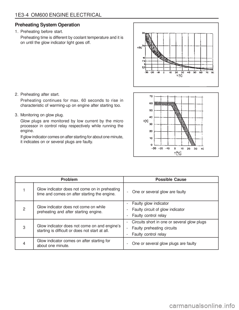
1. Preheating before start.Preheating time is different by coolant temperature and it is on until the glow indicator light goes off.
2. Preheating after start. Preheating continues for max. 60 seconds to rise in characteristic of warming-up on engine after starting too.
3. Monitoring on glow plug. Glow plugs are monitored by low current by the microprocessor in control relay respectively while running theengine. If glow indicator comes on after starting for about one minute,
it indicates on or several plugs are faulty.
Possible Cause
- One or several glow are faulty
Problem
Glow indicator does not come on in preheating time and comes on after starting the engine. Glow indicator does not come on while preheating and after starting engine. Glow indicator does not come on and engine
’s
starting is difficult or does not start at all. Glow indicator comes on after starting for about one minute.1 2 3 4 - Faulty glow indicator
- Faulty circuit of glow indicator
- Faulty control relay
- Circuits short in one or several glow plugs
- Faulty preheating circuits
- Faulty control relay
- One or several glow plugs are faulty
Page 529 of 1574
OM600 ENGINE ELECTRICAL 1E3-5
Removal & Installation Procedure
1. Disconnect the negative terminal of battery.
2. Remove the nut (2).
3. Remove the glow plug (4).
4. Install the glow plug (4).
5. Tighten the nut (2).
Tightening Torque 20 Nm
Tightening Torque 4 Nm
Page 530 of 1574
1E3-6 OM600 ENGINE ELECTRICAL
ALTERNATOR Preceding Work : Removal of poly V-belt
1 Cooling Fan
2 Bolt............................................................ 45Nm
3 Bolt ............................................................ 45Nm4 Alternator
5 Plug Connection
Page 531 of 1574
OM600 ENGINE ELECTRICAL 1E3-7
Removal & Installation Procedure
1. Disconnect the negative terminal of the battery.
2. Disconnect the plug connection (5).
3. OM 662 EngineAlign the groove of cooling fan with bolt (2) (arrow).
4. Remove the bolts (2, 3) and take out the alternator.
5. Installation should follow the removal procedure in the reverse order.
Tightening Torque 45 Nm
Page 532 of 1574
1E3-8 OM600 ENGINE ELECTRICAL
STARTER MOTOR
1 Starter Motor
2 Washer3 Nut .............................................................
15Nm
4 Bolt ............................................................ 48Nm
Removal & Installation Procedure
1. Disconnect the battery terminals.
2. Disconnect the starter motor cable harnesses.
3. Remove the bolts and then remove the starter motor.
4. Installation should follow the removal procedure in the
reverse order.
Page 533 of 1574

SECTION 1F1
M162 ENGINE CONTROLS
TABLE OF CONTENTS
CAUTION: Disconnect the negative battery cable before removing or installing any electrical unit or when a tool or equipment could easily come in contact with exposed electrical terminals. Disconnecting this cablewill help prevent personal injury and damage to the vehicle. The ignition must also be in LOCK unless otherwisenoted.
Specifications . . . . . . . . . . . . . . . . . . . . . . . 1F1-2
Fastener Tightening Specifications . . . . . . . . 1F1-2
Special Tools . . . . . . . . . . . . . . . . . . . . . . . 1F1-3 Special Tools Table . . . . . . . . . . . . . . . . . . . . 1F1-3
Schematic and Routing Diagrams . . . . . . . 1F1-4 E32 ECU (HFM) . . . . . . . . . . . . . . . . . . . . . . 1F1-4
E32 ECU (MSE) . . . . . . . . . . . . . . . . . . . . . . 1F1-5
Diagnosis . . . . . . . . . . . . . . . . . . . . . . . . . . 1F1-6
Self Diagnosis Socket Pin Numbers andDescriptions . . . . . . . . . . . . . . . . . . . . . . . . 1F1-6
Self Diagnosis Failure Code . . . . . . . . . . . . . 1F1-7
Test Box Connection . . . . . . . . . . . . . . . . . . 1F1-10
Fuel Injection System Test (MSE3.62) . . . . . 1F1-11
Ignition System Test . . . . . . . . . . . . . . . . . . 1F1-21
Idling Control and Electronic Pedal System Test . . . . . . . . . . . . . . . . . . . . . . . 1F1-26
Air Conditioner Control System Test . . . . . . 1F1-28
Fuel Pressure and Internal Leakage Test . . 1F1-29
Fuel Pump Test . . . . . . . . . . . . . . . . . . . . . . 1F1-31Injector Test . . . . . . . . . . . . . . . . . . . . . . . .
1F1-33
Maintenance and Repair . . . . . . . . . . . . . 1F1-35
On-Vehicle Service . . . . . . . . . . . . . . . . . . . . 1F1-35
ECU . . . . . . . . . . . . . . . . . . . . . . . . . . . . . . 1F1-35
Fuel Pressure Regulator . . . . . . . . . . . . . . 1F1-46
Fuel Distributor . . . . . . . . . . . . . . . . . . . . . . 1F1-50
Injector . . . . . . . . . . . . . . . . . . . . . . . . . . . . 1F1-54
Fuel Filter . . . . . . . . . . . . . . . . . . . . . . . . . . 1F1-57
Fuel Pump . . . . . . . . . . . . . . . . . . . . . . . . . 1F1-58
Purge Switchover Valve . . . . . . . . . . . . . . . 1F1-62
Vacuum System . . . . . . . . . . . . . . . . . . . . . 1F1-64
Crankshaft Position Sensor . . . . . . . . . . . . 1F1-65
Camshaft Position Sensor . . . . . . . . . . . . . 1F1-67
Hot Film Air Mass (HFM) Sensor . . . . . . . . . 1F1-69
Oxygen Sensor . . . . . . . . . . . . . . . . . . . . . . 1F1-72
Knock Sensor . . . . . . . . . . . . . . . . . . . . . . . 1F1-74
Coolant Temperature Sensor . . . . . . . . . . . 1F1-75
Accelerator Pedal Module . . . . . . . . . . . . . . 1F1-78
Page 534 of 1574
1F1-2 M162 ENGINE CONTROLSSPECIFICATIONS
FASTENER TIGHTENING SPECIFICATIONS
Application
Fuel Return and Supply Line Fuel Distributor Assembly Bolt
Pressure Test ConnectorFuel Inlet and Outlet LineFuel Filter Mounting Bracket Bolt Crankshaft Position Sensor Bolt Camkshaft Position Sensor BoltKnock Sensor Mounting Bolt
Coolant Temperature BoltN m
25 - 30
22.5 - 27.5 21.6 - 26.4 25 - 304 - 8
9 - 11
9 - 11
22.5 - 27.5 18 - 22
Page 535 of 1574
M162 ENGINE CONTROLS 1F1-3
SPECIAL TOOLS
SPECIAL TOOLS TABLE
129 589 00 21 00 Test Box
119 589 04 63 00Pressure Hose
106 589 00 21 00Pressure Tester
210 589 08 63 00 ECU Test Cable 210201Adaptor line
Page 536 of 1574
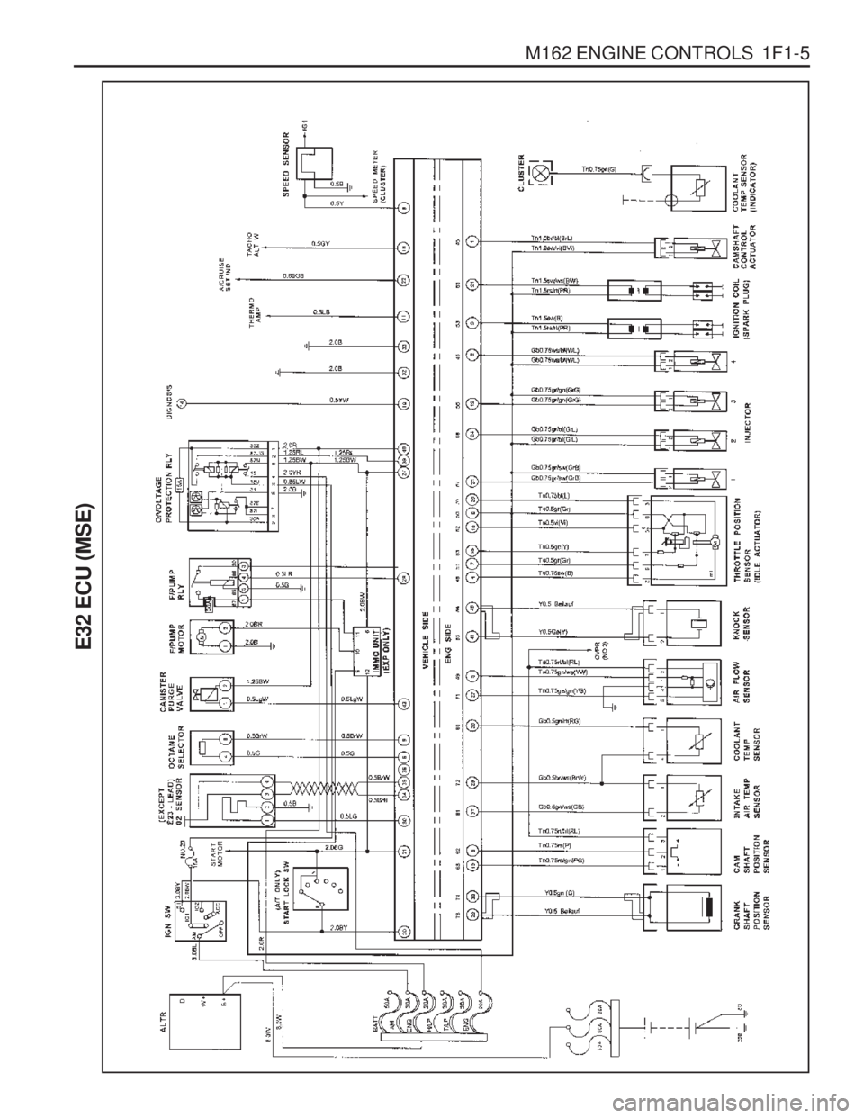
M162 ENGINE CONTROLS 1F1-5
E32 ECU (MSE)
Page 537 of 1574
1F1-4 M162 ENGINE CONTROLS
E32 ECU (HFM)
SCHEMATIC AND ROUTING DIAGRAMS


