SSANGYONG NEW ACTYON SPORTS 2012 Service Manual
NEW ACTYON SPORTS 2012
SSANGYONG
SSANGYONG
https://www.carmanualsonline.info/img/67/57513/w960_57513-0.png
SSANGYONG NEW ACTYON SPORTS 2012 Service Manual
Trending: fuse box, radio antenna, jump start, oil reset, change key battery, recommended oil, oil level
Page 491 of 828
03-137010-06
5. REKES OPERATION LOGIC
1) Remote Door Lock
When briefly pressing the door lock switch on the remote control key for less than 0.5
seconds, all doors are locked.
The system outputs the "LOCK" signal immediately after receiving the door lock message from
the remote control key. If the vehicle is locked while all doors including engine hood are
closed, the theft deterrent mode is activated (hazard warning lamps are blinking twice). 1.
2.
Page 492 of 828
03-14
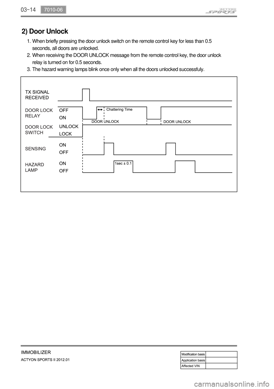
2) Door Unlock
When briefly pressing the door unlock switch on the remote control key for less than 0.5
seconds, all doors are unlocked.
When receiving the DOOR UNLOCK message from the remote control key, the door unlock
relay is turned on for 0.5 seconds.
The hazard warning lamps blink once only when all the doors unlocked successfuly. 1.
2.
3.
Page 493 of 828
03-157010-06
3) Remote Escort
When you press and hold the PANIC button (more than 0.5 seconds) the escort function is
activated.
The headlamp comes on for 20 seconds and goes off automatically, when the escort
message is received from the remote control key. 1.
2.
4) Remote Panic
When pressing and holding the PANIC button on the remote control key for more than 2
seconds, the panic function is activated.
The vehicle activates the panic alarm by using the horn for 27 seconds when receiving the
panic message from the remote control key. 1.
2.
Page 494 of 828
04-38210-01
1. SPECIFICATIONS
Item Specification
Rated voltage DC 13.5 V
Operating voltage DC 9 V ~ 16 V
Checking voltage DC 13.5 V
Operating temperature-30℃ ~ +80℃
Storage temperature-40℃ ~ +85℃
Illumination color Dial White
Pointer Red
LCD Red
Gear position display in A/T
(Left hand of LCD display)P, R, N, D, 1, 2, 3, 4, 5 and 6
Page 495 of 828

04-4
1. DESCRIPTIONS OF INDICATOR DISPLAY
Tachometer
ESP indicator/warning light
Immobilizer indicator
Glow indicator
Front fog light indicator
High beam indicator
ESP OFF indicator
Seat belt reminder (driver’s seat)
Seat belt reminder (passenger’s seat)
Engine oil pressure warning light
LCD Display
Engine overheat warning light
Engine check warning light
Auto cruise indicator
Light indicator
Winter mode indicator 1.
2.
3.
4.
5.
6.
7.
8.
9.
10.
11.
12.
13.
14.
15.
16.Engine hood open warning light
Battery charge warning light
Hazard Indicator
Water separator warning light
Air bag warning light
4WD CHECK warning light
4WD LOW indicator
4WD HIGH indicator
Speedometer
Turn signal indicator
Coolant temperature gauge
Brake warning light
Door ajar warning light
ABS warning light
Fuel gauge
Low fuel level warning light 17.
18.
19.
20.
21.
22.
23.
24.
25.
26.
27.
28.
29.
30.
31.
32. It sends and receives information to/from each unit through CAN communication line. The LCD
display and separate ESP ON/OFF indicator are newly added.
Page 496 of 828
04-58210-01
B. Sub connector (gray)A. Main connector (white)
System Layout ▶
Front view
Rear view
NO.1 NO.10
NO.11
NO.20NO.1
NO.20 NO.10
NO.11
Page 497 of 828
04-6
Connector Pin Arrangement ▶
The connector pin sections illustrated below are viewed from the front of the instrument
cluster. The arrangement of the pins is the same for both the main connector and the sub
connector.
Main connector - 20-pin (white)
Sub connector - 20-pin (gray)
1. -
2. Hood open
3. Seat belt - passenger's seat
4. -
5. -
6. Front fog lamp
7. -
8. Engine CHECK warning light
9. Charge
10. IGN 2
11. -
12. Air bag
13. Seat belt - driver's seat
14. High beam (-)
15. Right turn signal lamp (+)
16. High beam (+)
17. Left turn signal lamp (+)
18. Oil pressure
19. Parking brake signal input (STICS)
20. - 1. -
2. -
3. 4P output
4. Buzzer output
5. Illumination (+)
6. -
7. -
8. Door open
9. -
10. Battery
11. -
12. Fuel input signal
13. TRIP mode/reset switch
14. Manual transmission N (neutral)
input
15. Manual transmission R (reverse)
input
16. CAN LOW
17. CAN HIGH
18. AGND (fuel -)
19. MICOM ground
20. IGN 1
Page 498 of 828
04-78210-01
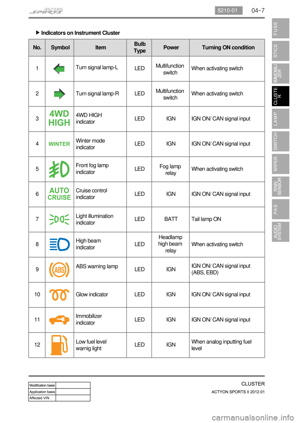
Indicators on Instrument Cluster ▶
No. Symbol ItemBulb
TypePower Turning ON condition
1Turn signal lamp-L
LEDMultifunction
switchWhen activating switch
2 Turn signal lamp-R LEDMultifunction
switchWhen activating switch
34WD HIGH
indicatorLED IGN IGN ON/ CAN signal input
4Winter mode
indicatorLED IGN IGN ON/ CAN signal input
5Front fog lamp
indicatorLEDFog lamp
relayWhen activating switch
6Cruise control
indicatorLED IGN IGN ON/ CAN signal input
7Light illumination
indicator LED BATT Tail lamp ON
8High beam
indicatorLEDHeadlamp
high beam
relayWhen activating switch
9ABS warning lamp
LED IGNIGN ON/ CAN signal input
(ABS, EBD)
10 Glow indicator LED IGN IGN ON/ CAN signal input
11Immobilizer
indicatorLED IGN IGN ON/ CAN signal input
12Low fuel level
warnig lightLED IGNWhen analog inputting fuel
level
Page 499 of 828
04-8
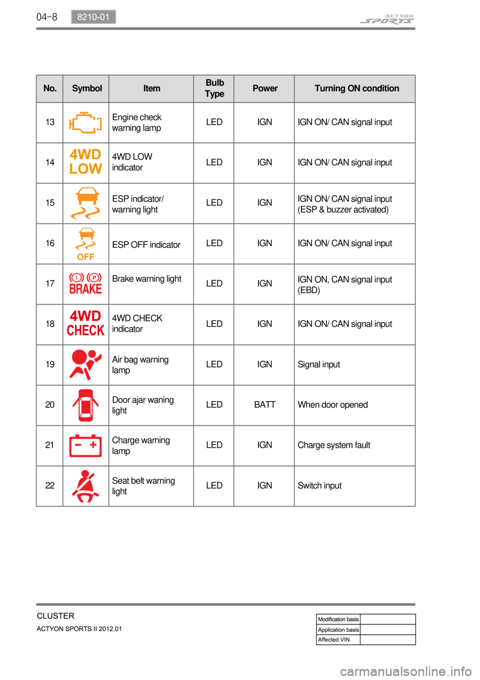
No. Symbol ItemBulb
TypePower Turning ON condition
13Engine check
warning lampLED IGN IGN ON/ CAN signal input
144WD LOW
indicatorLED IGN IGN ON/ CAN signal input
15ESP indicator/
warning lightLED IGNIGN ON/ CAN signal input
(ESP & buzzer activated)
16
ESP OFF indicatorLED IGN IGN ON/ CAN signal input
17Brake warning light
LED IGNIGN ON, CAN signal input
(EBD)
184WD CHECK
indicatorLED IGN IGN ON/ CAN signal input
19Air bag warning
lampLED IGN Signal input
20Door ajar waning
lightLED BATT When door opened
21Charge warning
lampLED IGN Charge system fault
22Seat belt warning
lightLED IGN Switch input
Page 500 of 828
04-98210-01
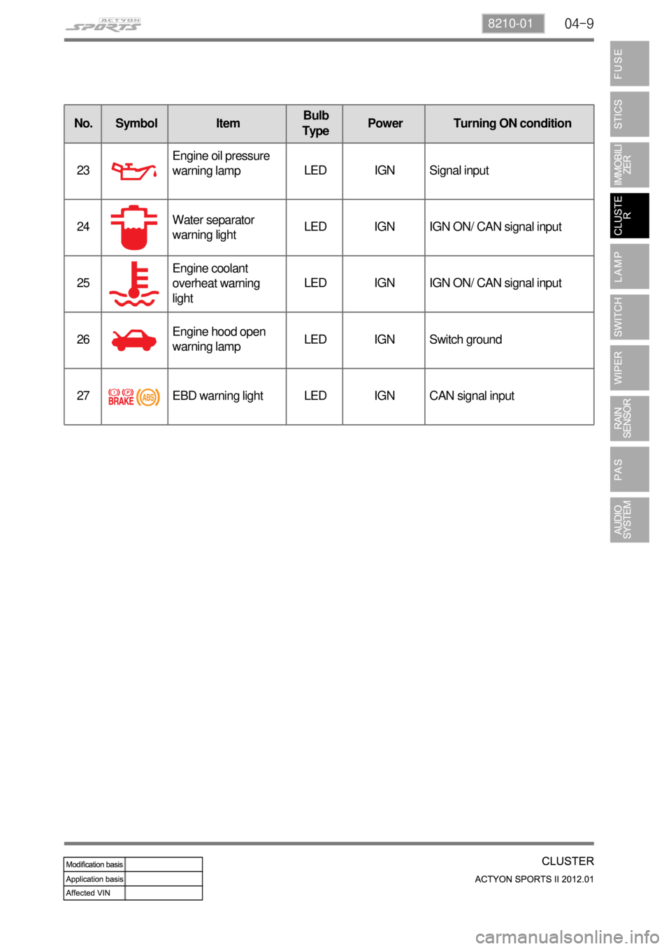
No. Symbol ItemBulb
TypePower Turning ON condition
23Engine oil pressure
warning lampLED IGN Signal input
24Water separator
warning lightLED IGN IGN ON/ CAN signal input
25Engine coolant
overheat warning
lightLED IGN IGN ON/ CAN signal input
26Engine hood open
warning lampLED IGN Switch ground
27 EBD warning light LED IGN CAN signal input
Trending: driver seat adjustment, gas type, coolant capacity, height, fuel consumption, timing belt, phone


