SUBARU FORESTER 2004 Service Repair Manual
Manufacturer: SUBARU, Model Year: 2004, Model line: FORESTER, Model: SUBARU FORESTER 2004Pages: 2870, PDF Size: 38.67 MB
Page 1711 of 2870

Page 1712 of 2870

ENGINE (DIAGNOSTIC)
EN(H4DOTC)
Page
1. Basic Diagnostics Procedure ......................................................................2
2. Check List for Interview ...............................................................................4
3. General Description ....................................................................................6
4. Electrical Component Location ...................................................................9
5. Engine Control Module (ECM) I/O Signal .................................................23
6. Engine Condition Data ..............................................................................27
7. Transmission Control Module (TCM) I/O Signal .......................................28
8. Data Link Connector .................................................................................29
9. OBD-II General Scan Tool ........................................................................30
10. Subaru Select Monitor...............................................................................33
11. Read Diagnostic Trouble Code (DTC) ......................................................39
12. Inspection Mode ........................................................................................40
13. Drive Cycle ................................................................................................45
14. Clear Memory Mode..................................................................................47
15. Compulsory Valve Operation Check Mode ...............................................48
16. Malfunction Indicator Light ........................................................................50
17. Diagnostics for Engine Starting Failure .....................................................59
18. List of Diagnostic Trouble Code (DTC) .....................................................74
19. Diagnostic Procedure with Diagnostic Trouble Code (DTC) .....................80
20. General Diagnostic Table........................................................................295
Page 1713 of 2870

EN(H4DOTC)-80
ENGINE (DIAGNOSTIC)
Diagnostic Procedure with Diagnostic Trouble Code (DTC)
19.Diagnostic Procedure with Diagnostic Trouble Code (DTC)
A: DTC P0011 “A” CAMSHAFT POSITION - TIMING OVER - ADVANCED OR
SYSTEM PERFORMANCE (BANK 1)
DTC DETECTING CONDITION:
Detect as soon as the malfunction occurs.
TROUBLE SYMPTOM:
Engine stalls.
Erroneous idling
CAUTION:
After repair or replacement of faulty parts, conduct Clear Memory Mode
Step Check Yes No
1 CHECK DTC ON DISPLAY.Is any other DTC displayed? Inspect the rele-
vant DTC using
“List of Diagnostic
Trouble Code
(DTC)”.
List of Diagnostic
Trouble Code
(DTC).>Go to step 2.
2 CHECK CURRENT DATA.
1) Start the engine and idle it.
2) Check the AVCS system operating angle
and oil flow control solenoid valve duty output
using Subaru Select Monitor or OBD-II general
scan tool.
N
OTE:
Subaru Select Monitor
For detailed operation procedure, refer to
“READ CURRENT DATA SHOWN ON DIS-
PLAY FOR ENGINE”.
OBD-II general scan tool
For detailed operation procedures, refer to the
OBD-II General Scan Tool Operation Manual.Is the AVCS system operating
angle approx. 0 degree and oil
flow control solenoid valve duty
output approx. 10%?A temporary poor
malfunction. Per-
for m the following
to clean oil routing.
Replace the
engine oil, and
then idle the
engine for 5 min-
utes and replace
the oil filter and
engine oil.Check the follow-
ing and repair or
replace it if neces-
sary.
Oil pipe (clog-
ging)
Oil flow con-
trol solenoid
valve (clogging
or dirt of oil
routing, spring
setting, clog-
ging of valve)
Intake cam-
shaft (dirt, dam-
age of
camshaft)
Timing belt
(alignment of
timing mark)
Page 1714 of 2870

EN(H4DOTC)-81
ENGINE (DIAGNOSTIC)
Diagnostic Procedure with Diagnostic Trouble Code (DTC)
B: DTC P0021 “A” CAMSHAFT POSITION - TIMING OVER - ADVANCED OR
SYSTEM PERFORMANCE (BANK 2)
DTC DETECTING CONDITION:
Detect as soon as the malfunction occurs.
TROUBLE SYMPTOM:
Engine stalls.
Erroneous idling
CAUTION:
After repair or replacement of faulty parts, conduct Clear Memory Mode
Step Check Yes No
1 CHECK DTC ON DISPLAY.Is any other DTC displayed? Inspect the rele-
vant DTC using
“List of Diagnostic
Trouble Code
(DTC)”.
List of Diagnostic
Trouble Code
(DTC).>Go to step 2.
2 CHECK CURRENT DATA.
1) Start the engine and idle it.
2) Check the AVCS system operating angle
and oil flow control solenoid valve duty output
using Subaru Select Monitor or OBD-II general
scan tool.
NOTE:
Subaru Select Monitor
For detailed operation procedure, refer to
“READ CURRENT DATA SHOWN ON DIS-
PLAY FOR ENGINE”.
OBD-II general scan tool
For detailed operation procedures, refer to the
OBD-II General Scan Tool Operation Manual.Is the AVCS system operating
angle approx. 0 degree and oil
flow control solenoid valve duty
output approx. 10%?A temporary poor
malfunction. Per-
for m the following
to clean oil routing.
Replace the
engine oil, and
then idle the
engine for 5 min-
utes and replace
the oil filter and
engine oil.Check the follow-
ing and repair or
replace it if neces-
sary.
Engine oil
(amount, dirt)
Oil pipe (clog-
ging)
Oil flow con-
trol solenoid
valve (clogging
or dirt of oil
routing, spring
setting, clog-
ging of valve)
Intake cam-
shaft (dirt, dam-
age of
camshaft)
Timing belt
(alignment of
timing mark)
Page 1715 of 2870

EN(H4DOTC)-82
ENGINE (DIAGNOSTIC)
Diagnostic Procedure with Diagnostic Trouble Code (DTC)
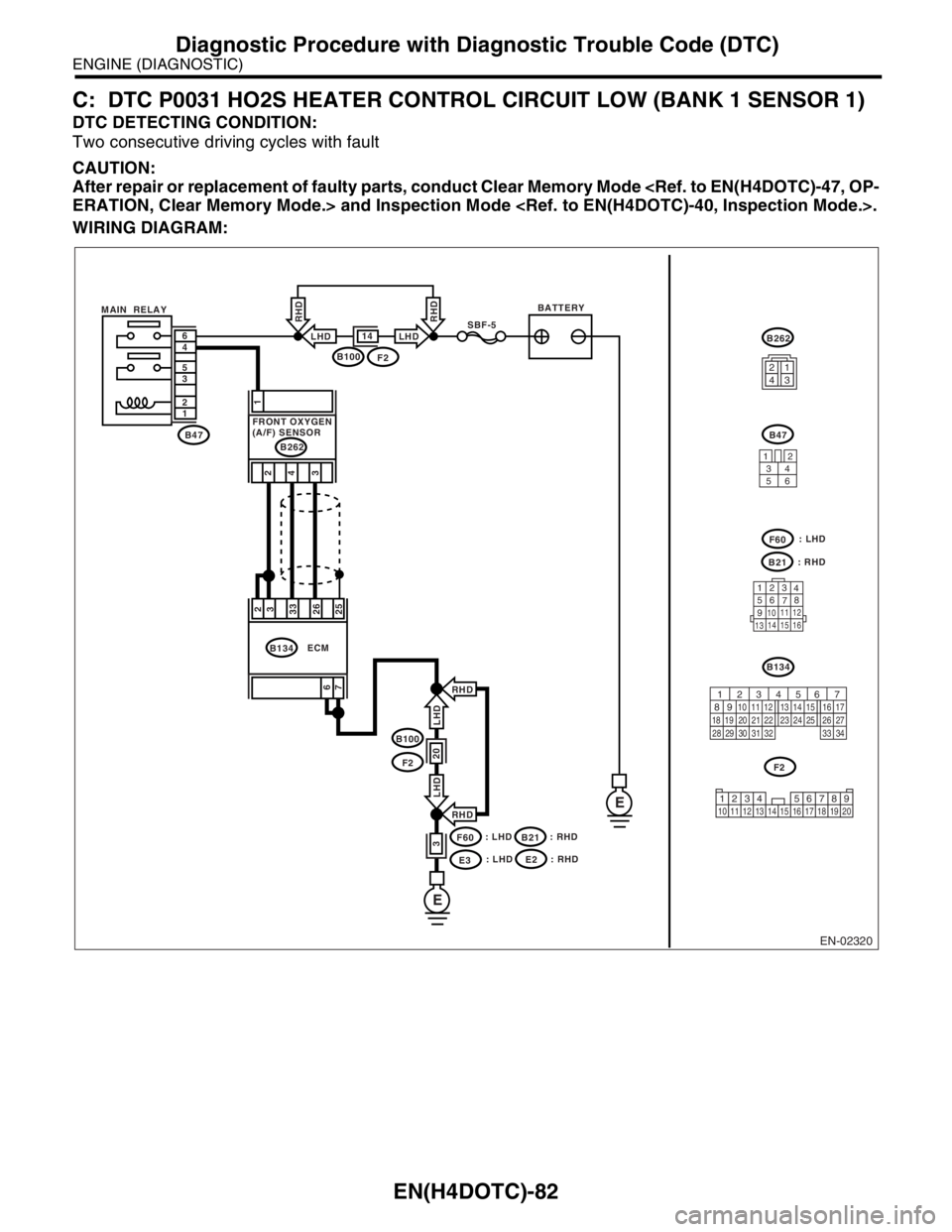
C: DTC P0031 HO2S HEATER CONTROL CIRCUIT LOW (BANK 1 SENSOR 1)
DTC DETECTING CONDITION:
Two consecutive driving cycles with fault
CAUTION:
After repair or replacement of faulty parts, conduct Clear Memory Mode
WIRING DIAGRAM:
EN-02320
BATTERYMAIN RELAYSBF-5
B47 1 2 3 5 4 6
E
E
B100F2
14LHD
RHD
LHD
RHD
B100
F2
F60
E3
20
3
RHD
RHD6
72
3
33
26
25
ECMB134
: LHD: LHD
B21: RHD: RHD
1
4 2
3
B262
FRONT OXYGEN
(A/F) SENSOR
3412
56
123
4
56
78
9
1011 12
1314 15 16
B21
F60
B47
B262
B134
F2
LHD LHD
1234
56 7
82 1
94 310
24 22 23 25 11 12 13 14 15
26 27
2816 17
18 19 20 21
33 34 29
32 30 31
1234 5678910 11 12 13 14 15 16 17 18 19 20
: LHDE2: RHD
Page 1716 of 2870

EN(H4DOTC)-83
ENGINE (DIAGNOSTIC)
Diagnostic Procedure with Diagnostic Trouble Code (DTC)
Step Check Yes No
1 CHECK HARNESS BETWEEN ECM AND
FRONT OXYGEN (A/F) SENSOR CONNEC-
TOR.
1) Start the engine, and warm-up the engine.
2) Turn the ignition switch to OFF.
3) Disconnect the connector from ECM and
front oxygen (A/F) sensor.
4) Measure the resistance of harness
between ECM and front oxygen (A/F) sensor
connector.
Connector & terminal
(B134)No. 2 — (B262)No. 2:
(B134)No. 3 — (B262)No. 2:Is the resistance less than 1
Ω?Go to step 2.Repair the open
circuit in harness
between ECM and
front oxygen (A/F)
sensor connector.
2 CHECK HARNESS BETWEEN ECM AND
FRONT OXYGEN (A/F) SENSOR CONNEC-
TOR.
Measure the resistance of harness between
ECM and front oxygen (A/F) sensor connector.
Connector & terminal
(B134) No. 33 — (B262) No. 4:
(B134) No. 26 — (B262) No. 3:Is the resistance less than 1
Ω?Go to step 3.Repair the open
circuit in harness
between ECM and
front oxygen (A/F)
sensor connector.
3 CHECK HARNESS BETWEEN ECM AND
FRONT OXYGEN (A/F) SENSOR CONNEC-
TOR.
Measure the resistance of harness between
main relay and front oxygen (A/F) sensor con-
nector.
Connector & terminal
(B47) No. 4 — (B262) No. 1:Is the resistance less than 1
Ω?Go to step 4.Repair the open
circuit in harness
between ECM and
front oxygen (A/F)
sensor connector.
4 CHECK FRONT OXYGEN (A/F) SENSOR.
Measure the resistance between front oxygen
(A/F) sensor connector terminals.
Te r m i n a l s
No. 2 — No. 1:Is the resistance less than 5
Ω?Go to step 5.Replace the front
oxygen (A/F) sen-
sor.
Front Oxygen (A/
F) Sensor.>
5 CHECK POOR CONTACT.
Check poor contact in ECM and front oxygen
(A/F) sensor connector. Is there poor contact in ECM or
front oxygen (A/F) sensor con-
nector?Repair the poor
contact in ECM
and front oxygen
(A/F) sensor.Replace the front
oxygen (A/F) sen-
sor.
Front Oxygen (A/
F) Sensor.>
Page 1717 of 2870

EN(H4DOTC)-84
ENGINE (DIAGNOSTIC)
Diagnostic Procedure with Diagnostic Trouble Code (DTC)
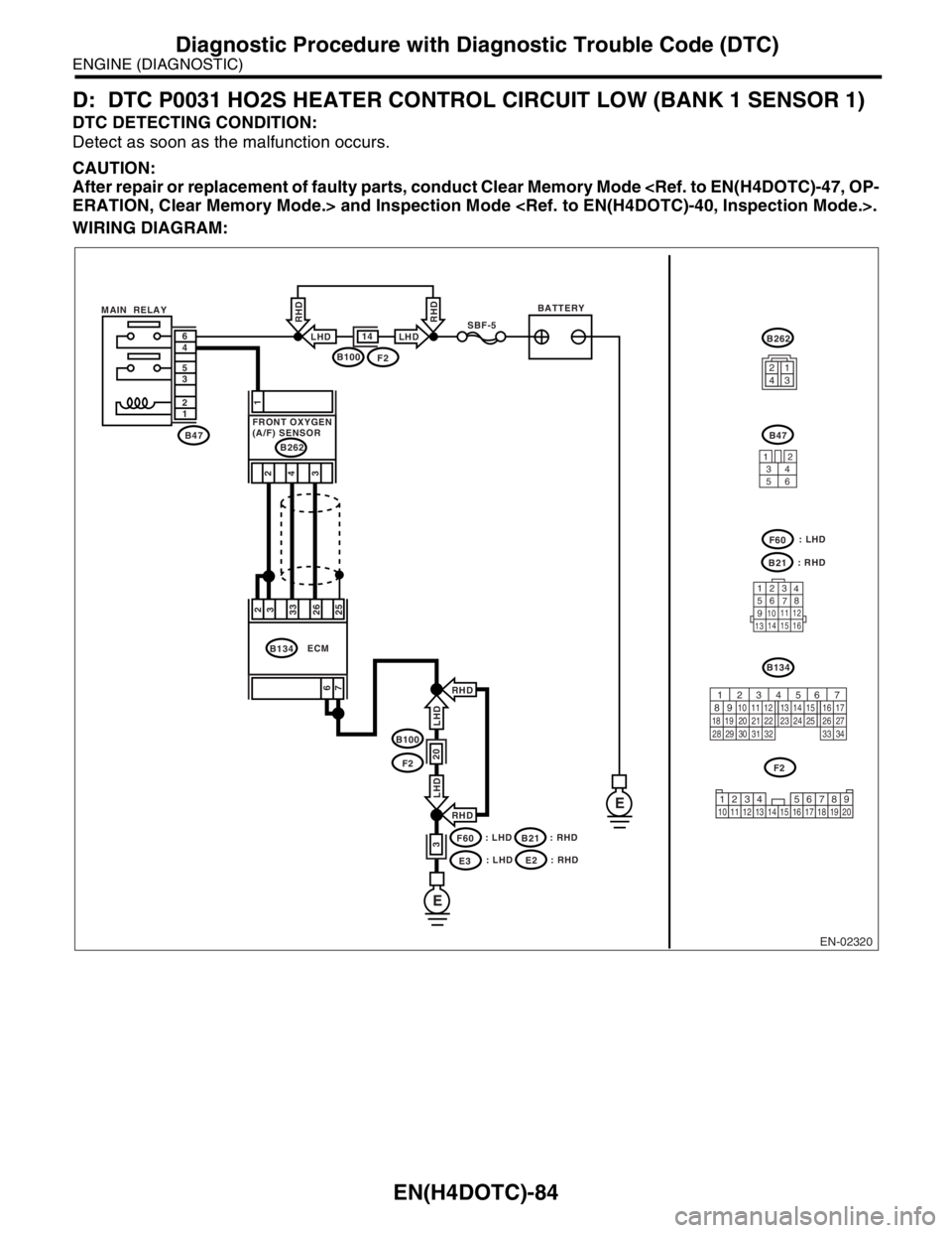
D: DTC P0031 HO2S HEATER CONTROL CIRCUIT LOW (BANK 1 SENSOR 1)
DTC DETECTING CONDITION:
Detect as soon as the malfunction occurs.
CAUTION:
After repair or replacement of faulty parts, conduct Clear Memory Mode
WIRING DIAGRAM:
EN-02320
BATTERYMAIN RELAYSBF-5
B47 1 2 3 5 4 6
E
E
B100F2
14LHD
RHD
LHD
RHD
B100
F2
F60
E3
20
3
RHD
RHD6
72
3
33
26
25
ECMB134
: LHD: LHD
B21: RHD: RHD
1
4 2
3
B262
FRONT OXYGEN
(A/F) SENSOR
3412
56
123
4
56
78
9
1011 12
1314 15 16
B21
F60
B47
B262
B134
F2
LHD LHD
1234
56 7
82 1
94 310
24 22 23 25 11 12 13 14 15
26 27
2816 17
18 19 20 21
33 34 29
32 30 31
1234 5678910 11 12 13 14 15 16 17 18 19 20
: LHDE2: RHD
Page 1718 of 2870

EN(H4DOTC)-85
ENGINE (DIAGNOSTIC)
Diagnostic Procedure with Diagnostic Trouble Code (DTC)
Step Check Yes No
1 CHECK POWER SUPPLY TO FRONT OXY-
GEN (A/F) SENSOR.
1) Turn the ignition switch to OFF.
2) Disconnect the connector from front oxygen
(A/F) sensor.
3) Turn the ignition switch to ON.
4) Measure the voltage between front oxygen
(A/F) sensor connector and engine ground.
Connector & terminal
(B262) No. 1 (+) — Engine ground (
−):Is the voltage more than 10 V? Go to step 2.Repair the power
supply line.
N
OTE:
In this case repair
the following:
Open circuit in
harness between
main relay and
front oxygen (A/F)
sensor
CHECK POOR
CONTACT OF
FRONT OXYGEN
(A/F) SENSOR.
Poor contact in
main relay connec-
tor
2 CHECK GROUND CIRCUIT FOR ECM.
Measure the resistance of harness between
ECM connector and chassis ground.
Connector & terminal
(B134) No. 6 — Chassis ground:
(B134) No. 7 — Chassis ground:Is the resistance less than 5
Ω?Go to step 3.Repair the har-
ness and connec-
tor.
N
OTE:
In this case repair
the following:
Open circuit in
harness between
ECM and engine
ground cable
Poor contact in
ECM connector.
Poor contact in
coupling connector
3 CHECK CURRENT DATA.
1) Start the engine.
2) Read the data of front oxygen (A/F) sensor
heater current using Subaru Select Monitor or
OBD-II general scan tool.
N
OTE:
Subaru Select Monitor
For detailed operation procedure, refer to
“READ CURRENT DATA SHOWN ON DIS-
PLAY FOR ENGINE”.
OBD-II general scan tool
For detailed operation procedures, refer to the
OBD-II General Scan Tool Operation Manual.Is the current more than 0.2 A? Repair poor con-
tact connector.
N
OTE:
In this case repair
the following:
Poor contact in
front oxygen (A/F)
sensor connector
Poor contact in
ECM connector.Go to step 4.
4 CHECK OUTPUT SIGNAL FROM ECM.
1) Start and idle the engine.
2) Measure the voltage between ECM con-
nector and chassis ground.
Connector & terminal
(B134) No. 2 (+) — Chassis ground (
−):Is the voltage less than 1 V? Go to step 6.Go to step 5.
5 CHECK OUTPUT SIGNAL FROM ECM.
Measure the voltage between ECM connector
and chassis ground.
Connector & terminal
(B134) No. 2 (+) — Chassis ground (
−):Does the voltage change by
shaking the harness and con-
nector of ECM while monitor-
ing the value with voltage
meter?Repair the poor
contact in ECM
connector.Go to step 6.
Page 1719 of 2870

EN(H4DOTC)-86
ENGINE (DIAGNOSTIC)
Diagnostic Procedure with Diagnostic Trouble Code (DTC)
6 CHECK OUTPUT SIGNAL FROM ECM.
Measure the voltage between ECM connector
and chassis ground.
Connector & terminal
(B134) No. 3 (+) — Chassis ground (
−):Is the voltage less than 1 V? Go to step 8.Go to step 7.
7 CHECK OUTPUT SIGNAL FROM ECM.
Measure the voltage between ECM connector
and chassis ground.
Connector & terminal
(B134) No. 3 (+) — Chassis ground (
−):Does the voltage change by
shaking the harness and con-
nector of ECM while monitor-
ing the value with voltage
meter?Repair the poor
contact in ECM
connector.Go to step 8.
8 CHECK FRONT OXYGEN (A/F) SENSOR.
1) Turn the ignition switch to OFF.
2) Measure the resistance between front oxy-
gen (A/F) sensor connector terminals.
Te r m i n a l s
No. 2 — No. 1:Is the resistance less than 10
Ω?Repair the har-
ness and connec-
tor.
N
OTE:
In this case repair
the following:
Open or ground
short circuit in har-
ness between front
oxygen (A/F) sen-
sor and ECM con-
nector
Poor contact in
front oxygen (A/F)
sensor connector
Poor contact in
ECM connector.Replace the front
oxygen (A/F) sen-
sor.
Front Oxygen (A/
F) Sensor.> Step Check Yes No
Page 1720 of 2870

EN(H4DOTC)-87
ENGINE (DIAGNOSTIC)
Diagnostic Procedure with Diagnostic Trouble Code (DTC)
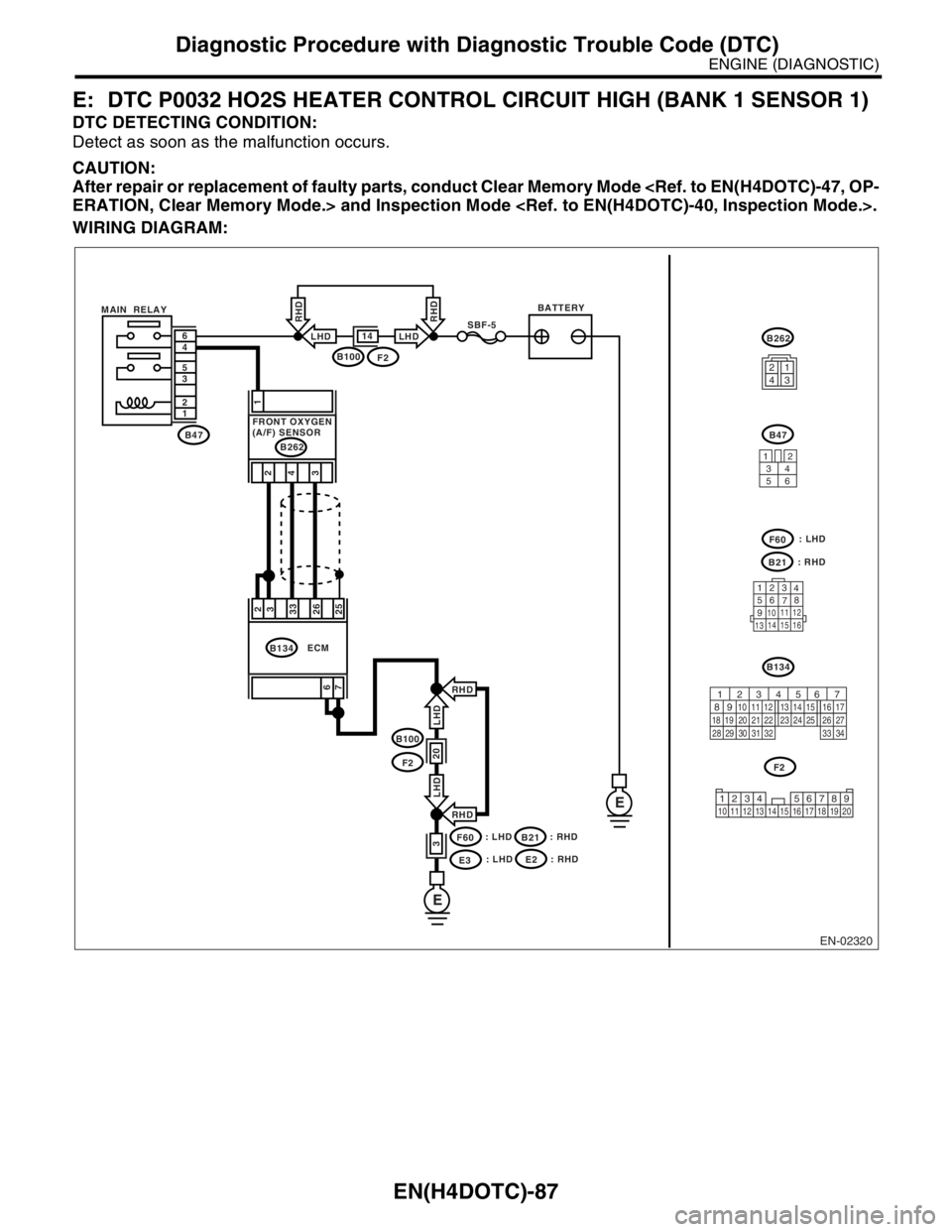
E: DTC P0032 HO2S HEATER CONTROL CIRCUIT HIGH (BANK 1 SENSOR 1)
DTC DETECTING CONDITION:
Detect as soon as the malfunction occurs.
CAUTION:
After repair or replacement of faulty parts, conduct Clear Memory Mode
WIRING DIAGRAM:
EN-02320
BATTERYMAIN RELAYSBF-5
B47 1 2 3 5 4 6
E
E
B100F2
14LHD
RHD
LHD
RHD
B100
F2
F60
E3
20
3
RHD
RHD6
72
3
33
26
25
ECMB134
: LHD: LHD
B21: RHD: RHD
1
4 2
3
B262
FRONT OXYGEN
(A/F) SENSOR
3412
56
123
4
56
78
9
1011 12
1314 15 16
B21
F60
B47
B262
B134
F2
LHD LHD
1234
56 7
82 1
94 310
24 22 23 25 11 12 13 14 15
26 27
2816 17
18 19 20 21
33 34 29
32 30 31
1234 5678910 11 12 13 14 15 16 17 18 19 20
: LHDE2: RHD