SUBARU FORESTER 2004 Service Repair Manual
Manufacturer: SUBARU, Model Year: 2004, Model line: FORESTER, Model: SUBARU FORESTER 2004Pages: 2870, PDF Size: 38.67 MB
Page 1811 of 2870

EN(H4DOTC)-178
ENGINE (DIAGNOSTIC)
Diagnostic Procedure with Diagnostic Trouble Code (DTC)
Step Check Yes No
1 CHECK HARNESS BETWEEN CAMSHAFT
POSITION SENSOR CONNECTOR AND ECM
CONNECTOR.
1) Turn the ignition switch to OFF.
2) Disconnect the connector from camshaft
position sensor connector.
3) Measure the resistance of harness
between camshaft position sensor connector
and engine ground.
Connector & terminal
(E15) No. 1 — Engine ground:Is the resistance more than
100 kΩ?Repair the har-
ness and connec-
tor.
N
OTE:
In this case repair
the following:
Open circuit in
harness between
camshaft position
sensor connector
and ECM connec-
tor
Poor contact in
ECM connector.
Poor contact in
coupling connectorGo to step 2.
2 CHECK HARNESS BETWEEN CAMSHAFT
POSITION SENSOR CONNECTOR AND ECM
CONNECTOR.
Measure the resistance of harness between
camshaft position sensor connector and
engine ground.
Connector & terminal
(E15) No. 1 — Engine ground:Is the resistance less than 10
Ω?Repair ground
short circuit in har-
ness between
camshaft position
sensor connector
and ECM connec-
tor.
N
OTE:
The harness be-
tween both con-
nectors are
shielded.Repair
ground short circuit
in harness togeth-
er with shield.Go to step 3.
3 CHECK HARNESS BETWEEN CAMSHAFT
POSITION SENSOR CONNECTOR AND ECM
CONNECTOR.
Measure the resistance of harness between
camshaft position sensor connector and
engine ground.
Connector & terminal
(E15) No. 2 — Engine ground:Is the resistance less than 5
Ω?Go to step 4.Repair the har-
ness and connec-
tor.
N
OTE:
In this case repair
the following:
Open circuit in
harness between
camshaft position
sensor connector
and ECM connec-
tor
Poor contact in
ECM connector
Poor contact in
coupling connector
4 CHECK CONDITION OF CAMSHAFT POSI-
TION SENSOR CONNECTOR.Is the camshaft position sensor
connector installation bolt tight-
ened securely?Go to step 5.Tighten the cam-
shaft position sen-
sor connector
installation bolt
securely.
5 CHECK CAMSHAFT POSITION SENSOR
CONNECTOR.
1) Remove the camshaft position sensor con-
nector.
2) Measure the resistance between connector
terminals of camshaft position sensor connector.
Te r m i n a l s
No. 1 — No. 2:Is the resistance 1 — 4 kΩ? Repair poor con-
tact in camshaft
position sensor
connector.Replace the cam-
shaft position sen-
sor connector.
Camshaft Position
Sensor.>
Page 1812 of 2870

EN(H4DOTC)-179
ENGINE (DIAGNOSTIC)
Diagnostic Procedure with Diagnostic Trouble Code (DTC)
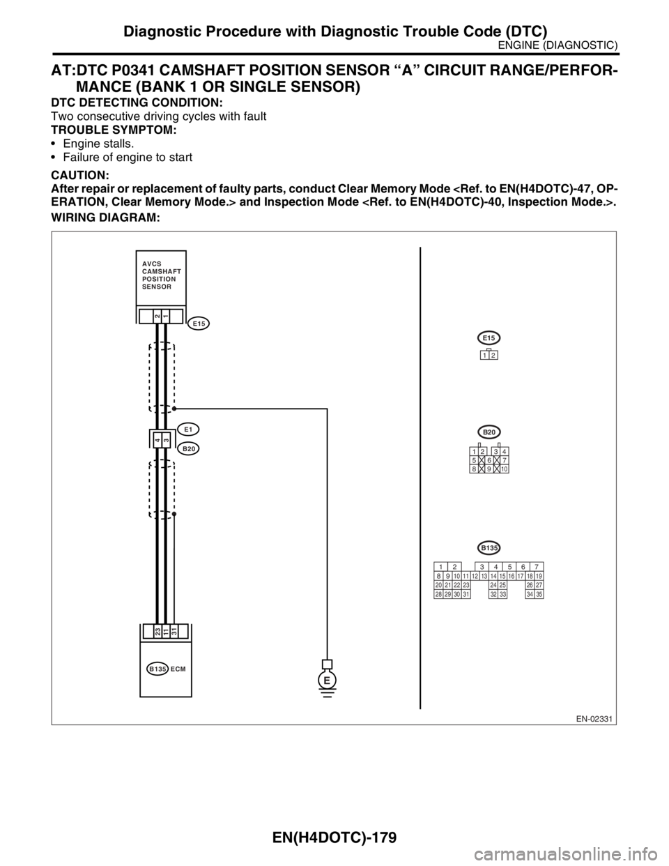
AT:DTC P0341 CAMSHAFT POSITION SENSOR “A” CIRCUIT RANGE/PERFOR-
MANCE (BANK 1 OR SINGLE SENSOR)
DTC DETECTING CONDITION:
Two consecutive driving cycles with fault
TROUBLE SYMPTOM:
Engine stalls.
Failure of engine to start
CAUTION:
After repair or replacement of faulty parts, conduct Clear Memory Mode
WIRING DIAGRAM:
EN-02331
4
3E1
E15
B20
2
1
B135 ECM
23
31 11
E
E15
12
12 34
56
7
89
10
B20
B135
567
82 1
94 310
24 22 23 2511 12 13 14 15
26 27
2816 17 18 19
20 21
29 30 31 32 33 34 35
AVCS
CAMSHAFT
POSITION
SENSOR
Page 1813 of 2870

EN(H4DOTC)-180
ENGINE (DIAGNOSTIC)
Diagnostic Procedure with Diagnostic Trouble Code (DTC)
Step Check Yes No
1 CHECK ANY OTHER DTC ON DISPLAY.Is any other DTC displayed? Inspect the rele-
vant DTC using
“List of Diagnostic
Trouble Code
(DTC)”.
List of Diagnostic
Trouble Code
(DTC).>Go to step 2.
2 CHECK HARNESS BETWEEN CAMSHAFT
POSITION SENSOR CONNECTOR AND ECM
CONNECTOR.
1) Turn the ignition switch to OFF.
2) Disconnect the connector from camshaft
position sensor connector.
3) Measure the resistance of harness
between camshaft position sensor connector
and engine ground.
Connector & terminal
(E15) No. 1 — Engine ground:Is the resistance more than
100 kΩ?Repair the har-
ness and connec-
tor.
N
OTE:
In this case repair
the following:
Open circuit in
harness between
camshaft position
sensor connector
and ECM connec-
tor
Poor contact in
ECM connector
Poor contact in
coupling connectorGo to step 3.
3 CHECK HARNESS BETWEEN CAMSHAFT
POSITION SENSOR CONNECTOR AND ECM
CONNECTOR.
Measure the resistance of harness between
camshaft position sensor connector and
engine ground.
Connector & terminal
(E15) No. 1 — Engine ground:Is the resistance less than 10
Ω?Repair ground
short circuit in har-
ness between
camshaft position
sensor connector
and ECM connec-
tor.
N
OTE:
The harness be-
tween both con-
nectors are
shielded.Repair
ground short circuit
in harness togeth-
er with shield.Go to step 4.
4 CHECK HARNESS BETWEEN CAMSHAFT
POSITION SENSOR CONNECTOR AND ECM
CONNECTOR.
Measure the resistance of harness between
camshaft position sensor connector and
engine ground.
Connector & terminal
(E15) No. 2 — Engine ground:Is the resistance less than 5
Ω?Go to step 5.Repair the har-
ness and connec-
tor.
NOTE:
In this case repair
the following:
Open circuit in
harness between
camshaft position
sensor connector
and ECM connec-
tor
Poor contact in
ECM connector
Poor contact in
coupling connector
Page 1814 of 2870

EN(H4DOTC)-181
ENGINE (DIAGNOSTIC)
Diagnostic Procedure with Diagnostic Trouble Code (DTC)
5 CHECK CONDITION OF CAMSHAFT POSI-
TION SENSOR CONNECTOR.Is the camshaft position sensor
connector installation bolt tight-
ened securely?Go to step 6.Tighten the cam-
shaft position sen-
sor connector
installation bolt
securely.
6 CHECK CAMSHAFT POSITION SENSOR
CONNECTOR.
1) Remove the camshaft position sensor con-
nector.
2) Measure the resistance between connector
terminals of camshaft position sensor connec-
tor.
Te r m i n a l s
No. 1 — No. 2:Is the resistance 1 — 4 kΩ? Go to step 7.Replace the cam-
shaft position sen-
sor connector.
Camshaft Position
Sensor.>
7 CHECK CONDITION OF CAMSHAFT POSI-
TION SENSOR CONNECTOR.
Turn the ignition switch to OFF.Is the camshaft position sensor
connector installation bolt tight-
ened securely?Go to step 8.Tighten the cam-
shaft position sen-
sor connector
installation bolt
securely.
8 CHECK CAM SPROCKET.
Remove the front belt cover.
cracked or damaged?Replace the cam
sprocket.
Cam Sprocket.>Go to step 9.
9 CHECK INSTALLATION CONDITION OF
TIMING BELT.
Turn the crankshaft, and align alignment mark
on camshaft sprocket with alignment mark on
timing belt cover LH.Is the timing belt dislocated
from its proper position?Repair installation
condition of timing
belt.
Timing Belt
Assembly.>Replace the cam-
shaft position sen-
sor connector.
Camshaft Position
Sensor.> Step Check Yes No
Page 1815 of 2870

EN(H4DOTC)-182
ENGINE (DIAGNOSTIC)
Diagnostic Procedure with Diagnostic Trouble Code (DTC)
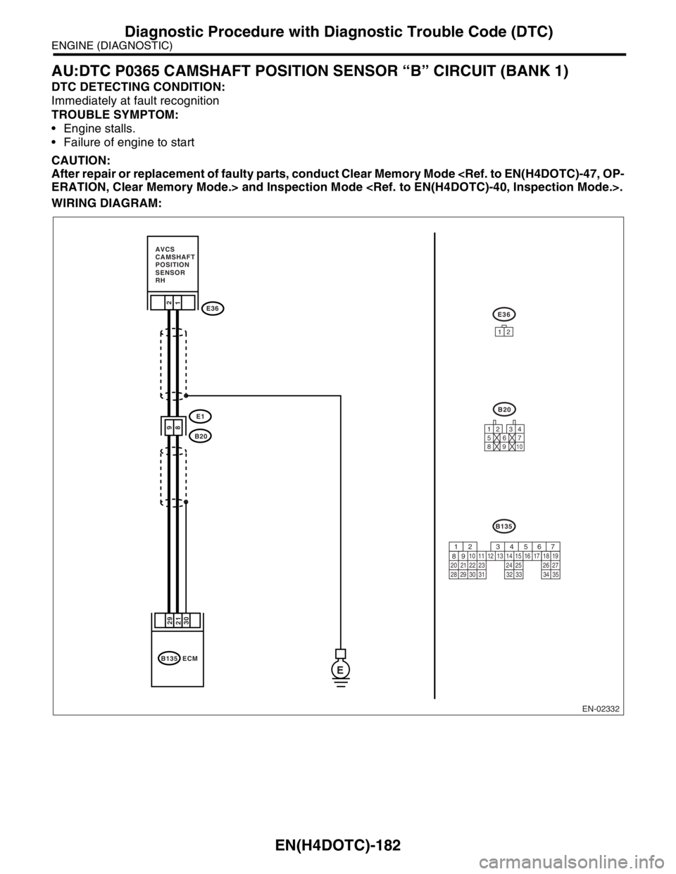
AU:DTC P0365 CAMSHAFT POSITION SENSOR “B” CIRCUIT (BANK 1)
DTC DETECTING CONDITION:
Immediately at fault recognition
TROUBLE SYMPTOM:
Engine stalls.
Failure of engine to start
CAUTION:
After repair or replacement of faulty parts, conduct Clear Memory Mode
WIRING DIAGRAM:
EN-02332
9
8E1
E36
B20
AVCS
CAMSHAFT
POSITION
SENSOR
RH
2
1
B135 ECM
29
30 21
E
E36
12
12 34
56
7
89
10
B20
B135
567
82 1
94 310
24 22 23 2511 12 13 14 15
26 27
2816 17 18 19
20 21
29 30 31 32 33 34 35
Page 1816 of 2870

EN(H4DOTC)-183
ENGINE (DIAGNOSTIC)
Diagnostic Procedure with Diagnostic Trouble Code (DTC)
Step Check Yes No
1 CHECK CURRENT DATA.
1) Start the engine.
2) Drive the vehicle at the speed of approx. 30
km/h (19 MPH), and then measure the ignition
timing advance angle using Subaru Select
Monitor or OBD-II general scan tool.
N
OTE:
Subaru Select Monitor
For detailed operation procedure, refer to
“READ CURRENT DATA SHOWN ON DIS-
PLAY FOR ENGINE”.
OBD-II general scan tool
For detailed operation procedures, refer to the
OBD-II General Scan Tool Operation Manual.Does the ignition timing
advance angle changed
smoothly according to engine
output?
Idling: −2 — +2°
Driving: −2 — +50°Repair the poor
contact connector.
N
OTE:
In this case, repair
the following:
Poor contact of
AVCS camshaft
position sensor
connector.
Poor contact in
ECM connector.Go to step 2.
2 CHECK HARNESS BETWEEN AVCS CAM-
SHAFT POSITION SENSOR CONNECTOR
AND ECM CONNECTOR.
1) Turn the ignition switch to OFF.
2) Disconnect the connector from AVCS cam-
shaft position sensor connector and ECM.
3) Measure the resistance of harness
between AVCS camshaft position sensor con-
nector and engine ground.
Connector & terminal
(B36) No. 1 — (B135) No. 21:
(B36) No. 2 — (B135) No. 29:Is the resistance less than 1
Ω?Go to step 3.Repair the har-
ness and connec-
tor.
N
OTE:
In this case, repair
the following:
Open circuit in
harness between
AVCS camshaft
position sensor
connector and
ECM connector
Poor contact in
ECM connector
Poor contact in
coupling connector
3 CHECK HARNESS BETWEEN AVCS CAM-
SHAFT POSITION SENSOR CONNECTOR
AND ECM CONNECTOR.
Measure the resistance of harness between
AVCS camshaft position sensor connector and
engine ground.
Connector & terminal
(E36) No. 1 — Engine ground:
(E36) No. 2 — Engine ground:Is the resistance more than 1
MΩ?Go to step 4.Repair the ground
short circuit in har-
ness between
AVCS camshaft
position sensor
connector and
ECM connector.
NOTE:
The harness be-
tween both con-
nectors are
shielded.Repair
ground short circuit
in harness togeth-
er with shield.
4 CHECK CONDITION OF AVCS CAMSHAFT
POSITION SENSOR CONNECTOR.Is the AVCS camshaft position
sensor connector installation
bolt tightened securely?Go to step 5.Tighten the AVCS
camshaft position
sensor connector
installation bolt
securely.
5 CHECK AVCS CAMSHAFT POSITION SEN-
SOR CONNECTOR.
1) Remove the AVCS camshaft position sen-
sor.
2) Measure the resistance between the AVCS
camshaft position sensor connector terminals.
Te r m i n a l s
No. 1 — No. 2:Is the resistance 1 — 4 kΩ? Check for the clog-
ging on oil pres-
sure routing of oil
flow control sole-
noid valve.Replace the AVCS
camshaft position
sensor connector.
AVCS Camshaft
Position Sensor.>
Page 1817 of 2870

EN(H4DOTC)-184
ENGINE (DIAGNOSTIC)
Diagnostic Procedure with Diagnostic Trouble Code (DTC)
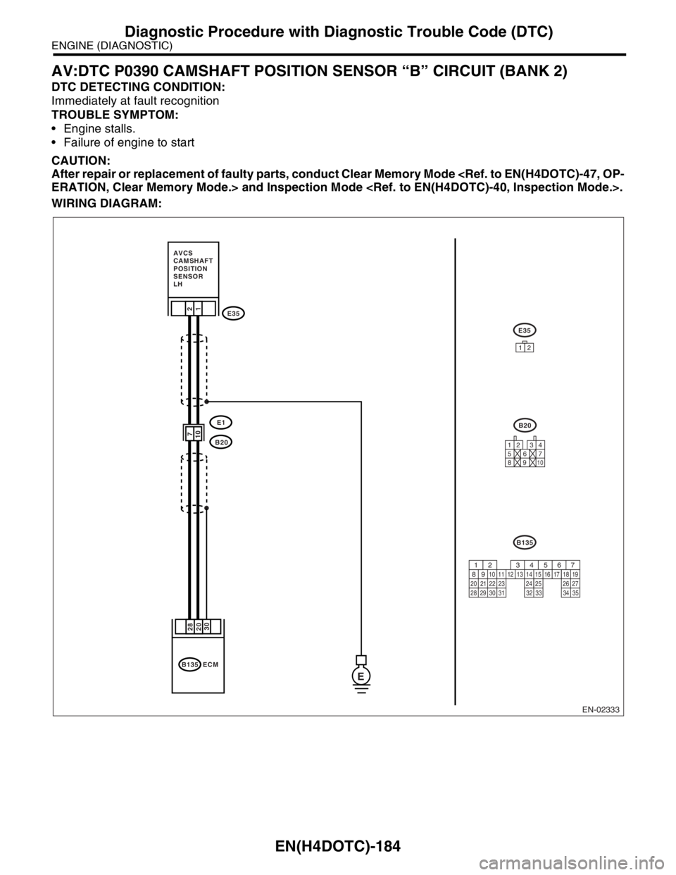
AV:DTC P0390 CAMSHAFT POSITION SENSOR “B” CIRCUIT (BANK 2)
DTC DETECTING CONDITION:
Immediately at fault recognition
TROUBLE SYMPTOM:
Engine stalls.
Failure of engine to start
CAUTION:
After repair or replacement of faulty parts, conduct Clear Memory Mode
WIRING DIAGRAM:
EN-02333
E1
E35
B20
2
1
B135
ECM
28
30 20
E
E35
12
12 34
56
7
89
10
B20
B135
AVCS
CAMSHAFT
POSITION
SENSOR
LH
567
82 1
94 310
24 22 23 2511 12 13 14 15
26 27
2816 17 18 19
20 21
29 30 31 32 33 34 35
7
10
Page 1818 of 2870

EN(H4DOTC)-185
ENGINE (DIAGNOSTIC)
Diagnostic Procedure with Diagnostic Trouble Code (DTC)
Step Check Yes No
1 CHECK CURRENT DATA.
1) Start the engine.
2) Drive the vehicle at the speed of approx. 30
km/h (19 MPH), and then measure the ignition
timing advance angle using Subaru Select
Monitor or OBD-II general scan tool.
N
OTE:
Subaru Select Monitor
For detailed operation procedure, refer to
“READ CURRENT DATA SHOWN ON DIS-
PLAY FOR ENGINE”.
OBD-II general scan tool
For detailed operation procedures, refer to the
OBD-II General Scan Tool Operation Manual.Does the ignition timing
advance angle changed
smoothly according to engine
output?
Idling: −2 — +2°
Driving: −2 — +50°Repair the poor
contact connector.
N
OTE:
In this case, repair
the following:
Poor contact of
AVCS camshaft
position sensor
connector.
Poor contact in
ECM connector.Go to step 2.
2 CHECK HARNESS BETWEEN AVCS CAM-
SHAFT POSITION SENSOR CONNECTOR
AND ECM CONNECTOR.
1) Turn the ignition switch to OFF.
2) Disconnect the connector from AVCS cam-
shaft position sensor connector and ECM.
3) Measure the resistance of harness
between AVCS camshaft position sensor con-
nector and engine ground.
Connector & terminal
(B35) No. 1 — (B135) No. 20:
(B35) No. 2 — (B135) No. 28:Is the resistance less than 1
Ω?Go to step 3.Repair the har-
ness and connec-
tor.
N
OTE:
In this case, repair
the following:
Open circuit in
harness between
AVCS camshaft
position sensor
connector and
ECM connector
Poor contact in
ECM connector.
Poor contact in
coupling connector
3 CHECK HARNESS BETWEEN AVCS CAM-
SHAFT POSITION SENSOR CONNECTOR
AND ECM CONNECTOR.
Measure the resistance of harness between
AVCS camshaft position sensor connector and
engine ground.
Connector & terminal
(E35) No. 1 — Engine ground:
(E35) No. 2 — Engine ground:Is the resistance more than 1
MΩ?Go to step 4.Repair the ground
short circuit in har-
ness between
AVCS camshaft
position sensor
connector and
ECM connector.
NOTE:
The harness be-
tween both con-
nectors are
shielded.Repair
ground short circuit
in harness togeth-
er with shield.
4 CHECK CONDITION OF AVCS CAMSHAFT
POSITION SENSOR CONNECTOR.Is the AVCS camshaft position
sensor connector installation
bolt tightened securely?Go to step 5.Tighten the AVCS
camshaft position
sensor connector
installation bolt
securely.
5 CHECK AVCS CAMSHAFT POSITION SEN-
SOR CONNECTOR.
1) Remove the AVCS camshaft position sen-
sor connector.
2) Measure the resistance between the AVCS
camshaft position sensor connector terminals.
Te r m i n a l s
No. 1 — No. 2:Is the resistance 1 — 4 kΩ? Check for the oil
clogging on oil
pressure routing of
oil flow control
solenoid valve.Replace the AVCS
camshaft position
sensor connector.
AVCS Camshaft
Position Sensor.>
Page 1819 of 2870

EN(H4DOTC)-186
ENGINE (DIAGNOSTIC)
Diagnostic Procedure with Diagnostic Trouble Code (DTC)
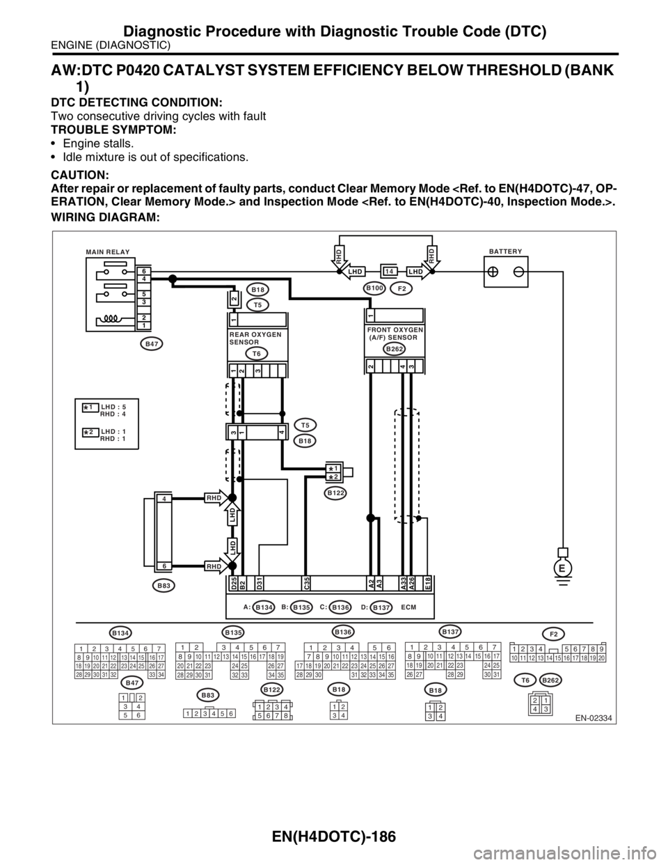
AW:DTC P0420 CATALYST SYSTEM EFFICIENCY BELOW THRESHOLD (BANK
1)
DTC DETECTING CONDITION:
Two consecutive driving cycles with fault
TROUBLE SYMPTOM:
Engine stalls.
Idle mixture is out of specifications.
CAUTION:
After repair or replacement of faulty parts, conduct Clear Memory Mode
WIRING DIAGRAM:
EN-02334
BATTERY
MAIN RELAY
E
6
4
5
3
2
1
2
4
31
FRONT OXYGEN
(A/F) SENSOR
D25
B2
D31
C35
A2
A3
A33
A26
E18
REAR OXYGEN
SENSOR
T6
B47
B47
34
12
56
B134B137
B83
1
23456
B18
B262
34
12
B134A:
B135B:
B136ECM C:
B135
B83 LHD : 5
RHD : 4
LHD : 1
RHD : 1
*1
*2F2 B100
567
82 1
94 310
22 23 11 12 13 14 15
24 25
2616 17
18 19 20 21
27 28 29 30 31
F2
1234 5678910 11 12 13 14 15 16 17 18 19 20567
82 1
94 310
24 22 23 2511 12 13 14 15
26 27
2816 17 18 19
20 21
29 30 31 32 33 34 3556 7
82 1
94 310
24 22 23 25 11 12 13 14 15
26 27
2816 17
18 19 20 21
33 34 29
32 30 31
B136
56
782 1
94 310
24 22 23 2511 12 13
1415
26 27
2816
17 18 19 20 21
33 34 29
32 30
31 35
B122
12345678
B262T6B1812341234
1
2
31
B18
T5
3
1
4
4
6
B137
D:
14RHD
RHDLHD LHD
2
B122*2*1
B18
T5
RHD
LHD
RHD
LHD
Page 1820 of 2870

EN(H4DOTC)-187
ENGINE (DIAGNOSTIC)
Diagnostic Procedure with Diagnostic Trouble Code (DTC)
Step Check Yes No
1 CHECK ANY OTHER DTC ON DISPLAY.Is any other DTC displayed? Inspect the rele-
vant DTC using
“List of Diagnostic
Trouble Code
(DTC)”.
List of Diagnostic
Trouble Code
(DTC).>
N
OTE:
In this case, it is
not necessary to
inspect DTC
P0420.Go to step 2.
2 CHECK EXHAUST SYSTEM.
Check for gas leaks or air suction caused by
loose or dislocated nuts and bolts, and open
hole at exhaust pipes.
N
OTE:
Check the following positions.
Between cylinder head and front exhaust
pipe
Between front exhaust pipe and front cata-
lytic converter
Between front catalytic converter and rear
catalytic converterIs there a fault in exhaust sys-
tem?Repair or replace
the exhaust sys-
tem.
General Descrip-
tion.>Go to step 3.
3 CHECK REAR CATALYTIC CONVERTER.
Separate rear catalytic converter from rear
exhaust pipe.Is there damage at rear face of
rear catalyst?Replace the front
and rear catalytic
converter
Front Catalytic
Converter.>
Rear Catalytic
Converter.>Go to step 4.
4 CHECK FRONT CATALYTIC CONVERTER.
Remove the front catalytic converter.Is there damage at rear face or
front face of front catalyst?Replace the front
catalytic con-
verter.
Front Catalytic
Converter.>Contact the SUB-
ARU dealer.
NOTE:
Inspection by DTM
is required, be-
cause probable
cause is deteriora-
tion of multiple
parts.